VRやゲーム制作において、アニメーションは非常に重要です。
Unityには様々なアニメーション機能が用意されています。
Unityに用意されたアニメーション機能を使うと、プログラミング不要で高度なアニメーションを作ることができます。
本記事では図形モデルを動かすアニメーションについて、基本から紹介します。
アニメーションビューを表示する
最初にUnityの準備をします。
新しいプロジェクトを立ち上げ、新しいシーンを制作しましょう。
Unityでアニメーションを作成する際は、「アニメーションウィンドウ」上で作業をします。
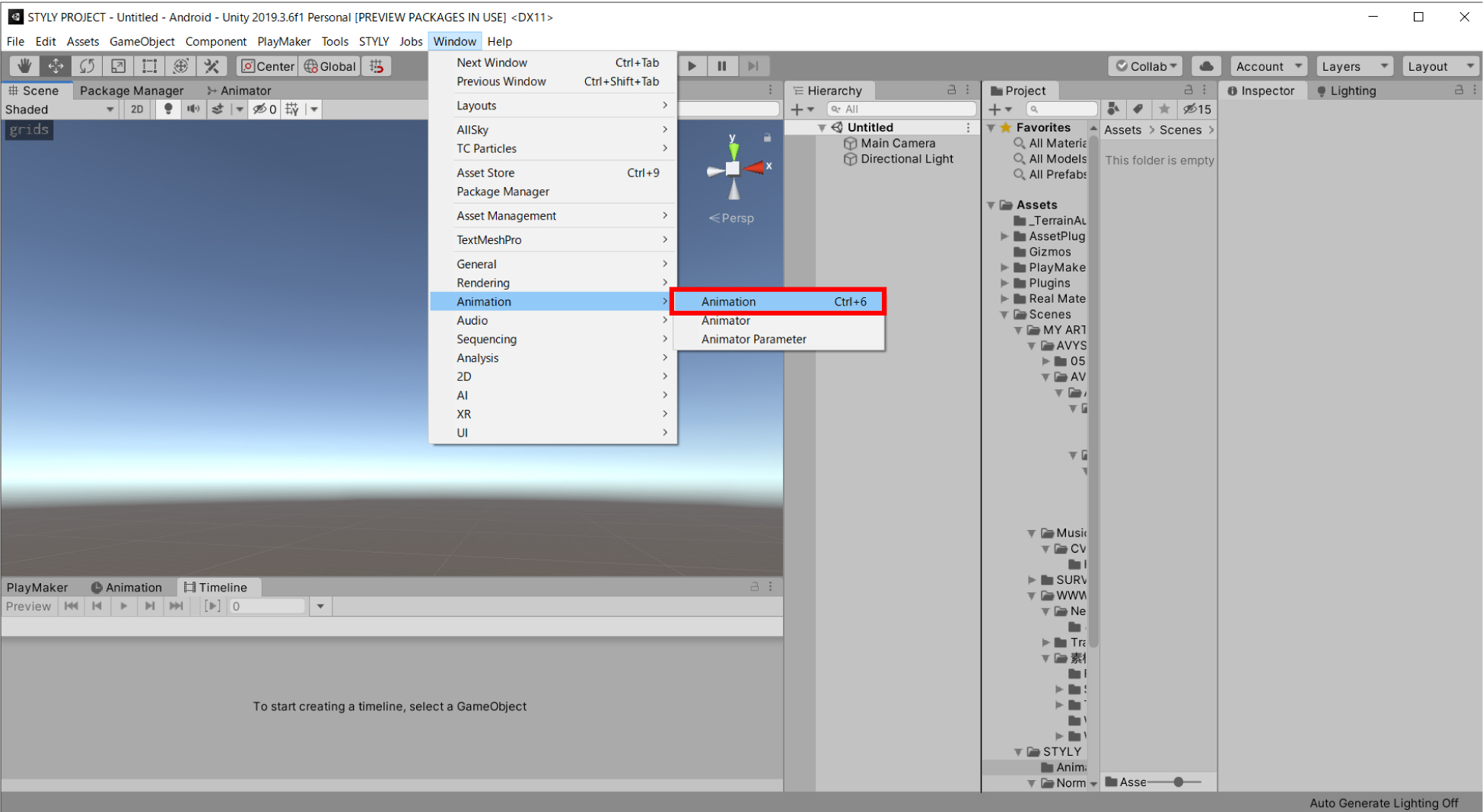
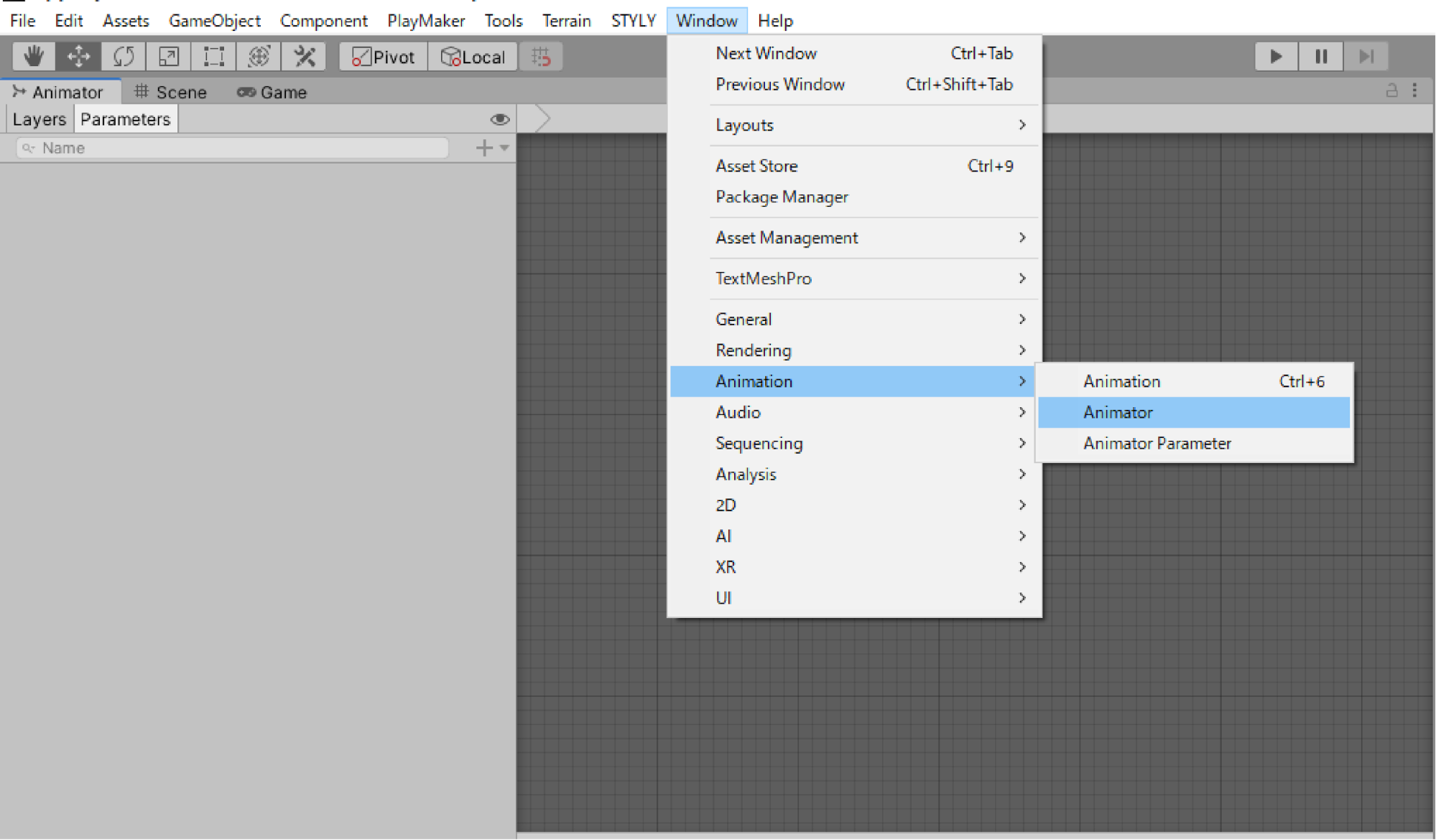
アニメーションウィンドウを表示するにはまず、「Window」メニューから「Animation」を選択してください。
アニメーションウィンドウが別ウィンドウで表示されました。
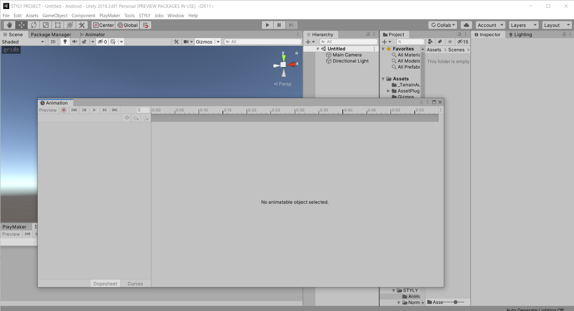
このままでは作業がしづらいので、同じウィンドウにまとめます。
「Animation」と書かれたタブの部分をドラッグしてどこかのウィンドウに組み込みます。本講座は下のウィンドウにまとめました。
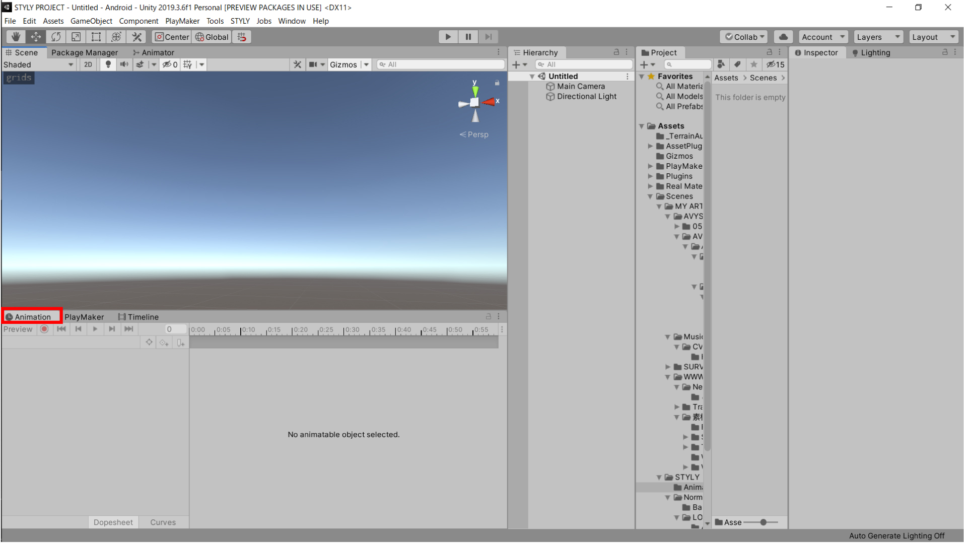
これでアニメーションウィンドウの準備ができました。
実際に3Dモデルにアニメーションをつけましょう。
Sphereを移動させる
3Dモデルを使って、実際にアニメーションを作成しましょう。
今回は「Sphere」を使います。
ヒエラルキーウィンドウ(以下、ヒエラルキーと呼ぶ)で右クリックをして、3D Object > Sphere をクリックしてください。
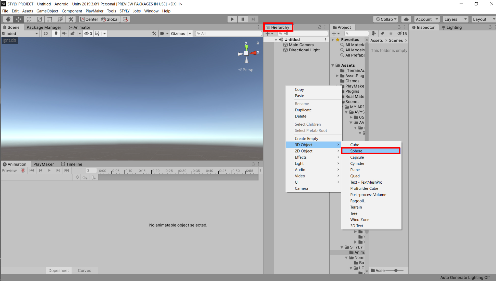
シーンビュー上にSphereが表示されます。
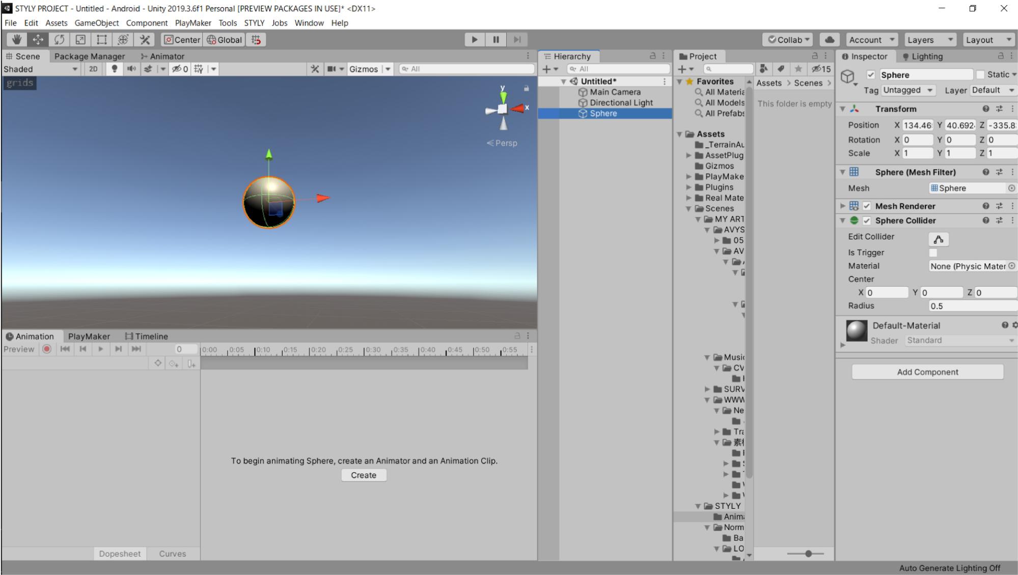
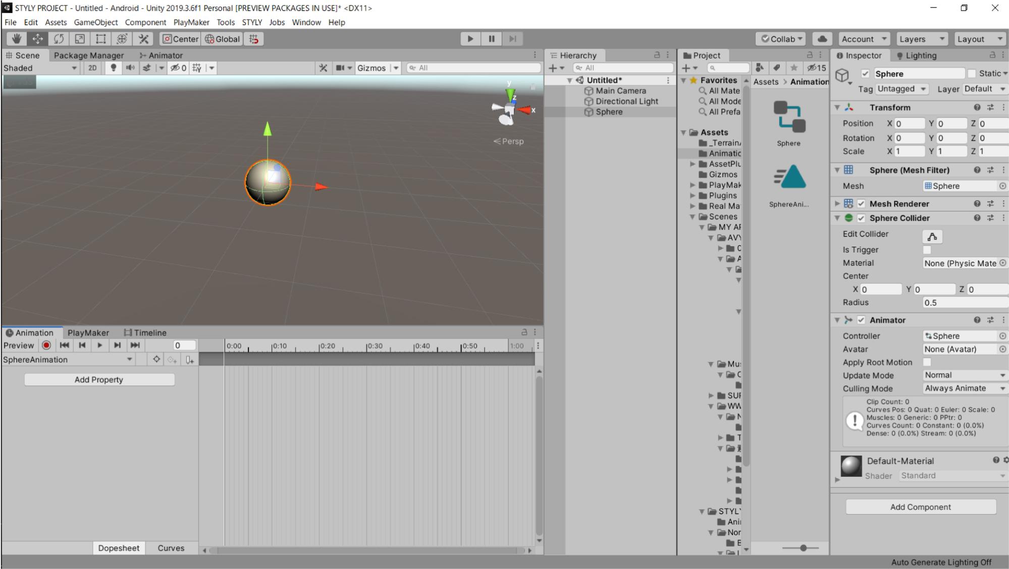
Sphereの位置を調整しましょう。
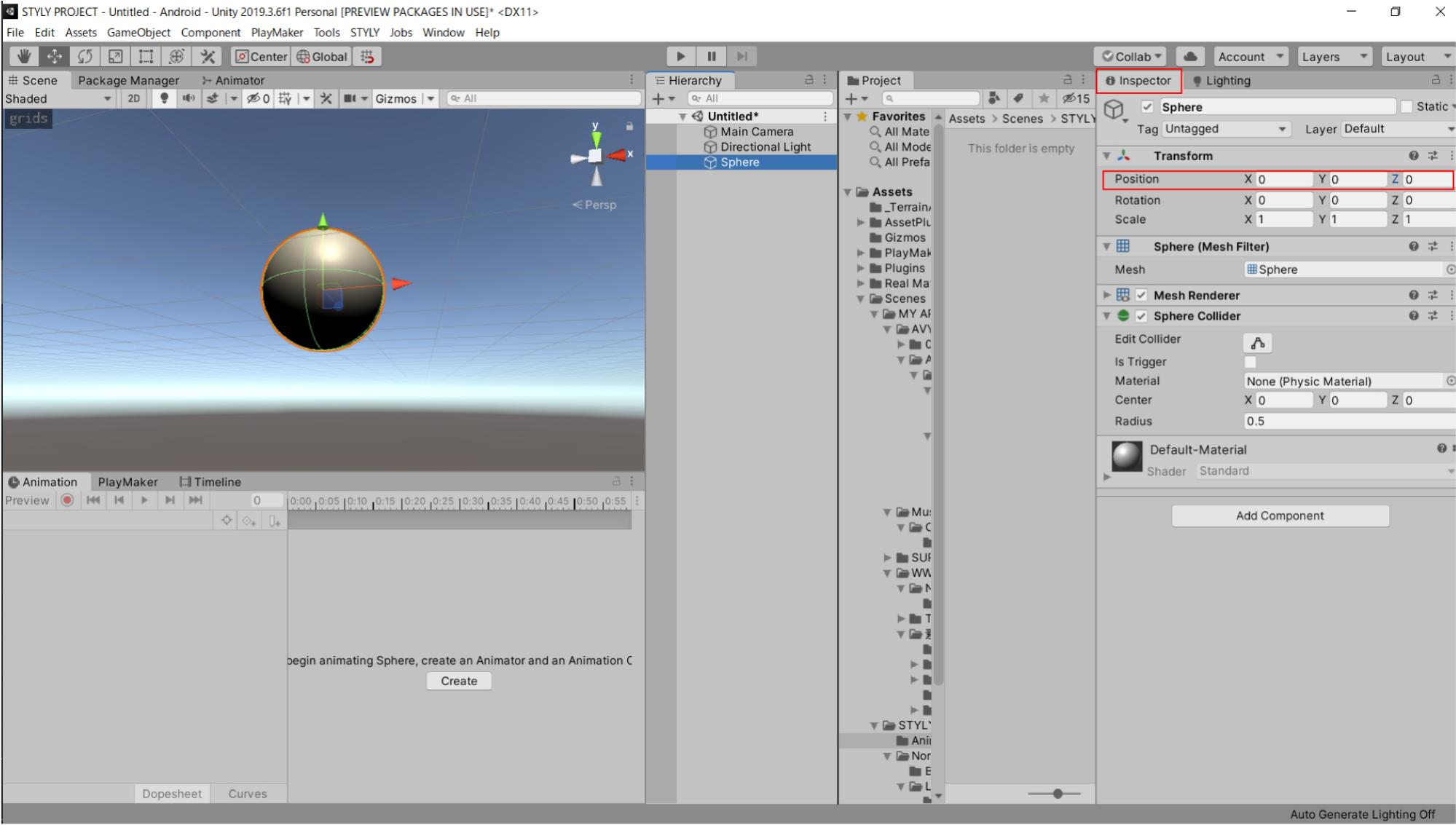
Sphereを選択した状態で、インスペクターウィンドウ(以下、インスペクターと呼ぶ)のTransformを設定してください。
TransformのPositionの X,Y,Z を全て(0,0,0)に設定します。
以下と同じPositionの数値に設定したら、準備完了です。
このSphereにアニメーションを作成しましょう。
Sphereを選択した状態で、アニメーションウィンドウのCreateボタンを選択します。
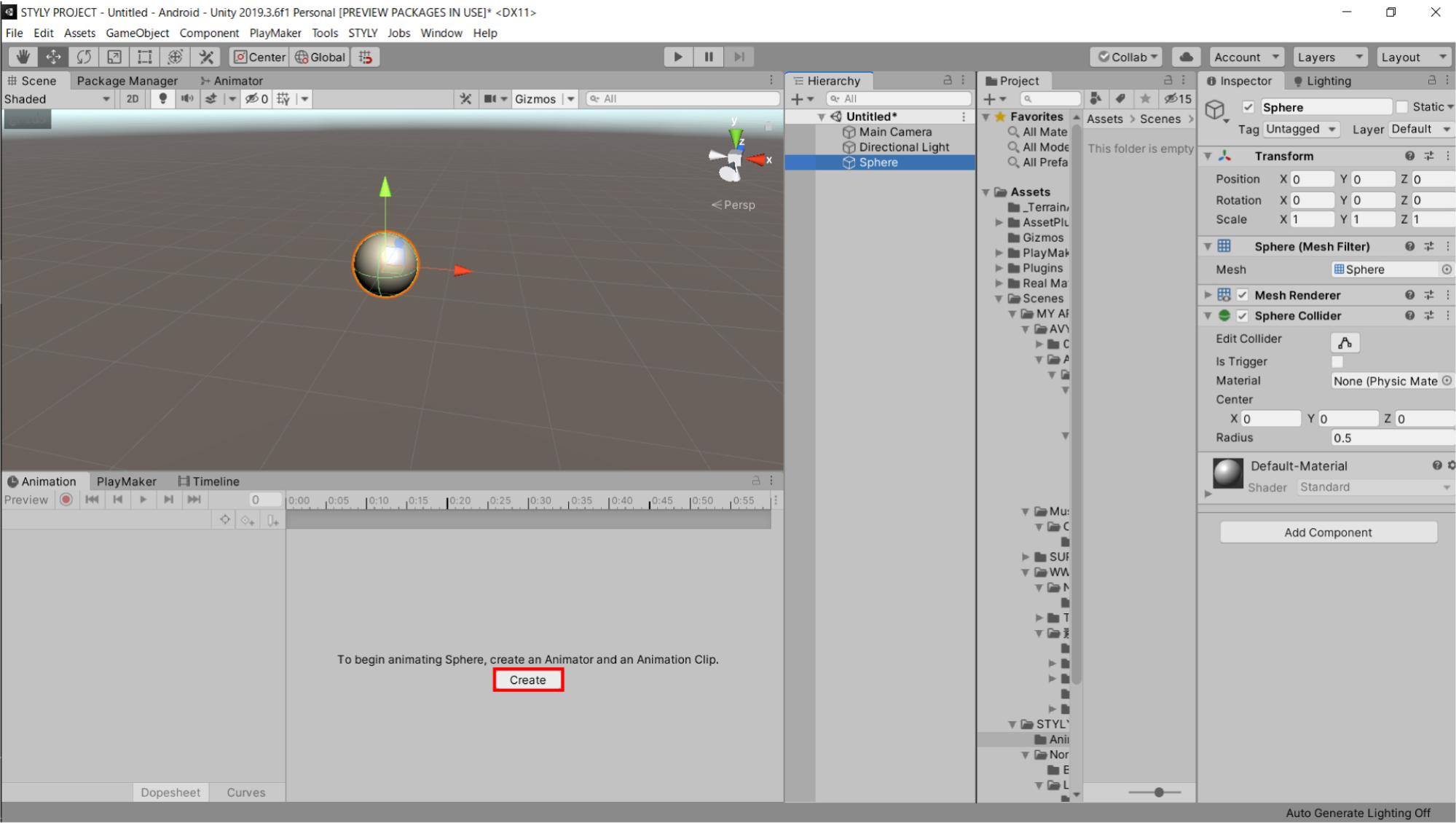
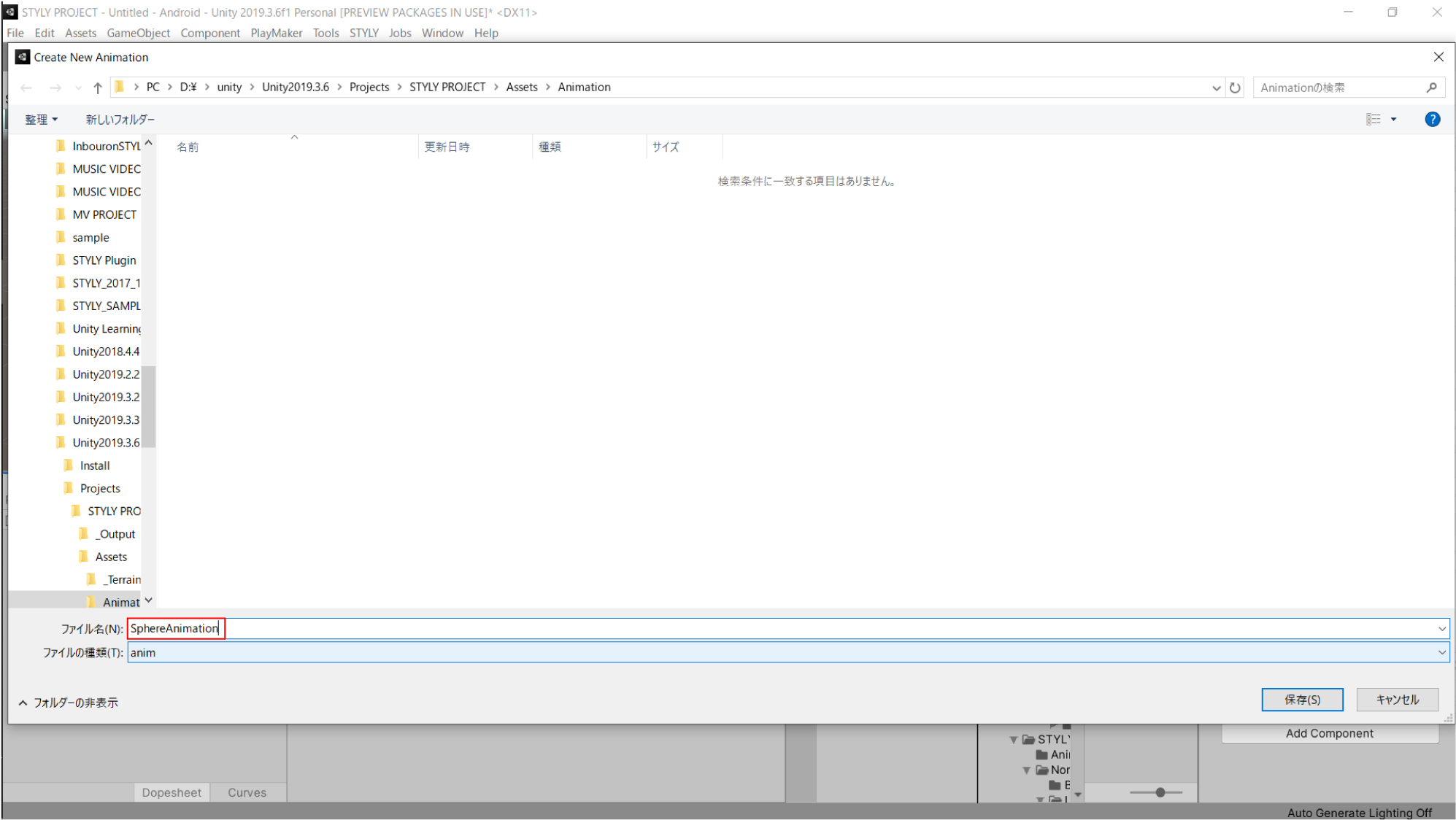
すると、ファイル保存ダイアログが表示されます。
プロジェクト内の任意の場所に保存しましょう。
今回は「Assets」フォルダ内に「Animation」というフォルダを作り、その中に保存します。
ファイル名は「SphereAnimation」とします。
プロジェクト内の保存した場所を見てみましょう。
すると、画像のように2つのオブジェクトが追加されています。
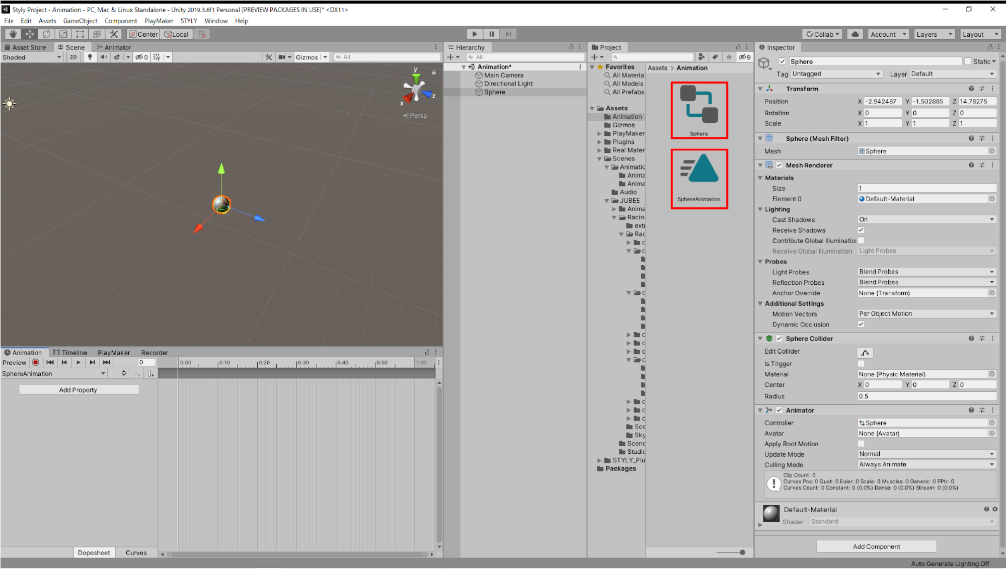
SphereAnimationと書かれた三角形のオブジェクトは「Animation Clip」です。
アニメーションウィンドウで作成するアニメーションの情報は、この中に格納されます。
Cubeと書かれた四角形が2つと、2本の線のオブジェクトは「Animator Controller」となります。
Animation ControllerはAnimation Clipを実行する機能があります。
詳しくは「Animator Controllerを理解する」で説明します。
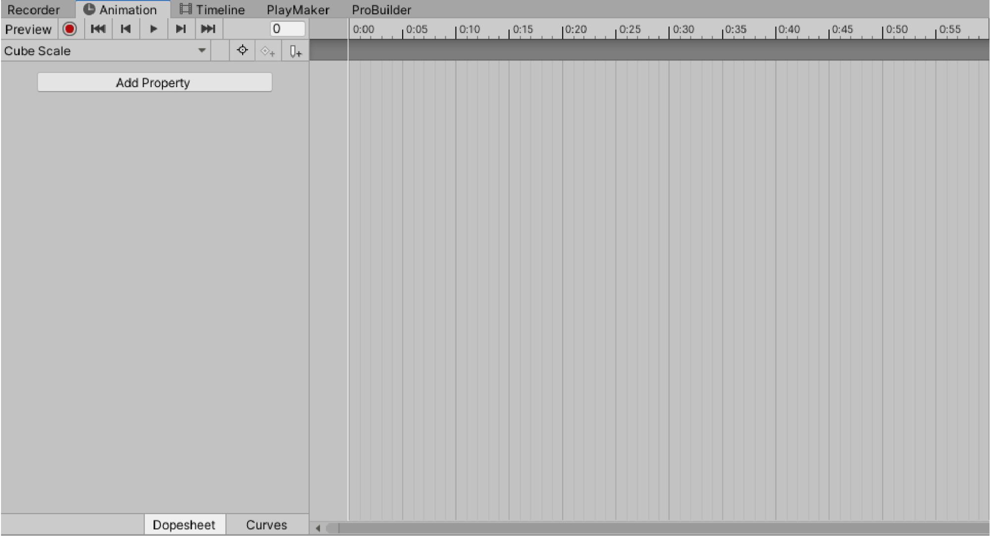
アニメーションウィンドウには横軸のグラフが表示されます。
このグラフ上でSphereが移動するアニメーションを作ります。
アニメーションウィンドウのAdd Propertyを選択します。
Add Property > Transform > Position(の右端の「+」)からPositionをプロパティとして追加します。
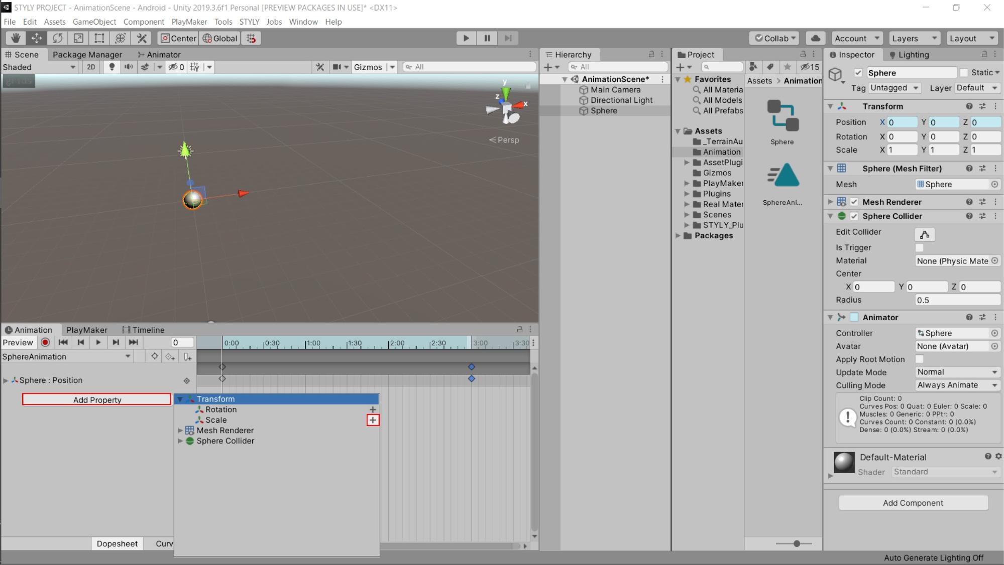
ボタンを押すと以下のようにProperty欄に「Position」の項目が表示されます。
Transformから選択できるプロパティは以下の機能を持ちます。
Position
オブジェクトの位置を設定できます。
変化させることで、移動させるアニメーションが作れます。
Rotation
オブジェクトの回転を設定できます。
変化させることで、回転するアニメーションを作れます。
Scale
オブジェクトの大きさを設定できます。
変化させることで、伸縮するアニメーションを作れます。
グラフの見方ですが、横軸は時間、アニメーションするときのタイムラインを表しています。
数値は初期表示では秒数で表示されていて、1:00が1秒になります。
0:01(1目盛り)は1秒を60分割したものになっており、この1目盛りの時間を「フレーム」と呼びます。
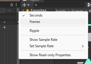
また右上の3点のメニューを開くと、グラフの表示方法を変えられます。
現在は秒数で刻まれていますが、フレーム数での表示も可能です。
この状態でのアニメーションウィンドウの各要素を説明します。
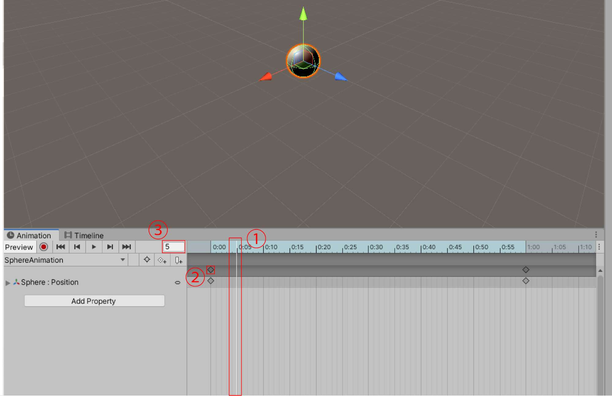
①再生ヘッド
グラフ上の白の縦線、再生ヘッドの位置が現在のアニメーションの状態になります。
再生ヘッドの位置の状態がシーン上に表示されます。
②キー(キーフレーム)
アニメーションの情報を設定している印です。
◇のマークで表示されます。
③フレーム数値
再生ヘッドの位置のフレームの値を表示しています。
1秒は60フレーム、2秒は120フレーム、3秒は180フレーム、1分は3600フレームとなります。
細かい設定をする場合は、数値も確認しましょう。
フレームを設定してアニメーションを設定します。
グラフ上の「0:00」のキー(◇のマーク)はそのままにしておきます。
キーを選択した状態で右クリックをし、「Delete Key」から削除できます。
次に、グラフを拡大します。
グラフ上でマウスのスクロールホイールを動かして、拡大させましょう。
だいたい5:00が見えるぐらいまで拡大します。
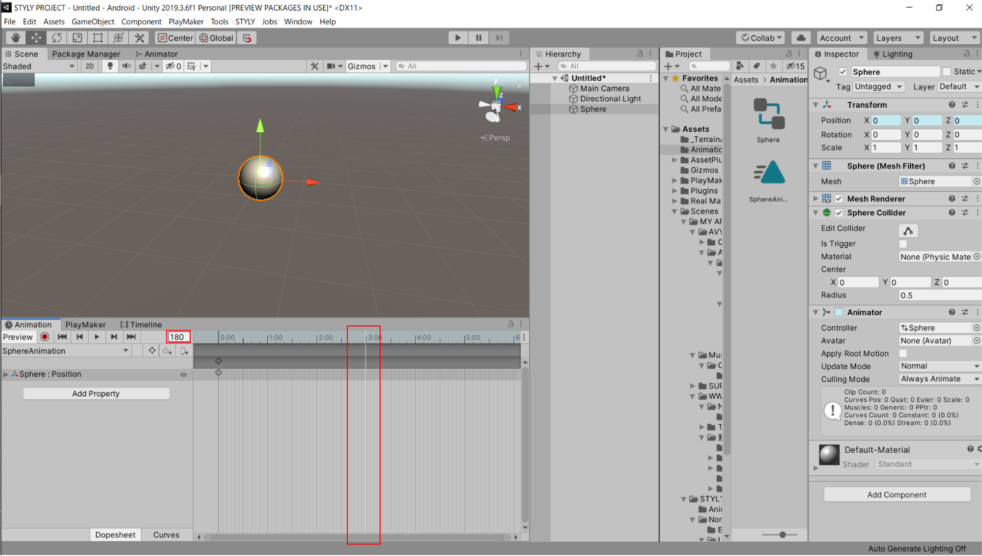
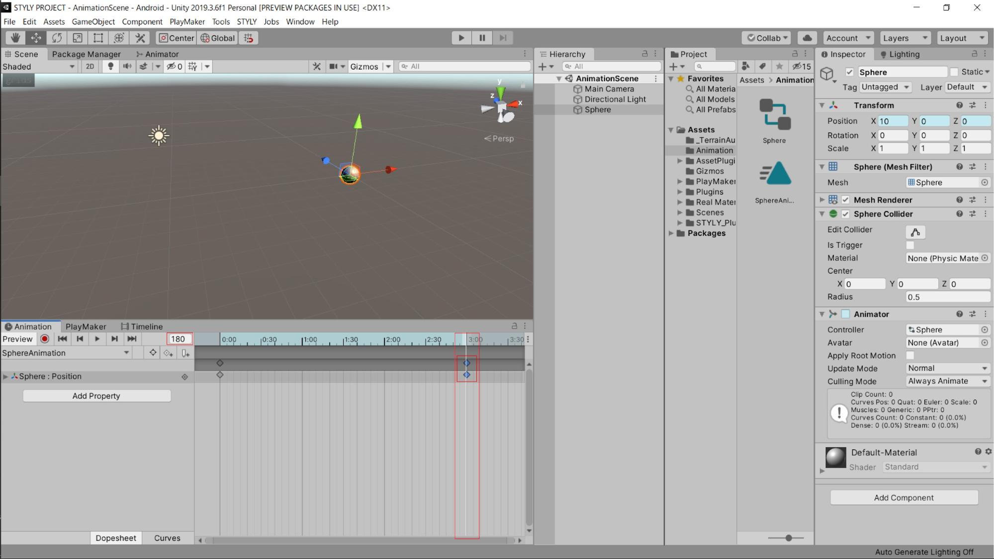
次に、フレームを「3:00」の場所に合わせます。
拡大して細かい部分まで見えない場合は、左の数値を「180」に合わせましょう。
これで3:00の位置に設定できました。
このフレームに合わせた状態で、インスペクターのTransformの数値を変えます。
TransformのPositionのXの数字を0から10にしましょう。
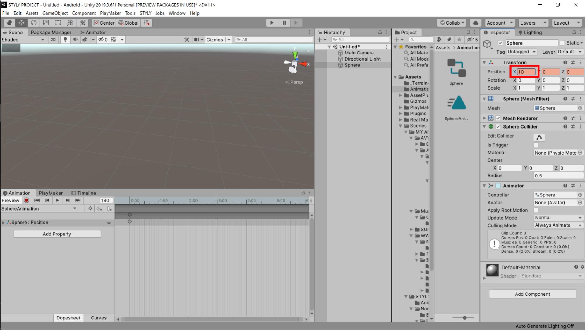
10に設定して、アニメーションウィンドウの「Add Keyframe」ボタンを押します。
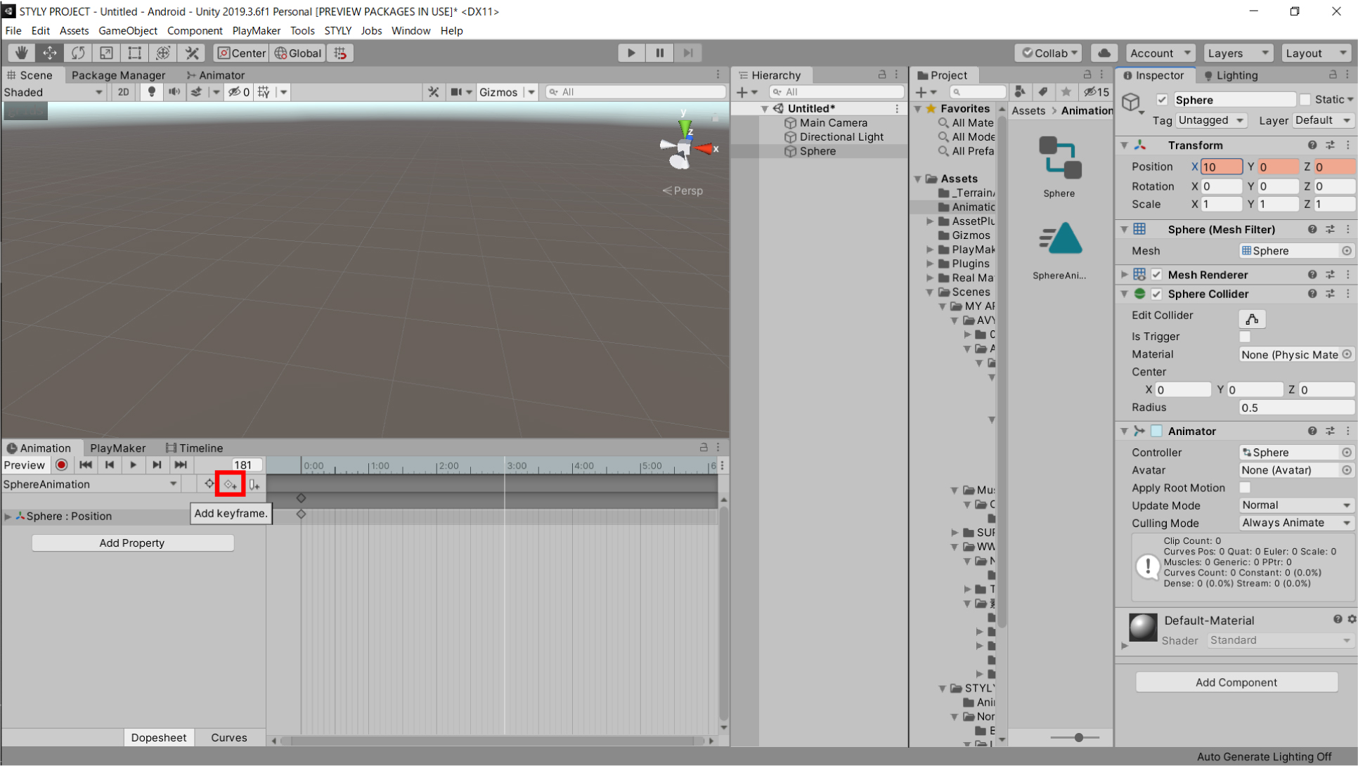
グラフ上にキーが打たれました。
これでアニメーションの設定が完了です。
アニメーションの確認をしてみましょう。
アニメーションウィンドウの再生ボタン(▶マーク)を押してください。
すると、以下のようにシーンビュー上でSphereが移動します。
アニメーションの基本的な設定はこれで完了です。
アニメーションを修正する
キーフレームの修正方法を説明します。
3秒で、X座標が0から10の位置に移動するアニメーションを作成しましたが、これを3秒で0から20に移動するアニメーションに修正しましょう。
最初に、3:00の位置に再生ヘッドを設定します。
この位置が1フレームでもずれていると修正できないため、数値が180になっていることも確認しましょう。
3:00の位置に設定したら、先ほど設定したキーを選択しましょう(選択したら灰色から青色に変化します)。
キーを選択した状態で、右のインスペクターのTransformのPositionのXの値を10から20に変えましょう。

Positionの画面が薄赤色に変わったままにし、通常のアニメーションの設定と同じように、アニメーションウィンドウの「Add Keyframe」を押しましょう。
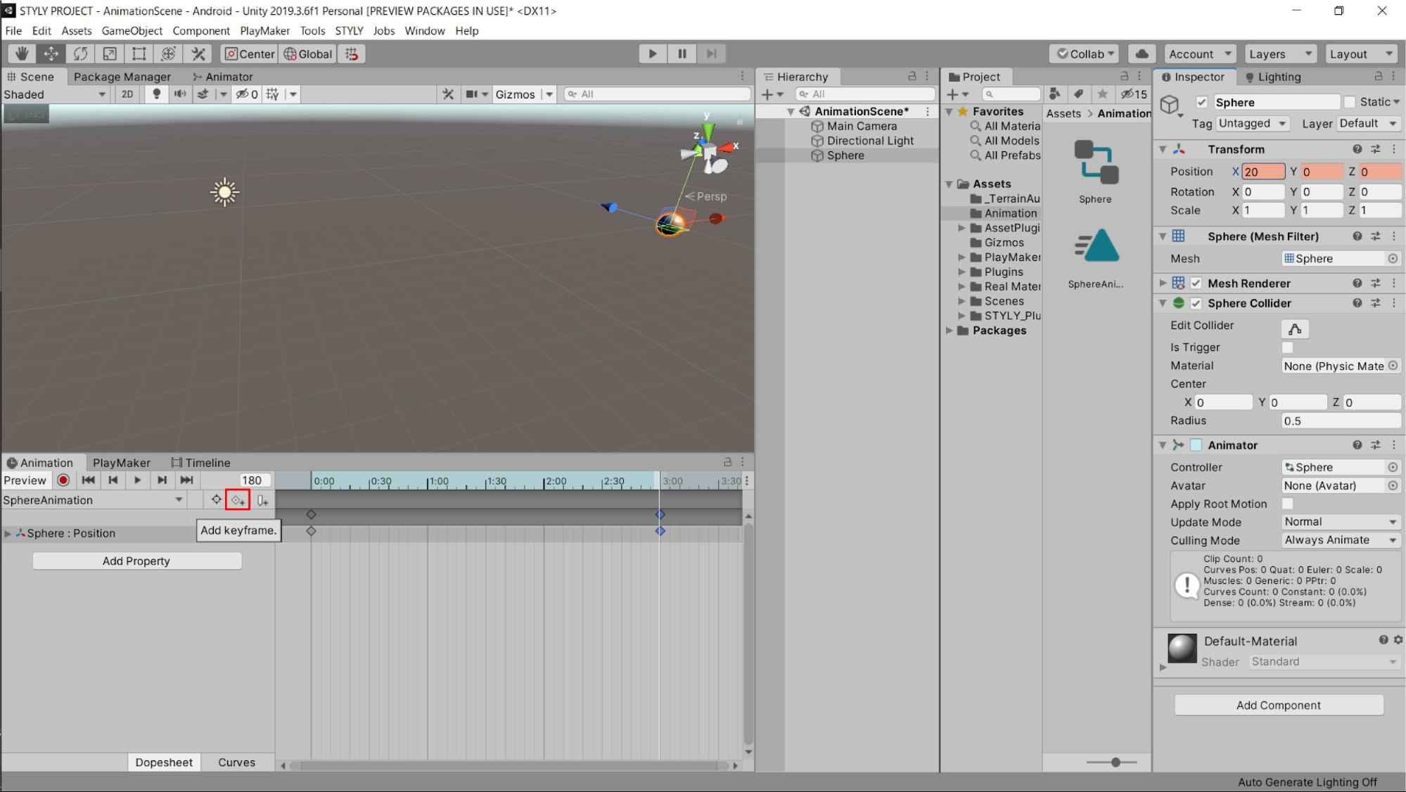
キーを打ち込むと、先ほど作成したキーは上書きされて、修正が完了しました。
実際に確認しましょう。
移動距離が2倍になりました。
これでアニメーションを後から修正する方法は以上になります。
同じ手順で、Sphereの大きさを変えるアニメーションを設定しましょう。
アニメーションウィンドウのAdd Propertyを選択し、TransformのScaleを選択しましょう。
アニメーションウィンドウにScaleの項目が追加されました。
グラフを3:00の位置に設定しましょう(数値は180です)。
その位置に、予めScaleのキーが設定されています。
3:00の位置のキーを選択しましょう。
※この際に、Positionのキーは選択しないようにしましょう。
以下のようにしてください。
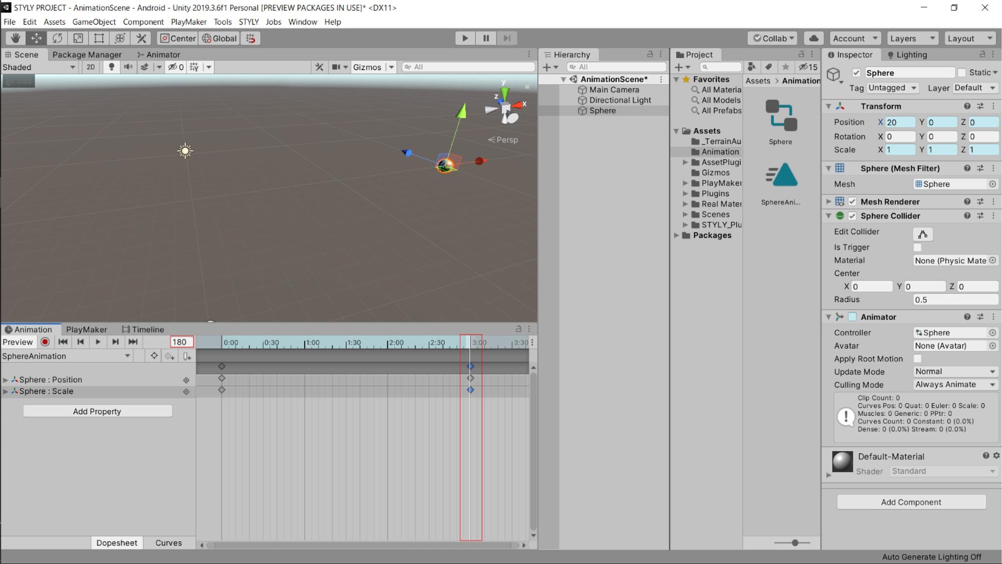
この状態で、TransformのScaleの値を変えます。
Scaleの X,Y,Zが1,1,1になっていますが、この値を3,3,3に変えましょう。
値を変えたら、Add Keyframeを選択します。
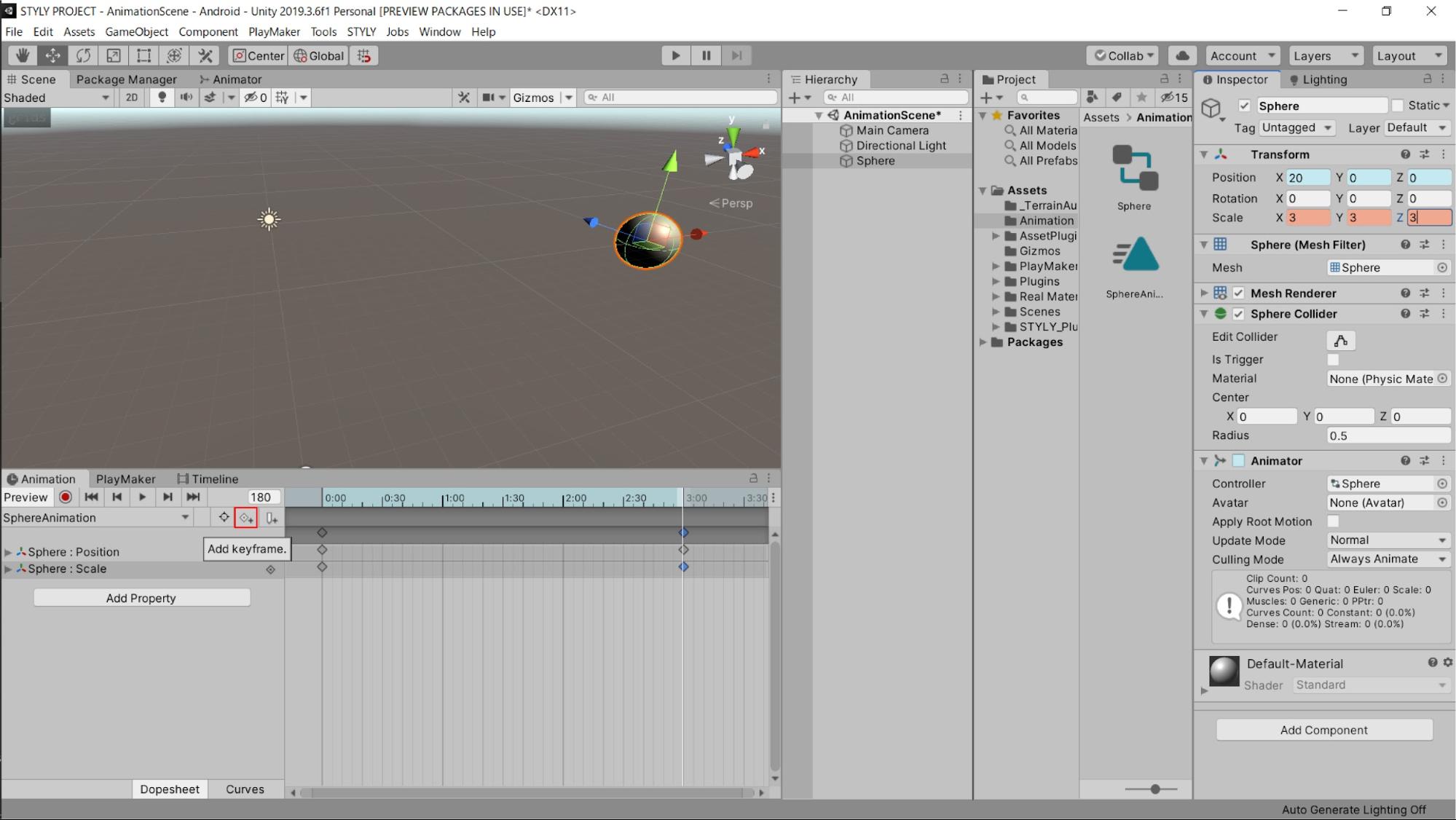
これでSphereの大きさが変わるアニメーションの設定が完了しました。
実際に確認しましょう。
Sphereが移動するのに加えて、大きさも変わるアニメーションが設定されました。
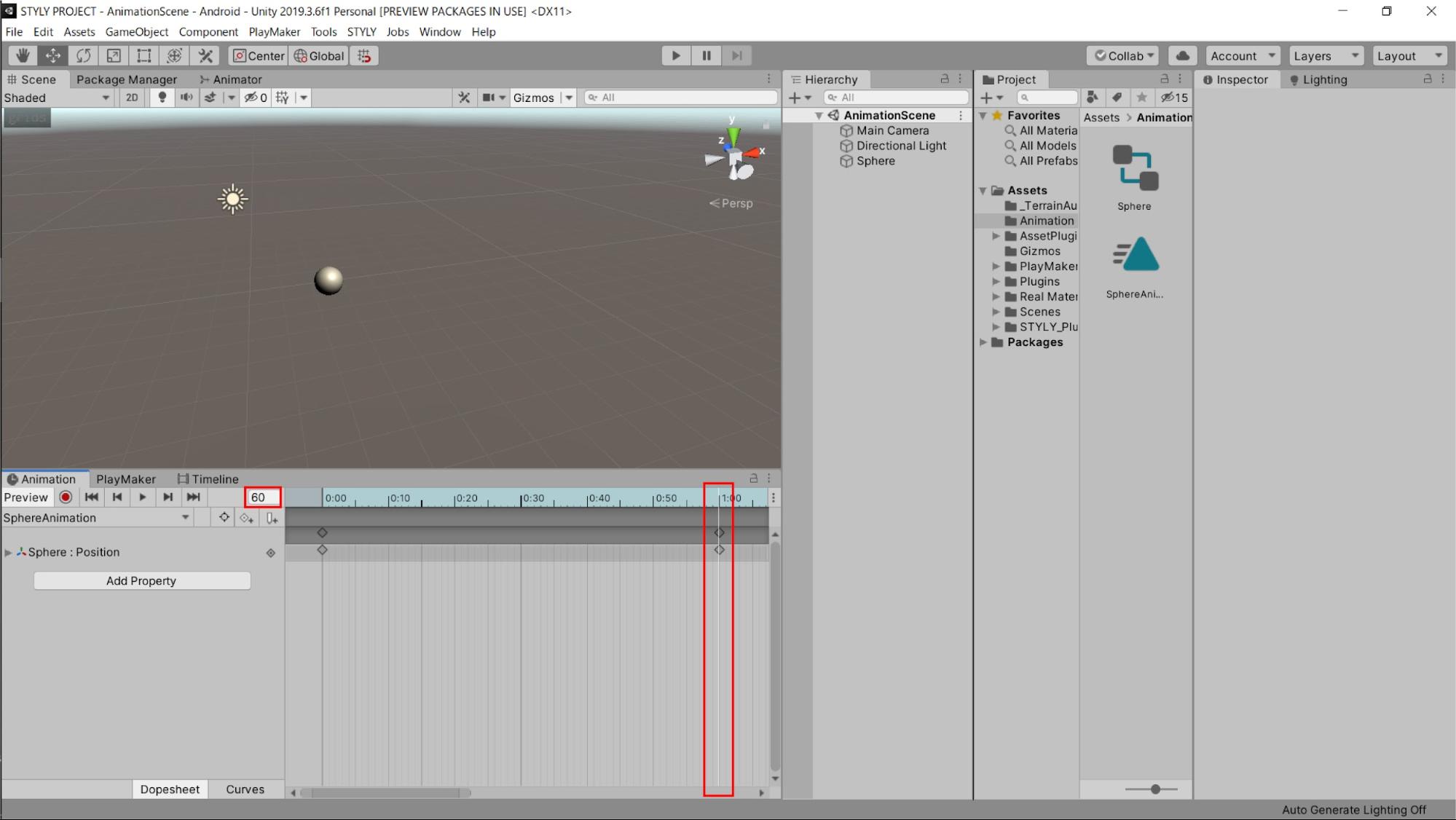
最後に、アニメーションの時間の長さを変えてみましょう。
グラフ上のキーの位置を変えることでアニメーションの長さを変えることができます。
一番上のキーを3:00の位置から、5:00の位置に変えましょう。
一番上のキーはその縦軸の項目をすべて動かすことができます。
今回はPosition、Scaleともに変化させるために一番上のキーを動かしました。
各項目のキーを動かすこともできますので試してみてください。
実際にアニメーションを再生してみましょう。
先ほどよりゆっくりとしたアニメーションになりました。
このようにキーの位置を変えることで、アニメーションの長さを変えることができます。
アニメーションをループさせる
アニメーションが完成した3Dモデルを、実際にシーンで再生してみましょう。
シーンで再生する場合は、アニメーションウィンドウの再生マーク(▶)を選択するのではなく、一番上の再生マークを選択しましょう。
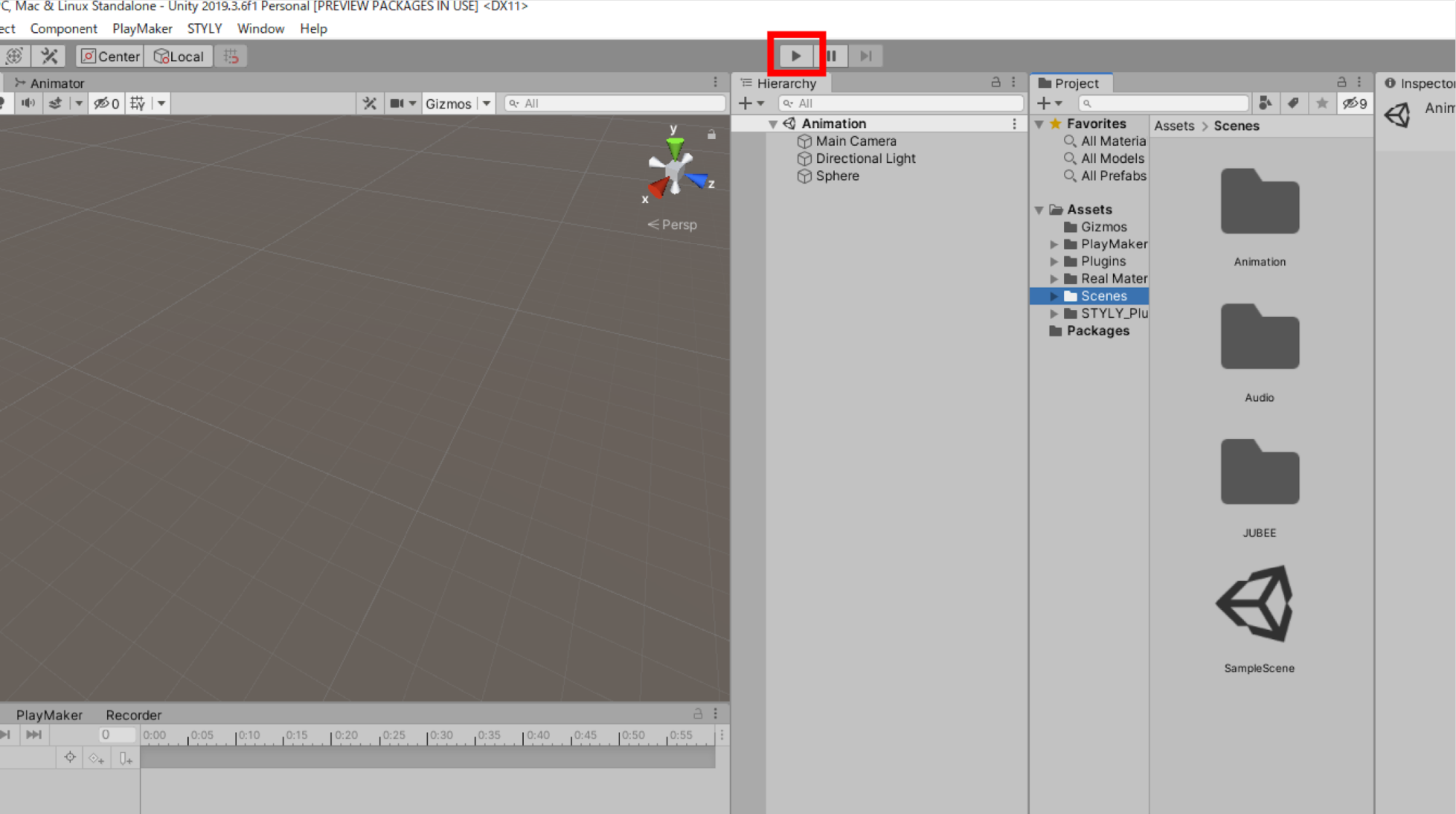
するとシーンが再生されます。
このようにアニメーションがループしています。
これは、Animation Clipの設定がループになっているためです。
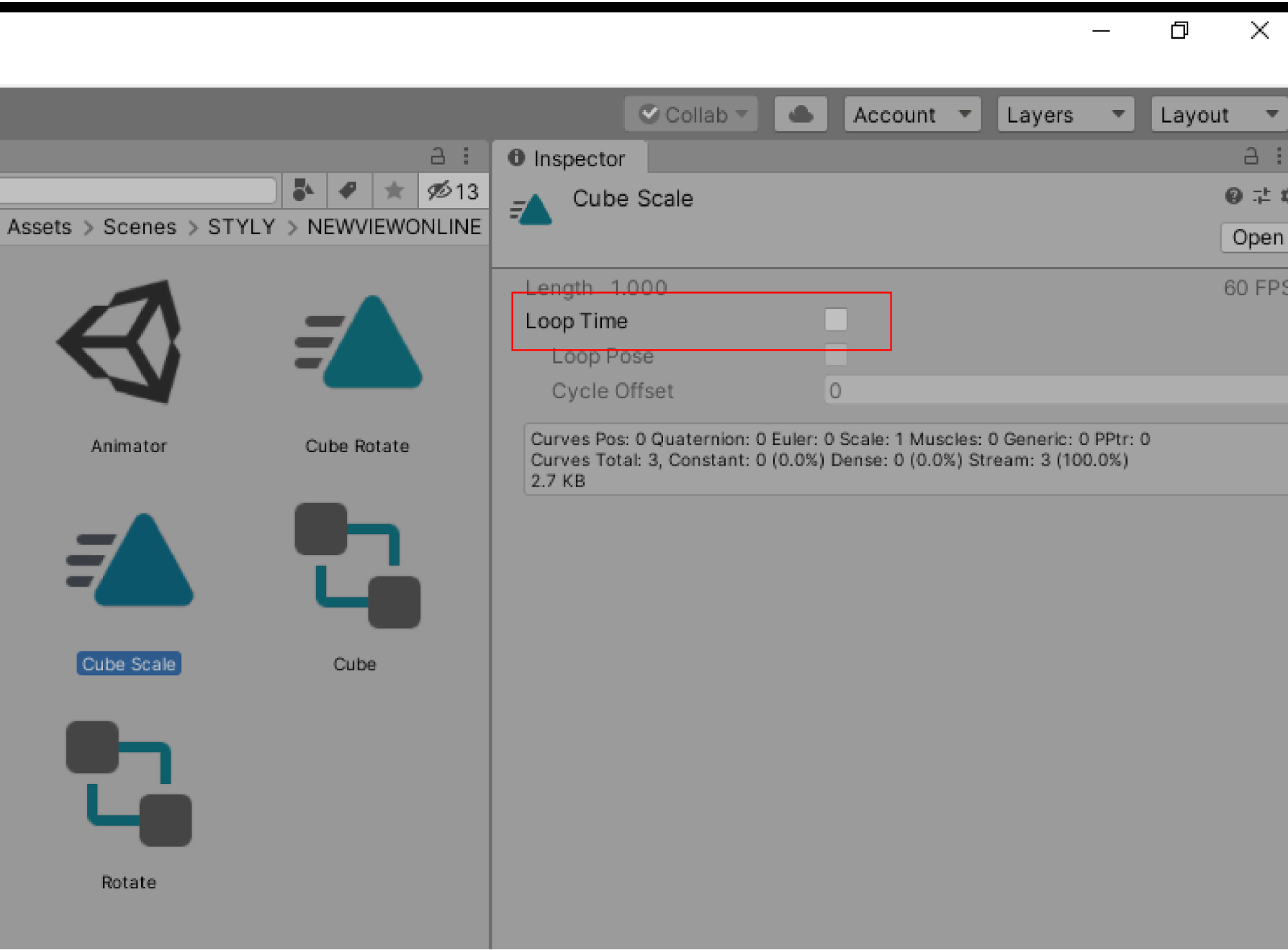
プロジェクトウィンドウ内の「SphereAnimation」を選択し、インスペクターを確認しましょう。
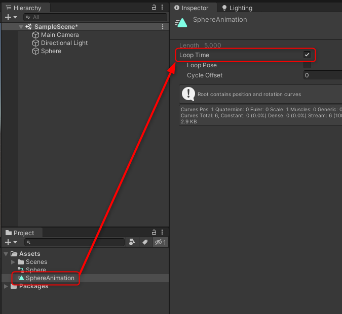
アニメーションがループするのはこのLoop Timeにチェックマークが入っているためです。
このLoop Timeを外すとループしなくなります。
必要に応じて設定しましょう。
サンプルシーン
今回学んだことと、STYLYの既存のオブジェクトだけで、以下のようなシーンを作れるようになります。
<iframe height=”360″ width=”640″ frameborder=”0″ src=”https://gallery.styly.cc/embed?g=a133cd65-90e8-11ea-834c-06540631ffe6″ allowfullscreen=”allowfullscreen”></iframe>
アニメーションを3Dモデルに加えるだけで、没入感が増した空間を作ることができます。
いろいろなアニメーションを加えてみて、素敵な演出をしてみましょう。
2D作品にアニメーションをつける
作品をインポートする
アニメーションの基礎を利用して、自分が制作した作品をUnityにインポートし、アニメーションをつけてみましょう。
最終的に、以下のように写真などの2D作品にアニメーションをつけられるようになることを目指します。
最初に、自分が制作した作品をUnity内にインポートしましょう。
Unityは以下の2Dフォーマットに対応しています。
- BMP
- EXR
- GIF
- HDR
- IFF
- JPG
- PICT
- PNG
- PSD
- TGA
- TIFF
また、3Dフォーマットでは以下に対応しています。
- fbx
- dae(Collada)
- 3ds
- dxf
- obj
使用するデータは自由に選んで大丈夫ですが、手元に使用するデータがない人のために、今回は使用する写真のデータを添付します。
サンプルとして使用してください。
作品をUnityにインポートしましょう。
Unityの画面を立ち上げ、上のメニューバーの「File」の「New Scene」を選択して、新しいシーンを立ち上げましょう。
作品データを格納するためのフォルダを用意します。
プロジェクトウィンドウのAssetsフォルダを右クリックして、画像を格納する新規フォルダを作成してください。
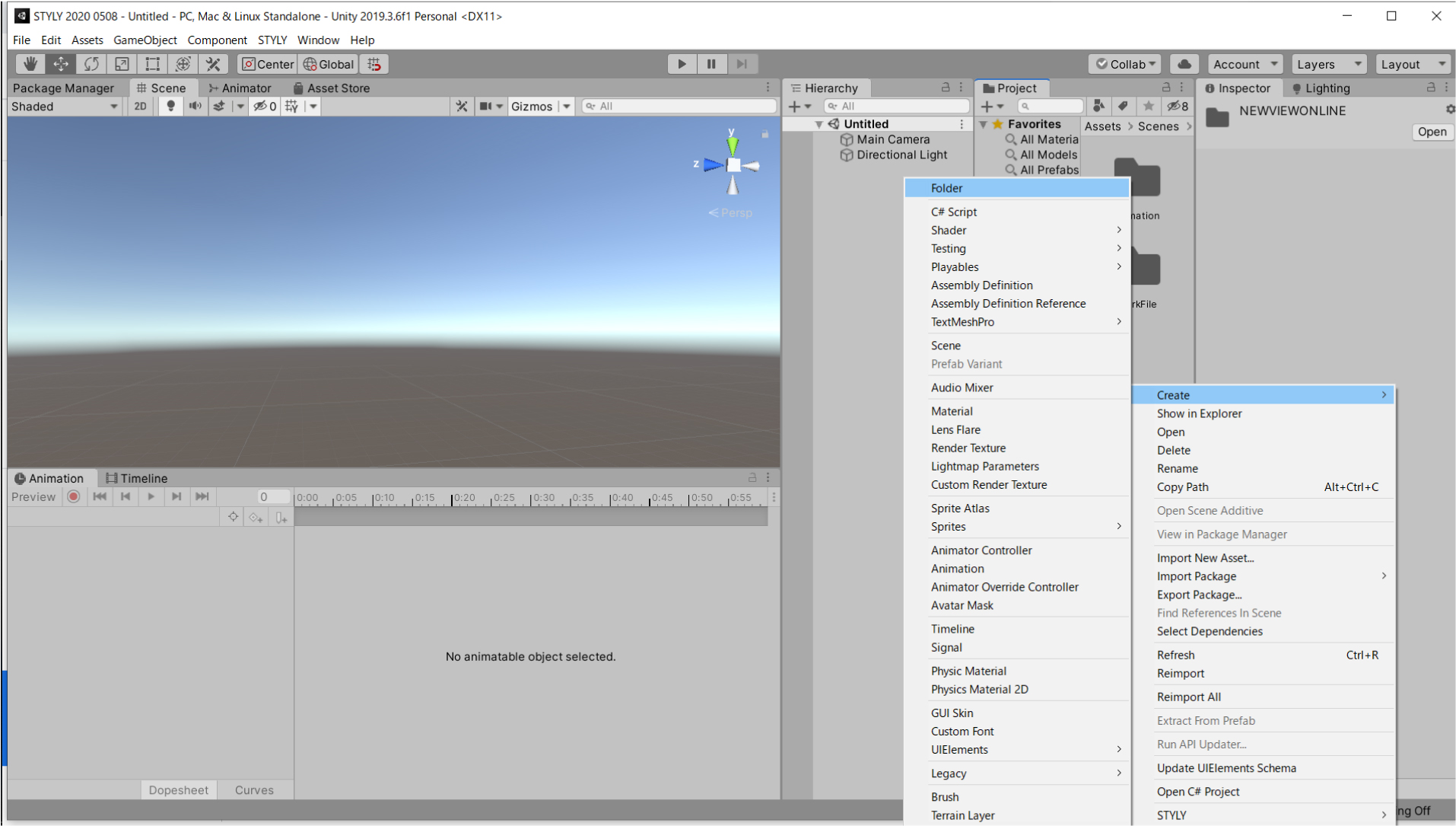
New Folderを作成したら、名前を「WorkFolder」に変更しましょう。
このフォルダ内に作品をインポートします。
フォルダ内で右クリックをし、メニューバーの「Import New Asset…」を選択します。
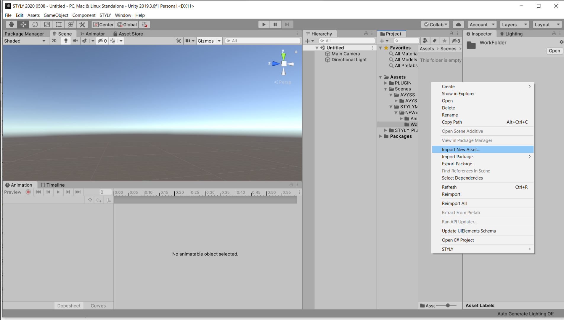
フォルダのウィンドウが表示されますので、今回インポートする作品を選択しましょう。
プロジェクト内に表示されたら、インポート完了です。
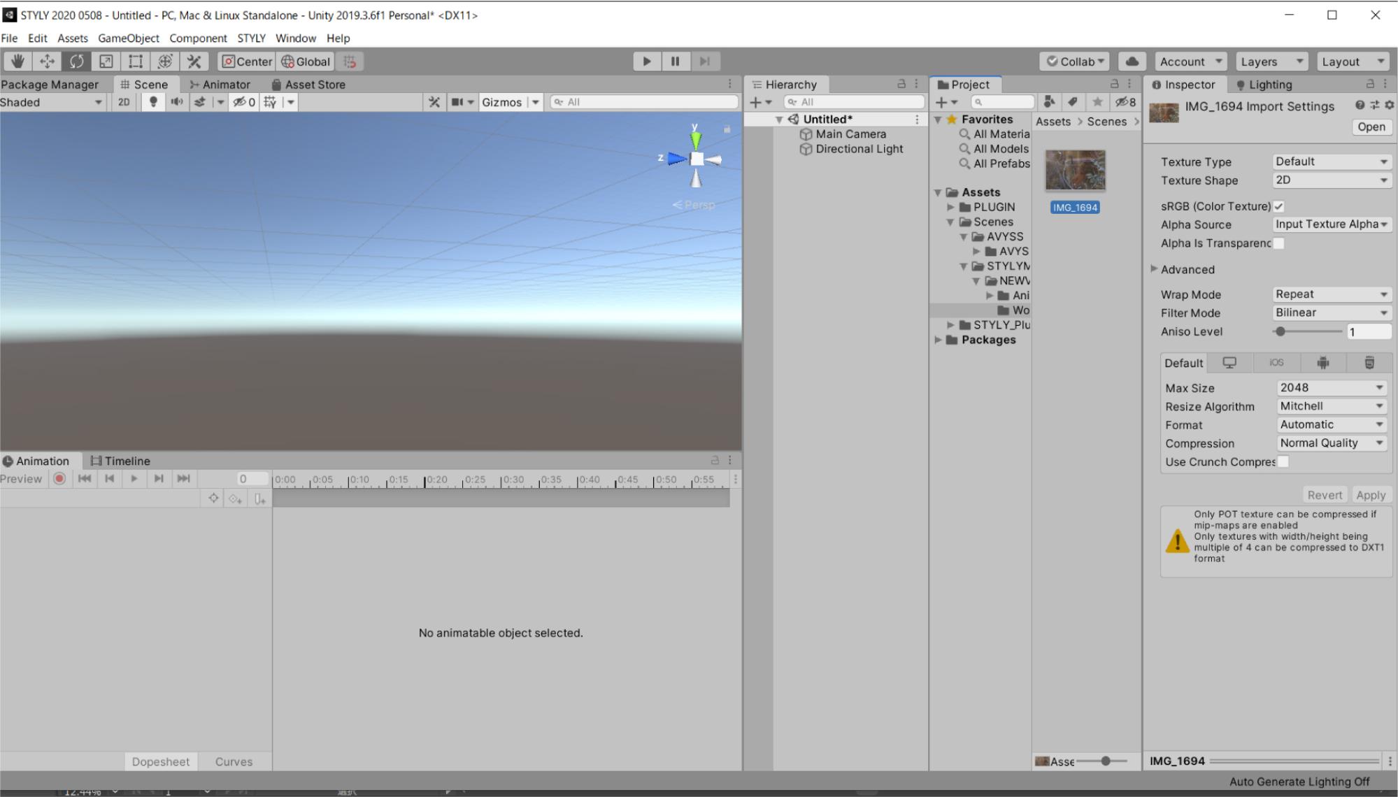
このままの状態ではシーン内に配置することはできません。
作品をインポートするには、作品のTexture Typeを変更する必要があります。
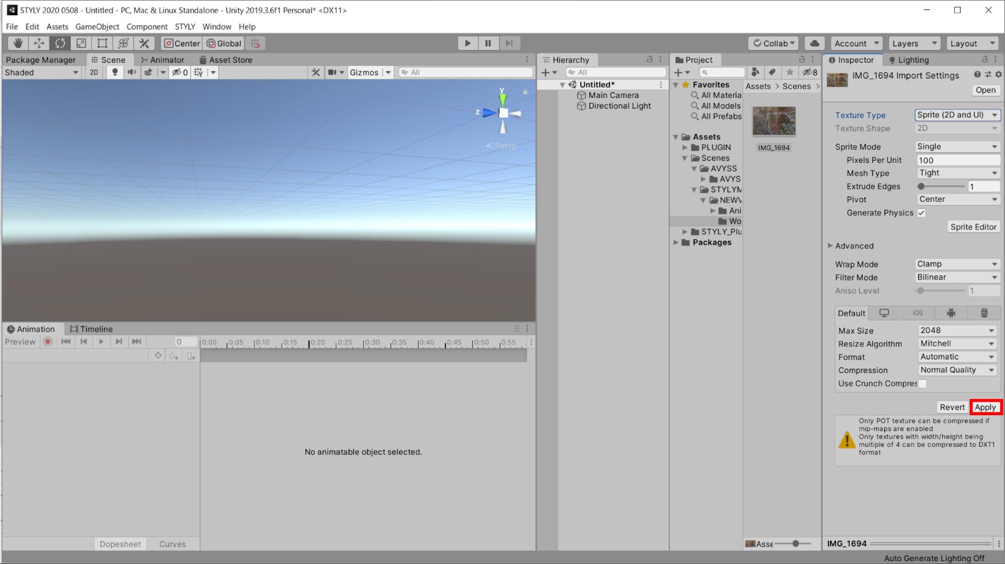
プロジェクト内の画像を選択した状態で、インスペクターのTexture Typeのメニューバーを選択します。
隠れていたメニューが表示されたら、DefaultからSprite 2D and UIに変更してください。
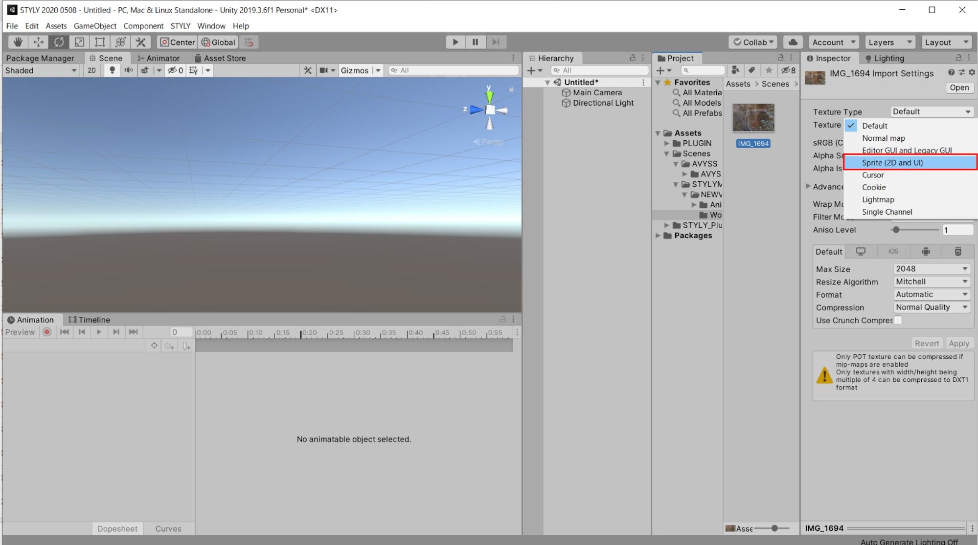
Texture Typeを変更したら、インスペクターの右下Applyを選択しましょう。
Applyを選択しないと、変更した内容が反映されないので、注意しましょう。
画像をシーン内に配置できるようになりましたので、シーン内にドラッグ&ドロップしましょう。
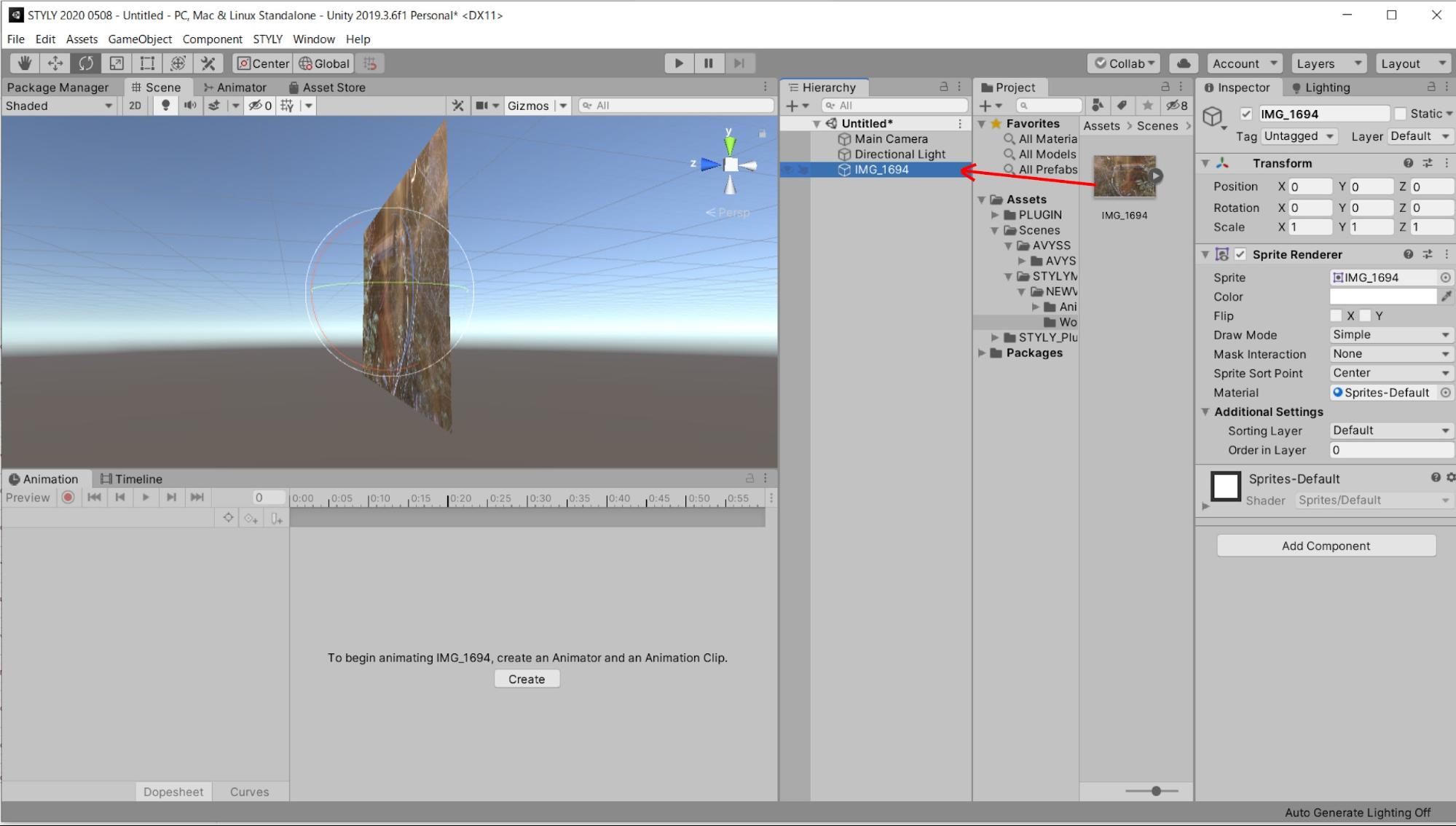
シーン内に作品を配置することができました。
画像オブジェクトにアニメーションを付けましょう。
アニメーションをつける
画像に回転するアニメーションを設定します。
作品オブジェクトを選択した状態で、アニメーションウィンドウでCreateを選択しましょう。
ファイル名は、2DAnimation.animにします。

Add Propertyの欄はTransformのRotationを選択します。

初期状態で設定されている右の1:00のキーフレームを削除します。
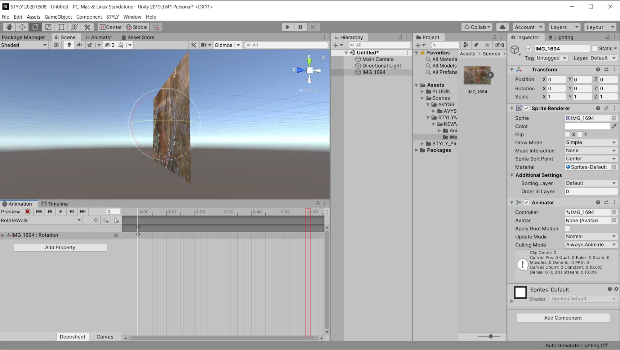
5:00のキーフレームにアニメーションを設定しましょう。
5:00の位置にグラフをもっていき、インスペクター画面上のTransformのRotationのYの値を360にします。
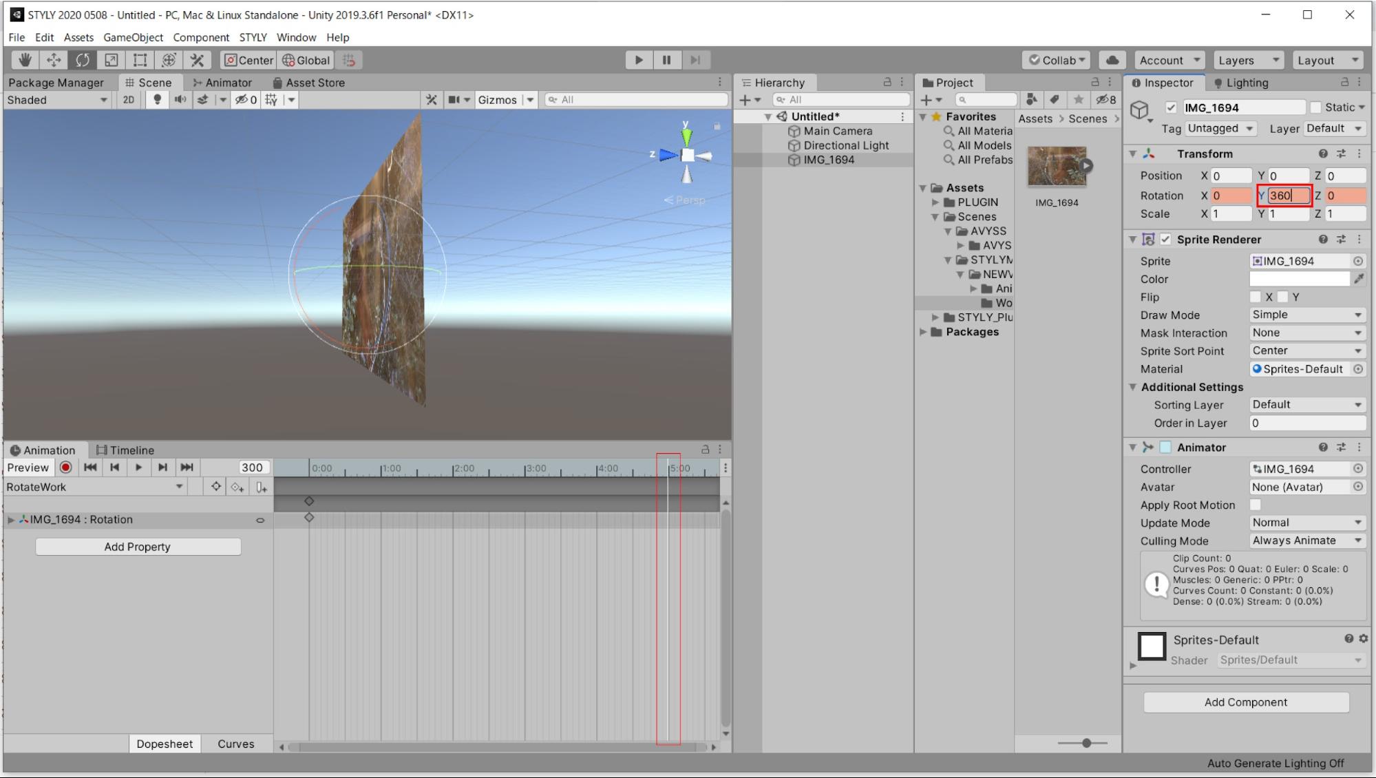
この状態で5:00の位置にAdd Keyframeを選択しましょう。

キーが打たれたらアニメーションの設定が完了です。
このアニメーションは5秒間でY軸を軸に1回転するアニメーションです。
再生してみましょう。
アニメーションウィンドウの再生ボタンを押します。
このようにUnity内に写真やイラストなど2Dで制作したものを取り込み、アニメーションをつけることで、また新しい見え方ができるようになるはずです。
今まで極めてきた領域の作品を上手く有効活用し、VR/AR作品制作に取り組んでみましょう。
Animator Controllerを理解する
アニメーションを作成する
Unityには、キャラクターや3Dモデルのアニメーション効果を実装するAnimator Controllerという機能があります。
Animator Controllerは複数のAnimation Clipを制御しており、これを利用することでAnimation Clipを切り替えたり、複数のアニメーションを組み合わせたりといったことが可能になります。
Animator Controllerを学ぶことで、Unityのアニメーションをより高度に扱えるようになります。
このようなアニメーションを実行するシステム全体を「Mecanim」と称します。
今回は、「Cubeを回転させ、大きくする」という複数のアニメーションを組み合わせる方法を例に説明し、Animator Controllerの基本的な使い方とMecanimの仕組みを解説します。
新規シーンを制作して、ヒエラルキーにCubeを配置してください。
ヒエラルキー上でCubeを作成したら、Position / Rotationの値をすべて0に、Scaleを1にしましょう。
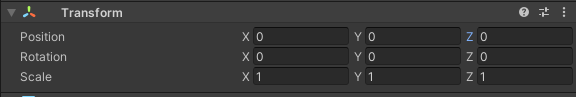
Cubeにアニメーションを作成して、Animator Controllerで制御します。
回転するアニメーションを作成します。
Cubeを選択した状態で、アニメーションウィンドウのCreateを選択しましょう。
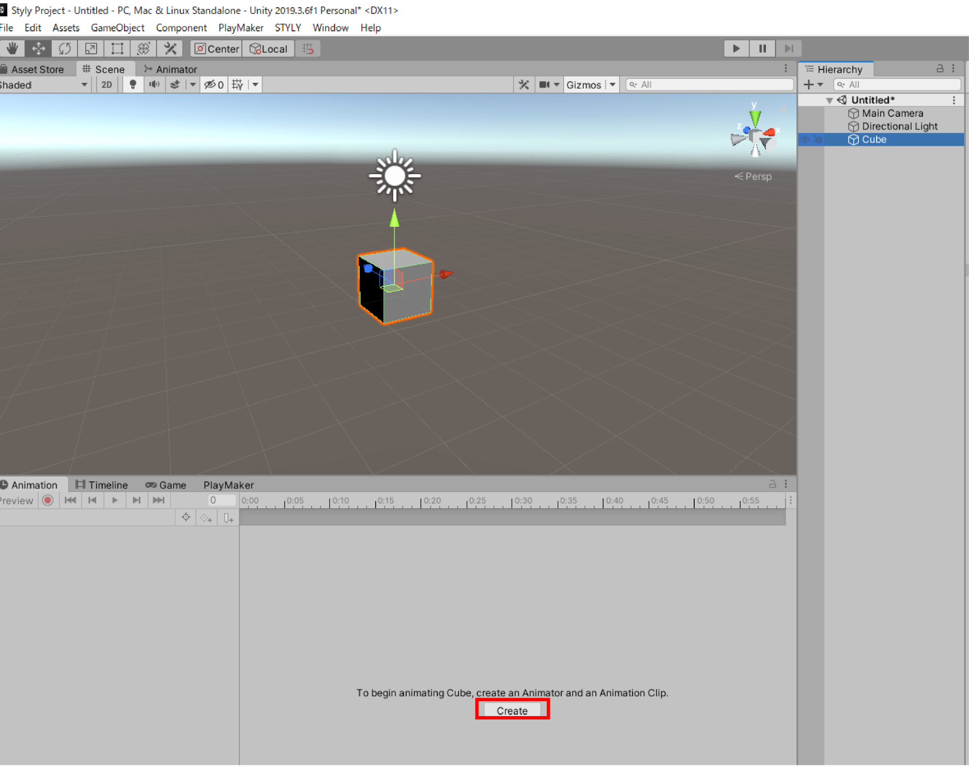
ファイル名:CubeAnimation.anim で保存します。
Assetsフォルダ内にAnimatorというフォルダを作り、Animatorフォルダ配下にCube.controller、CubeAnimation.animを移動します。
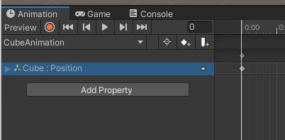
プロジェクトウィンドウ内にCubeAnimationのAnimation Clipが作成されました。
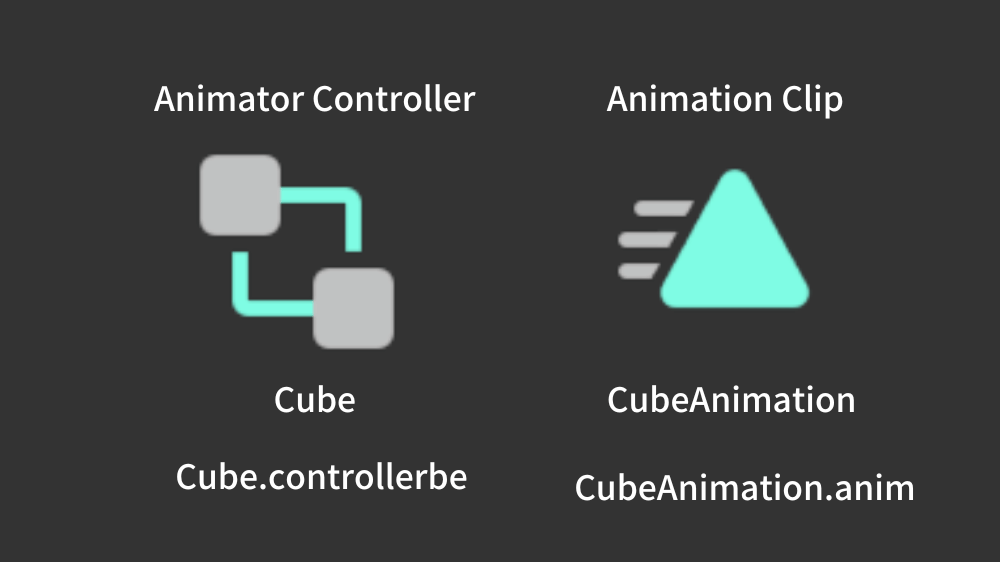
CubeAnimationの上にCubeの名のファイルも作成されています。
これがAnimator Controllerです。
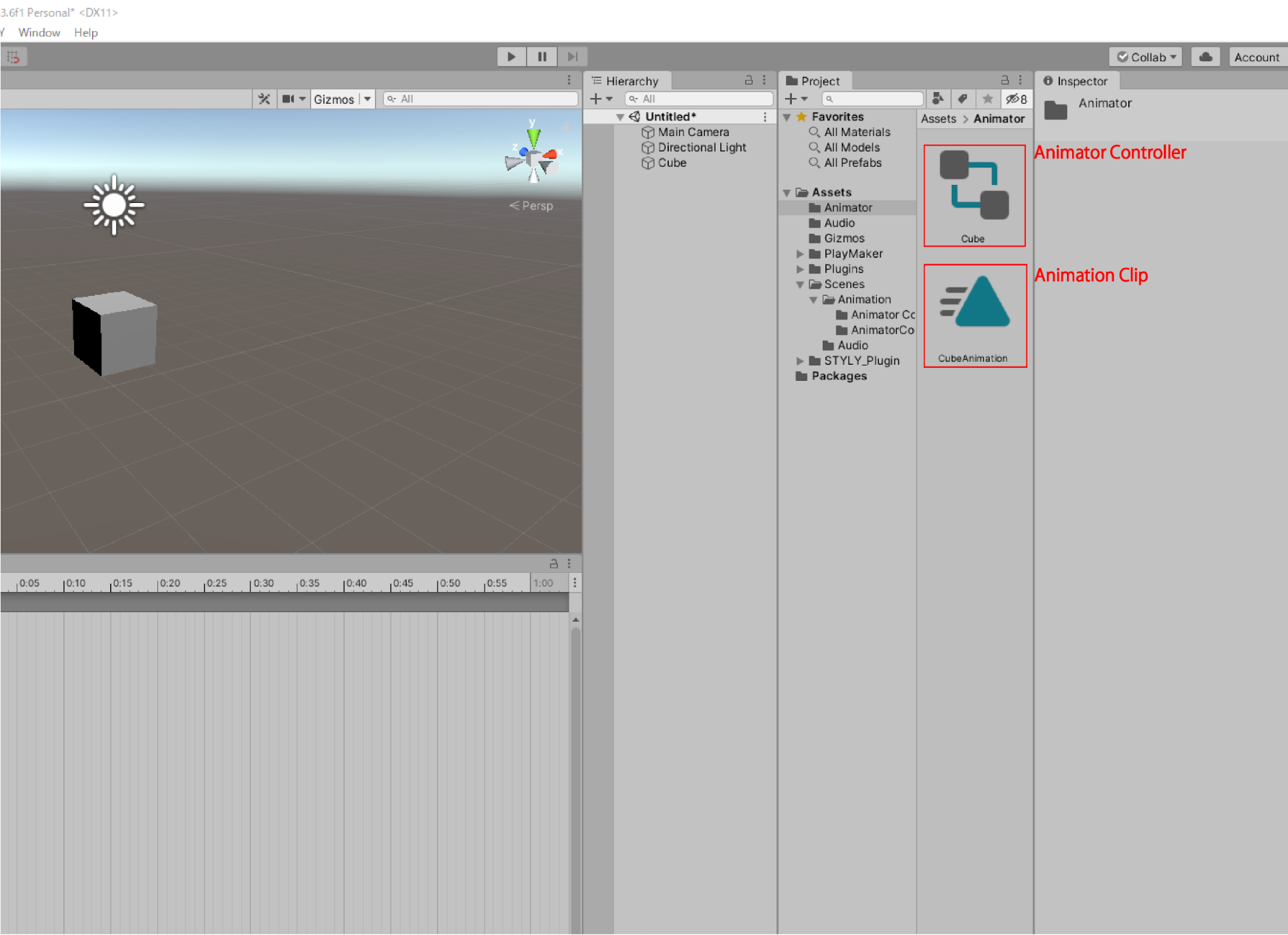
Cube.controllerbeは、Animatior Controller
CubeAnimationは、Animation Clip
Animation ClipのCubeAnimationを選択し、アニメーションウィンドウを表示させます。
アニメーションウィンドウを表示させたら、ヒエラルキー上のCubeを選択した状態で、アニメーションウィンドウのAdd Property → Transform →Rotationの+ボタンをクリックしてください。
1:00のキーフレーム箇所のRotationYのを360に変更してください。
Add keyframeをクリックします。
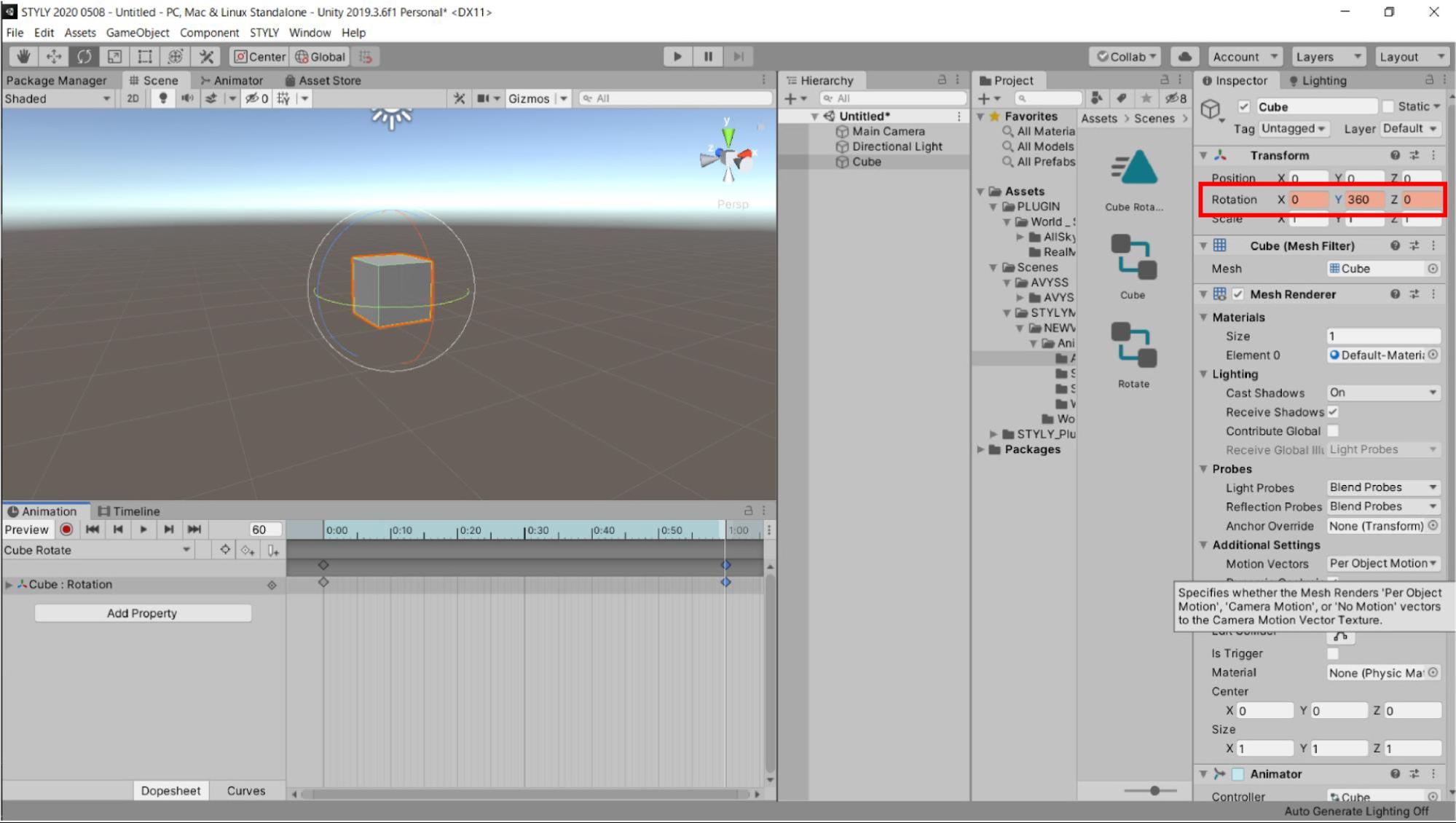
Cubeが1秒間でY軸を中心に1回転(360°回転)する設定です。
上の「▶」を押してSceneを実行してみましょう。
設定通り、Y軸を中心に1回転するループアニメーションができました。
次はCubeが大きくなるAnimation Clipをつくります。
同一のモデル上で別のアニメーションを作る方法を説明します。
先ほどCubeAnimationのAnimation Clipを作った同じCubeを選択します(ヒエラルキー上のCube)。
すると、アニメーションウィンドウでは「CubeAnimation」のアニメーションが表示されています。
その状態で、アニメーションを選択するタブが左上にあります。そのタブを選択して、「Create New Clip…」を選択しましょう。
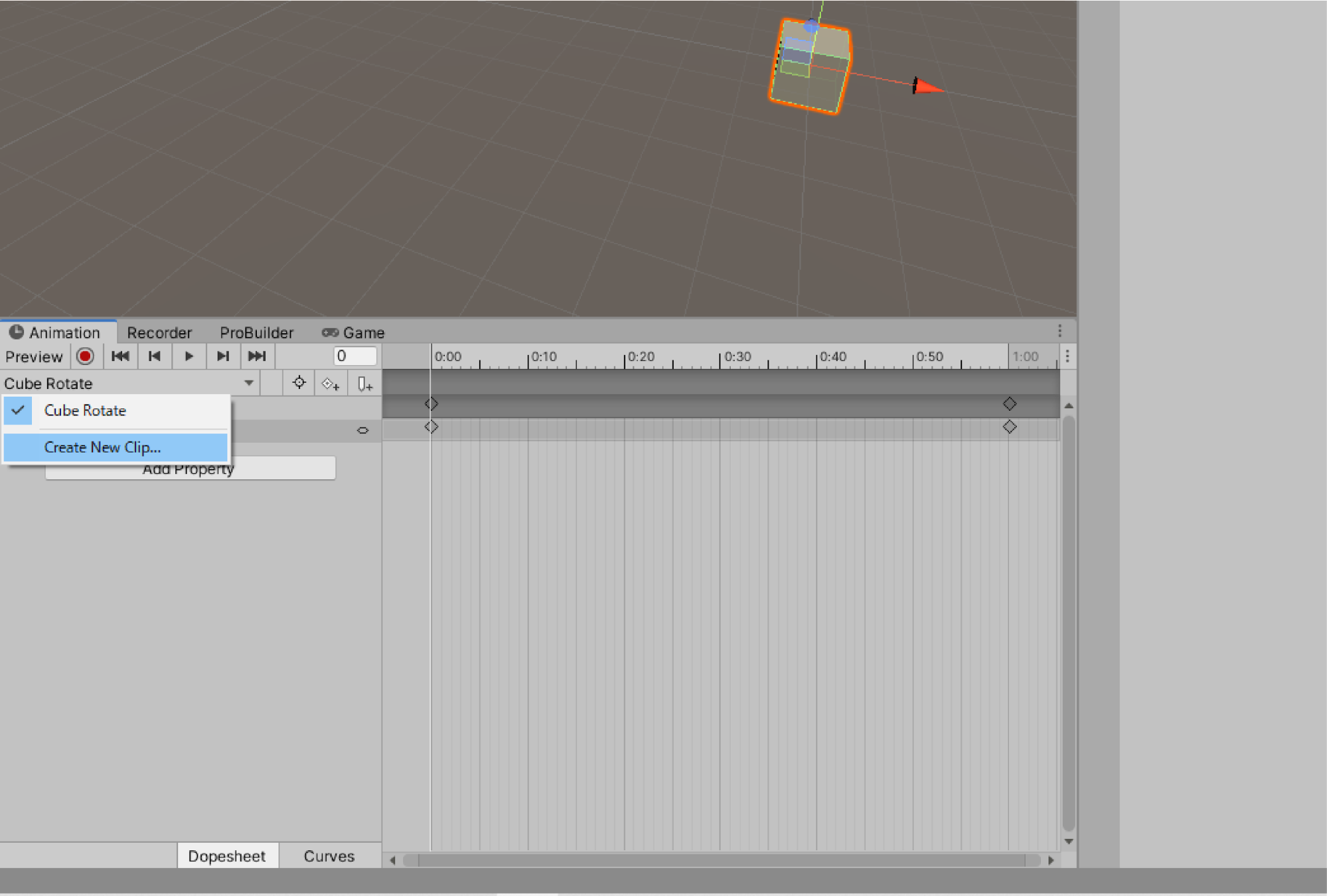
すると、ファイル保存ダイアログが表示されます。任意の場所にAnimation Clipを保存しましょう。
ファイル名はCubeScaleにします。
今回は1秒でCubeのScale X,Y,Zが5,5,5になるようなアニメーションをつくります。
アニメーションの設定の復習を兼ねて実際に設定してみましょう。
画像のような状態にします。
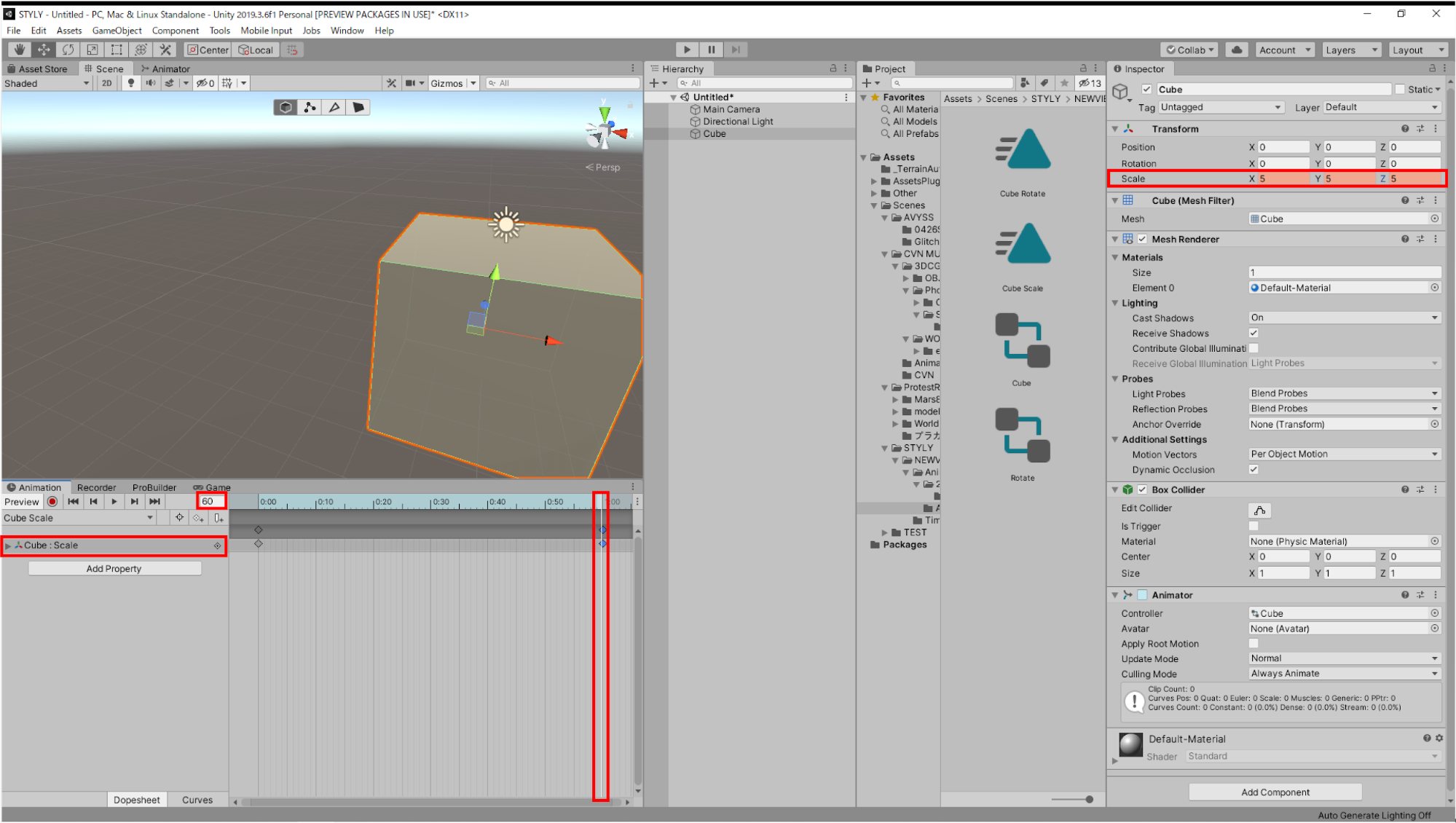
これで大きさが変わるアニメーションが作れました。
この状態でSceneを再生をしてみましょう。
Cubeは大きさは変わらず、先ほど作成した回転するアニメーションが再生されます。
Cubeの大きさが変わるアニメーションを制御するには、Animator Controllerを制御する必要があります。
Animator ControllerでAnimation Clipを切り替える
アニメーションは、複数の要素を組み合わせることによって成立しています。
この全体の仕組みをMecanimと呼びます。
前のセクションで使用したAnimation Clipや、これから学習するAnimator Controller、AnimatorコンポーネントはMecanimを構成する要素となります。
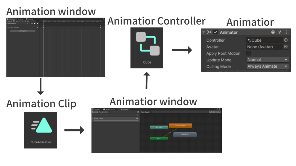
Animation Clip
- アニメーションウィンドウで作成したアニメーションのデータが入ったファイル
- 拡張子.animのファイル
- 外部も可能(Unity内で作成可能)
- Animation Clipのアニメーションデータはアニメーションウィンドウで編集する
Animator Controller
- Animation Clipを再生するシステム
- オブジェクトの状態(State)とその遷移(Transition)を管理するアセット(StateやTransitionは後程説明します)
- Animation ClipをStateに格納し、遷移の組み合わせによって複数のアニメーションを制御することができる
- 拡張子.controllerのファイル
- Animator Controllerはアニメーターウィンドウ上で編集する
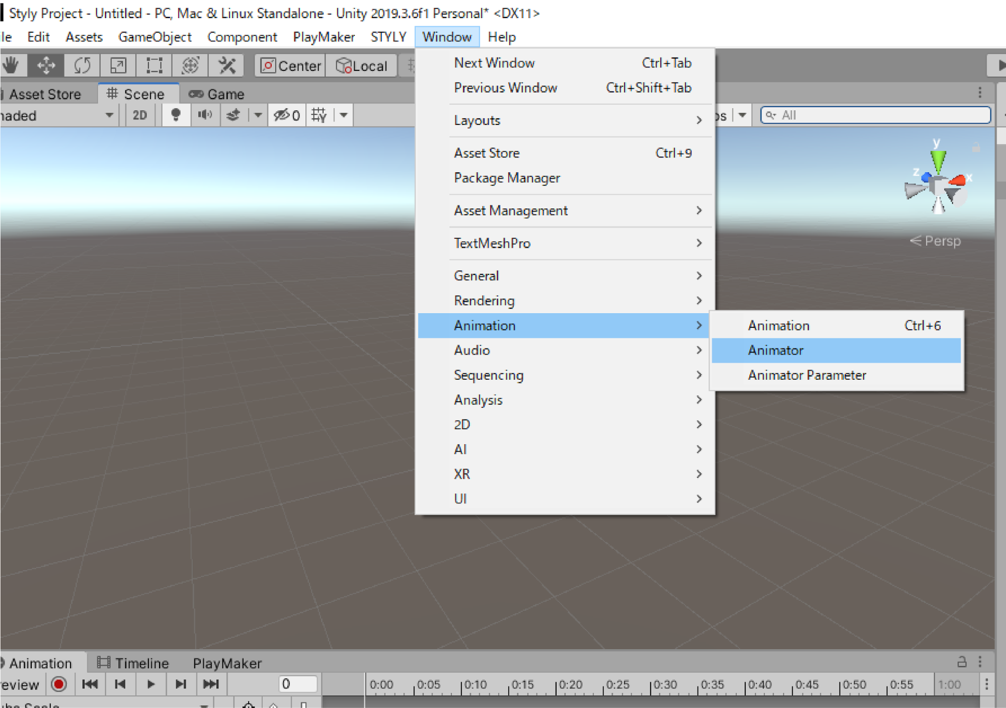
アニメーターウィンドウは、メニューバーのWindow > Animation > Animatorで表示されます
Animator
- アニメーションさせるオブジェクトにアタッチするコンポーネント
- このコンポーネントのControllerプロパティにAnimator Controllerを設定する
- Animator Controllerが設定されないと、アニメーションは実行されない
- Animatorコンポーネントは、加えたいオブジェクトを選択し、インスペクター画面よりAdd Componentから追加できる
このシステムが成立することによってアニメーションが実行されます。
Cube Scaleのアニメーションが実行されなかったのは、アニメーターウィンドウ上でCubeAnimationのみを実行する、という組み方がされているためです。
これを編集し、Cube Scaleを実行する、という組み方に変える手順を説明します。
最初にアニメーターウィンドウを表示します。
上記メニューのWindowよりAnimation > Animatorを選択しましょう。
アニメーターウィンドウが開かれるので任意の位置に配置します
次に、「Cube」のAnimator Controllerをダブルクリックしましょう。
すると以下のような画面になります。
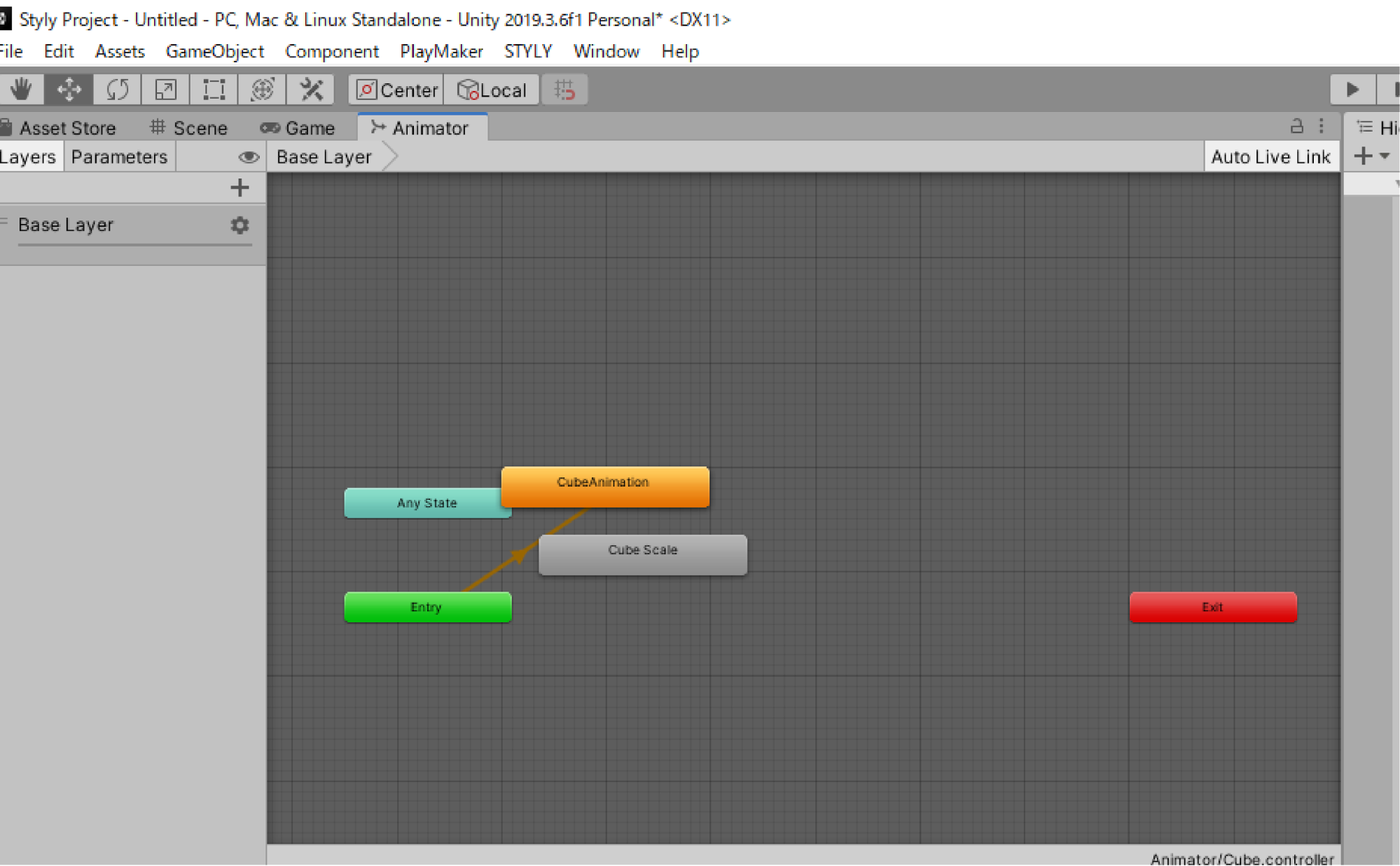
これがアニメーターウィンドウになります。
一つ一つの四角形がStateとなります。
Stateとはアニメーションクリップを格納し様々な設定をする機能です。
Stateの設定を調整することで、アニメーションの設定をすることができます。
「Entry」のStateから「CubeAnimation」のStateに矢印が伸びています。
これをTransitionと呼びます。
Transitionはアニメーションの遷移を指定するものなので、上の画像で言うと「Entry」の次に「CubeAnimation」のアニメーションが実行されます。
Stateの役割
ここで最初から用意されているStateについて、それぞれのStateの役割を簡単に解説します。
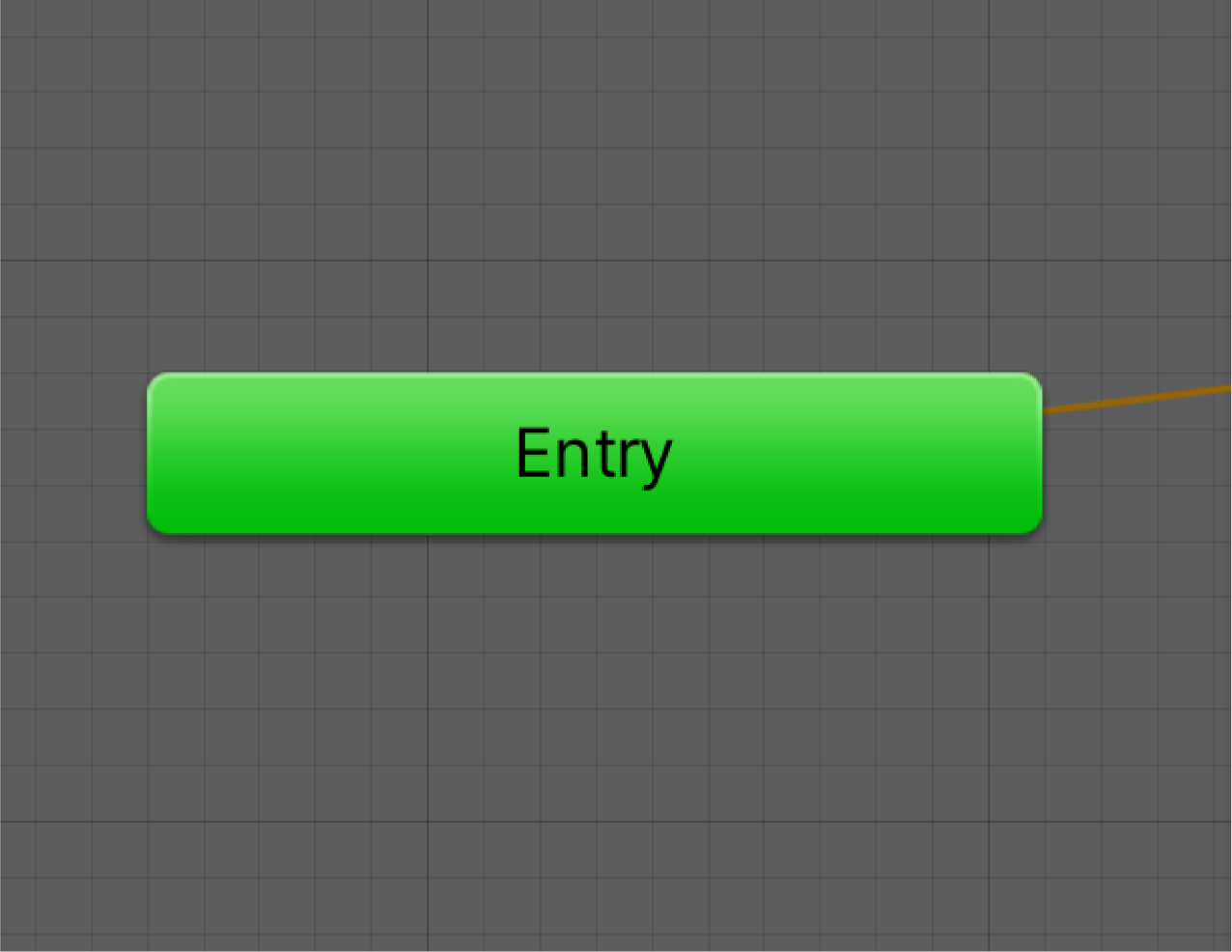
Entry
Entryは最初にアニメーションの遷移がスタートするStateです。
アニメーションの最初に設定したい動作はこのEntryから遷移させるようにしましょう。
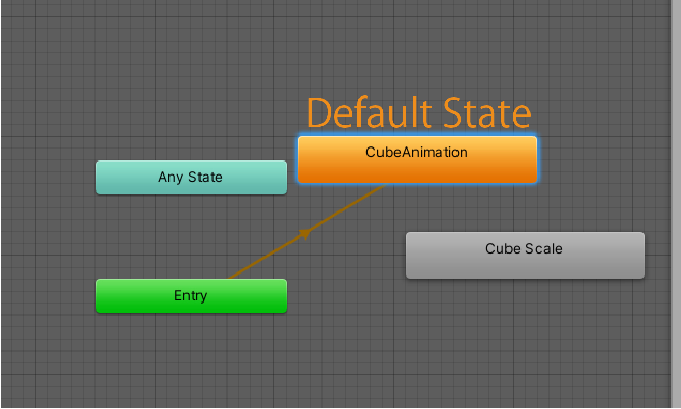
Entryから最初に遷移するStateのことをDefault Stateと呼びます。
Default Stateはオレンジ色の四角で表示されます。
下記画像の状態ではEntryから「CubeAnimation」に遷移しているため、CubeAnimationがDefault Stateとなります。
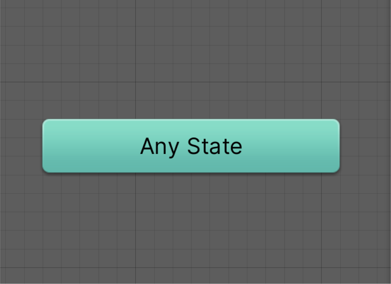
Any State
Any Stateはどの状態からでも好きな状態に遷移できるStateです。
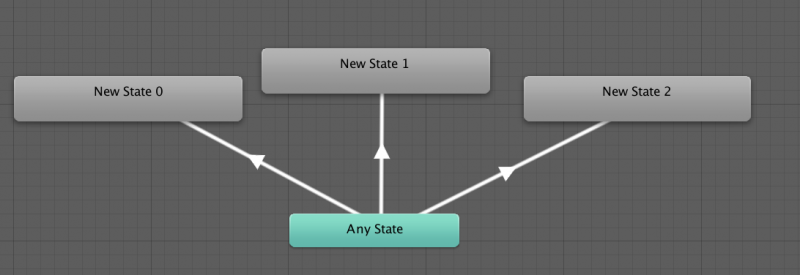
そのため、Any Stateから遷移を以下のように伸ばせば、好きなように遷移可能になります。
Exit
Exitに遷移するとアニメーションが終わります。
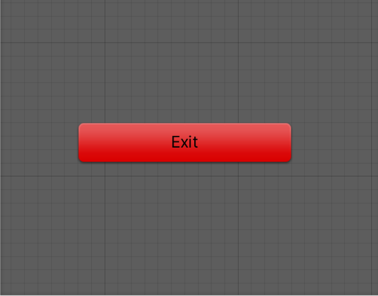
Any StateとExit Stateは今回は使用しませんが、このようなStateもあると理解していれば大丈夫です。
アニメーションを切り替える
Cube Scaleのアニメーションを実行させる手順を説明しながら、詳しいAnimator Controllerの使い方を解説します。
Animator Controllerが、現在は、「CubeAnimation」のStateがDefault Stateになっているため、CubeAnimationが実行されます。
このDefault Stateを切り替えることで実行されるアニメーションが変わります。
Cube Scaleを実行するためには「Cube Scale」のStateをDefault Stateにしましょう。
アニメーターウィンドウ上で、Cube Scaleを右クリックし、「Set as Layer Default State」を選択します。
すると、Cube Scaleがオレンジ色に変化し、Default Stateになります。
これで設定が完了です
シーンを再生し、Cube Scaleのアニメーションが実行されたら成功です。
複数のアニメーションを制御する
現在のAnimator Controllerの設定ではCube Scaleのみが実行されます。
つぎは、Cube Scale→CubeAnimationの順番に複数のアニメーションが実行されるようにします。
Cube ScaleのStateを選択し、右クリックをし「Make Transition」を選択します。
白い矢印が出現しますので、この矢印をCube AnimationのStateにつなげましょう。
これでAnimationのTransitionの設定ができました。
実際にアニメーションを見てみましょう。
シーンを再生し、Cube Scale→CubeAnimationの順番でアニメーションが実行されれば成功です。
もしCubeAnimationのアニメーションがループしてる場合、CubeAnimationのAnimation Clipに「Loop Time」がチェックマークついている可能性があります。
Loopさせたくない場合は、チェックを外しましょう。
以上がアニメーションが実行される仕組みとなります。