This is the eighth article in the Visual Scripting Introduction series. You can check out the previous article from the link below.
This article is part of a two-part series explaining how to create a shooting game using Raycast and List.
In this article (the second part), you will learn:
- Raycast
- Destroy
- Removing elements from a List
- How to use Tags
Using Raycast to Retrieve Object Information
A Ray is a beam of light emitted in a specified direction, and it can be used to obtain information about the objects it hits.
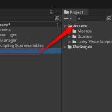
Add a GameObject type variable named [Camera] to the Variables.
Assign the MainCamera in the scene to the Value.
Add [Camera] to the Graph Editor.
![Add [Camera] to the Graph Editor](https://styly.cc/wp-content/uploads/2024/08/1-3.png)
Add [Camera] to the Graph Editor
Add the following to the Graph Editor:
- On Update
- Get Key Down
- If
- Get Mouse Position
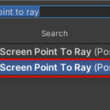
- Screen Point To Ray
- RayCast
※ Only unclear node images are provided.
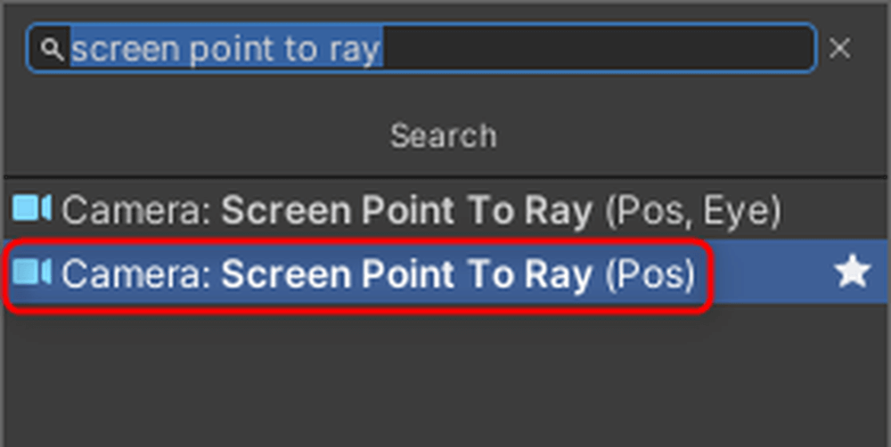
Screen Point To Ray
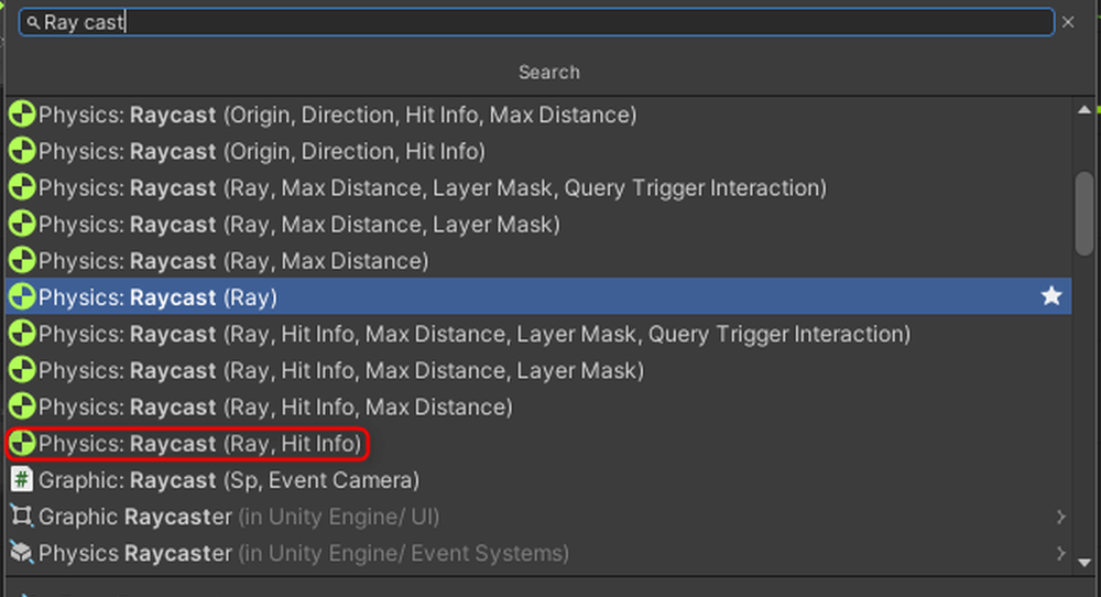
RayCast
Enter Mouse 0 (left-click) for the Key in Get Key Down.
The GIF shows what happens when you enter Mouse 0 for the Key in Get Key Down, which isn’t visible without scrolling.

Enter Mouse 0 in the Key field of Get Key Down
Connect the nodes as shown below.
By connecting the Camera component and Mouse Position to the left port of Screen Point To Ray, it creates Ray information from the camera. Connecting this to Raycast allows you to shoot a Ray.
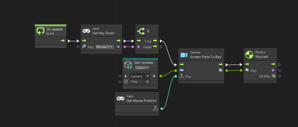
Connect nodes
Let’s confirm whether the Ray is being cast successfully.
Add the following nodes to the Graph Editor:
- Debug Log (Message)
- Get Collider
- Get Game Object
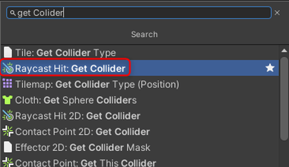
Get Collider
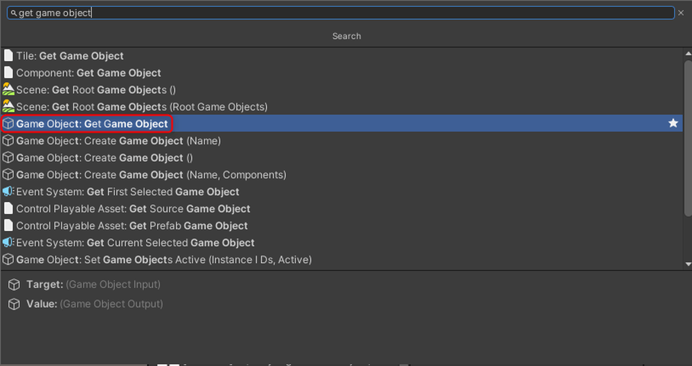
Get Game Object
Connect the nodes as shown below.
The Collider of the object hit by the Ray is obtained, and from there, the object’s information is retrieved to display the name of the target in the Console.
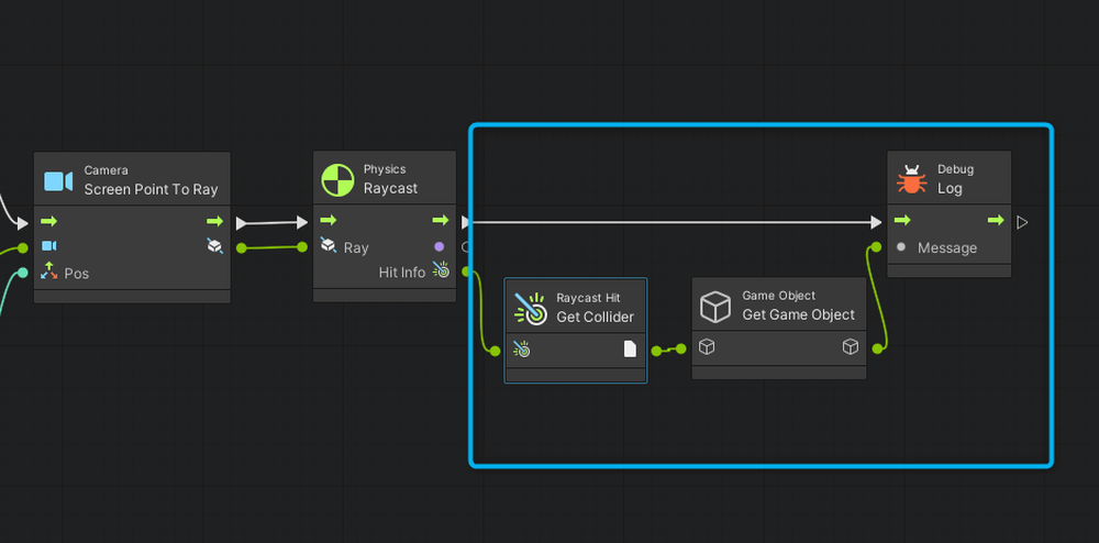
Connect nodes
Run the scene. You can display the name of the target you clicked.

Run the scene
Delete the Retrieved Object
As part of the game elements, let’s first create a floor.
Click the + button in the Hierarchy, then click 3D Object → Plane to create a Plane.
Set the Plane’s Transform as shown below.
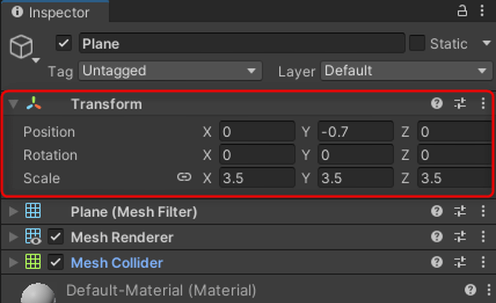
Set the Plane’s Transform
Next, register a new Tag to distinguish between the floor and targets.
Tags allow you to categorize objects, enabling you to change the processing based on the object’s Tag.
Click on the Tag of the [Target] prefab in the Project and then click Add Tag.
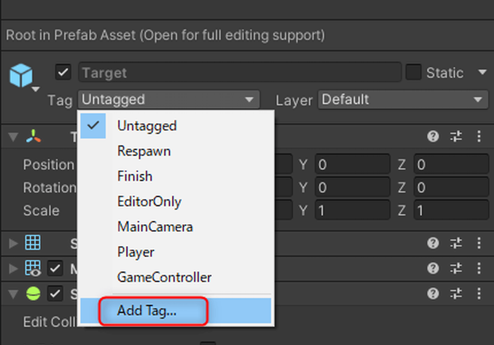
Click Add Tag
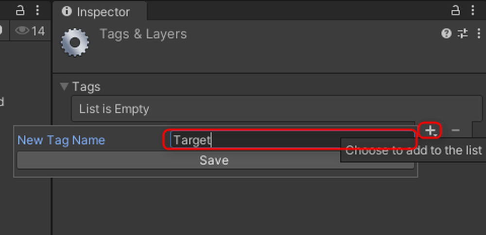
Click the + button, enter [Target] in the New Tag Name field, and then click Save.
This registers a new Tag.
Now, the [Target] prefab has the [Target] Tag, allowing you to perform operations based on this Tag.
Register a new Tag
Add the following nodes to the Graph Editor:
- If ×2
- String Literal
- Get Tag
- Equal
- Destroy
- Aot List Remove
※ Only unclear node images are provided.
Add [TargetList] from the Variables.
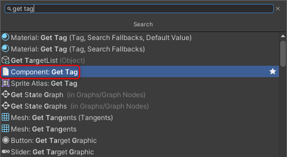
Get Tag
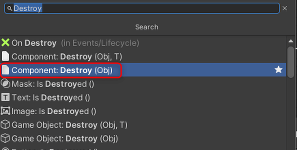
Destroy
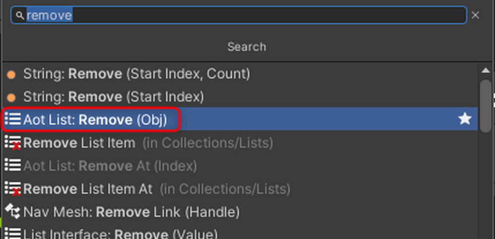
Aot List Remove
Connect the nodes as shown below. Enter “Target” in the String.
Here is an explanation of the nodes:
- The middle-right port of Raycast checks if the Ray hits an object. If it hits, it returns True; if it doesn’t, it returns False. In this case, if the Ray hits, the process moves to the next step.
- The Tag of the GameObject is retrieved, and if it matches [Target], it returns True, proceeding to the next step.
- The middle-left port of Remove connects to the list containing the object to be removed.
The bottom port connects to the object to be removed from the list.
If you don’t remove the object from the list before deleting it, an error may occur. Therefore, you remove the object from the list first, and then delete the object using the Destroy node by connecting the object to the bottom-left port.
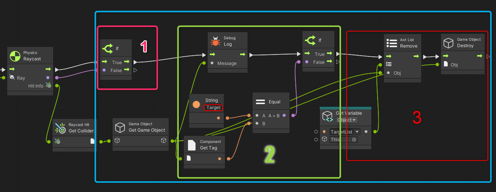
Connect nodes
Run the scene.

Run the scene
And with that, the project is complete. Below is an example that includes a scoring feature, which was created after reviewing Unity Visual Scripting tutorials in Parts 3 and 4.
If you have extra time, give it a try!

With scoring feature
![Introduction to Unity Visual Scripting Part 3: How to calculate time and score [Part 1 of the continuous hit game]](https://styly.cc/wp-content/uploads/2024/08/23-1-160x160.png)
![Introduction to Unity Visual Scripting Part 4: Switching screens and displaying scores [Part 2 of the continuous hit game]](https://styly.cc/wp-content/uploads/2024/08/11-1-160x160.png)
If you get stuck, you can check the completed sample here:
https://github.com/Manufuki/HitTargetSample.git
In the next installment, Part 9, we’ll cover how to play sounds and animations using Visual Scripting.