In this article, I will show how to create ‘a frame to show the world converted into cartoon’.
I think those who read this article for the first time cannot get it, so please watch the following Twitter video for reference.
https://twitter.com/OEKA_AKI/status/1115272322217271296
As seen in this video, the goal of this article is to show:
①The background converted into ‘cartoon’ when viewing through the frames
②A different object for each frame
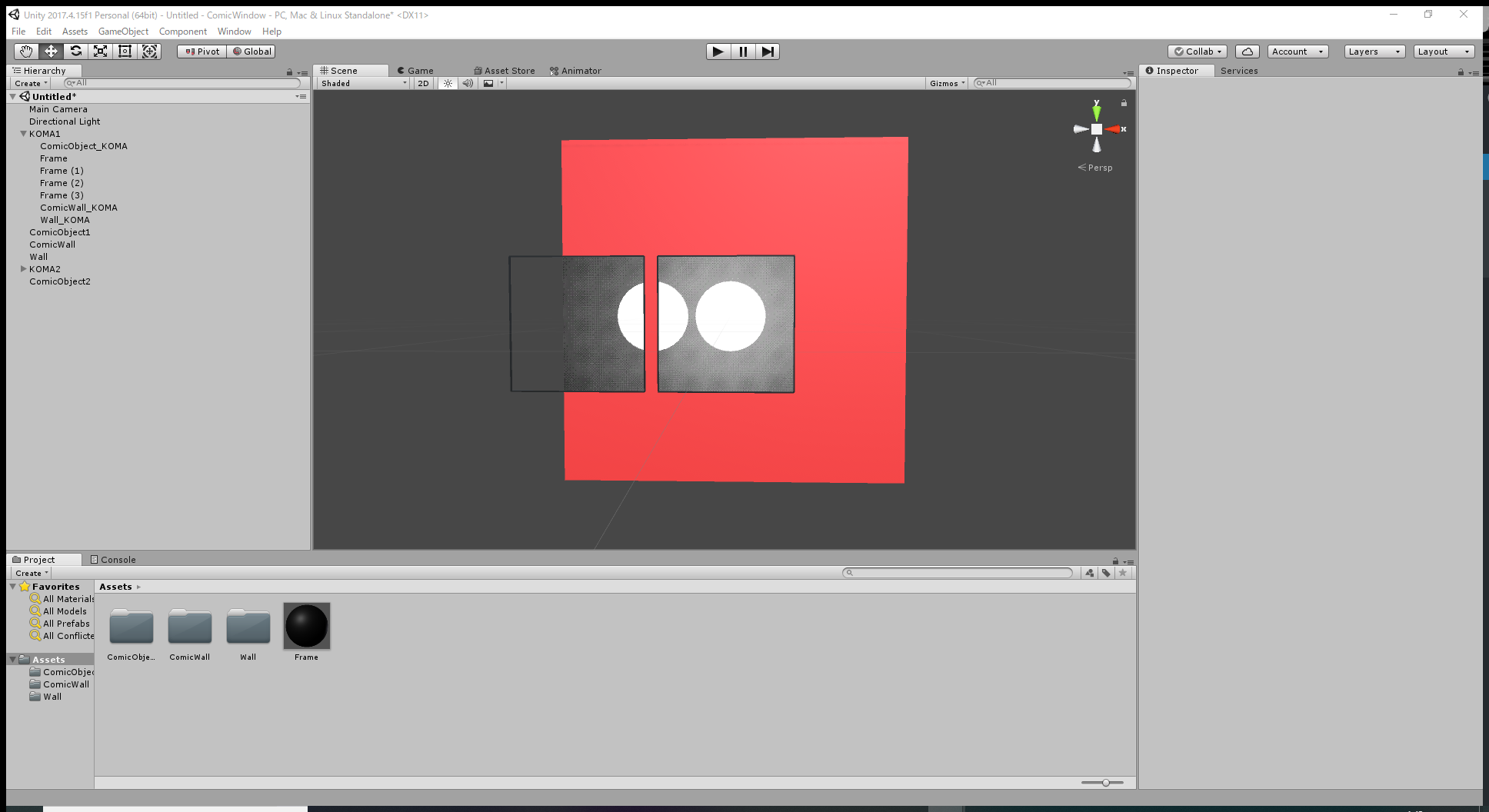
I will explain the method in a simplified way. The actual completion image at the end of this article is shown in the following image.
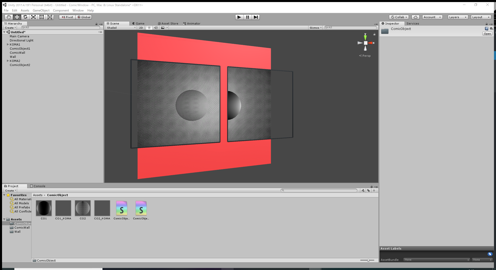
When viewing the red wall through the frames, you can see a cartoon-style wall and a different sphere for each frame.
Although I will take a simplified way, it still involves more data files and processes than usual.
I will explain how to do it at first and then explain how it works at relevant points.
In particular, it’s difficult to apply this method without knowing how to use shaders to a certain level. So let’s learn about them, too.
A brief explanation about the mechanism
I think it’s hard to follow each process without some knowledge, so I summarize the workflow here.
① Create a Wall as the background.
② Create a frame that makes the Wall transparent.

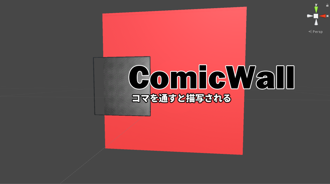
③ Create ‘ComicWall’ that is visible only through the frame.
④ Create a frame that shows a cartoon-style sphere (ComicObject1) so that it’s overlapped with the frame created in ②.
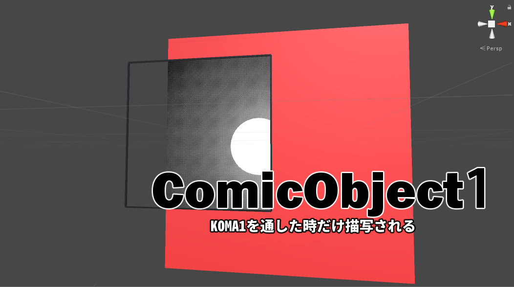
⑤ Create ‘ComicObject1’ that is displayed only through the frame.
⑥ Duplicate the frame.
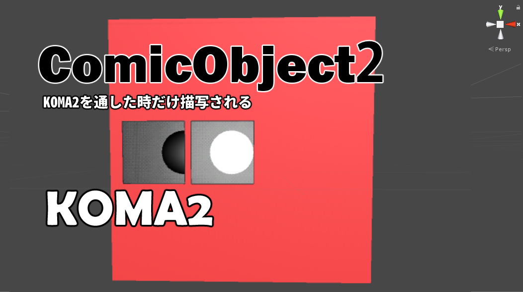
⑦ Create ‘ComicObject2’ that is displayed only through this duplicated frame.
The mechanism is as follows.
1 Place a cartoon-style wall exactly the same size as the base wall.
2 Overlap two frames to display a different sphere for each frame keeping the same background-wall image shared.
Those two are the key points.
That’s all for my brief explanation of the workflow. Based on it, let’s start the implementation from Procedure ①.
Create a wall(WALL) and a frame(KOMA1)
This time, I use Unity 2019.3.6f1.
Click here to check which Unity versions are compatible with STYLY.
https://document.styly.cc/doc/docs/en-US/creator/creator_plugin_intro/#about-the-corresponding-unity-version
I didn’t use complicated functions so much (as long as I remember), so I think the other versions can also work.
①Create the background wall(Wall)
After creating a new Project with Unity, right-click on the Hierarchy (where ‘MainCamera’ and “Directional Light’ are placed) and select ‘3D Object > Cube’.
It brings up an object in the Scene. Rename the Cube ‘Wall’.
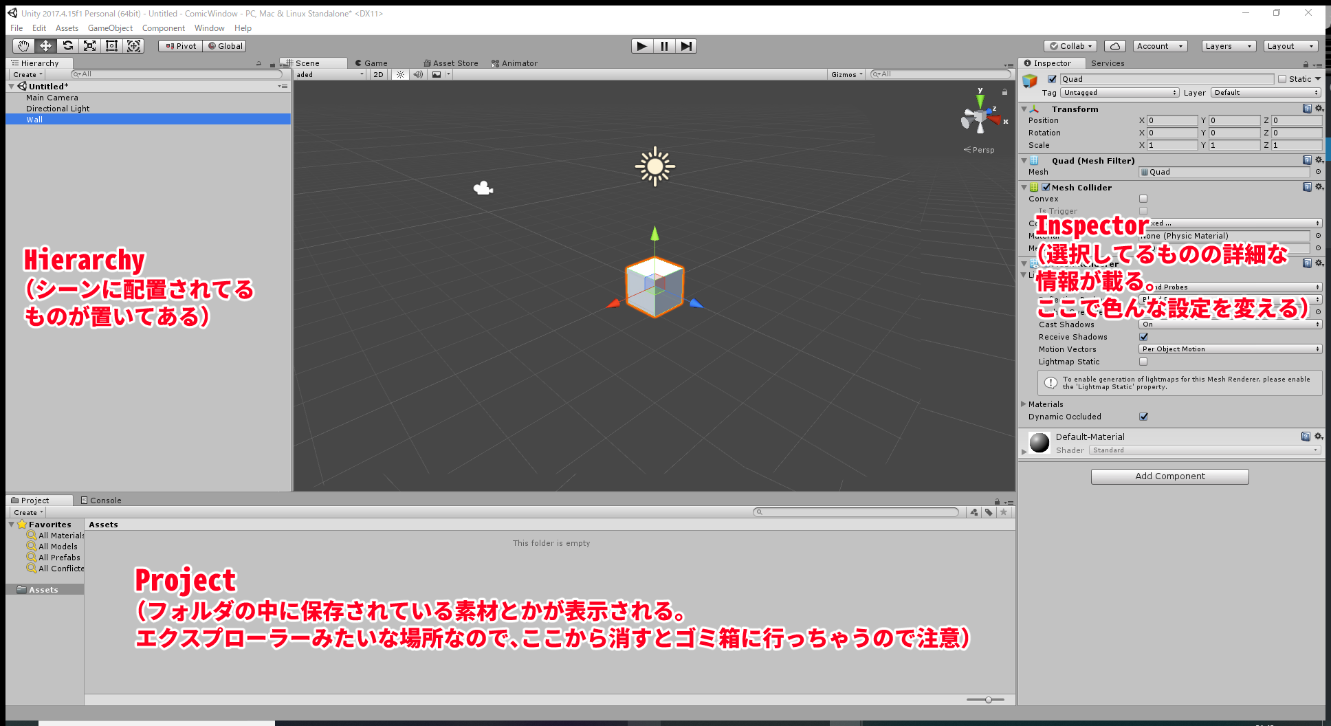
‘Hierarchy‘, ‘Project‘ and ‘Inspector‘ are the terms used frequently. Please remember them (I write them in italics in this article).
By selecting ‘Wall’ in the Hierarchy, various information is displayed in the Inspector.
In ‘Transform’ at the top, you can transform and move the object.
Now, set the parameters in the ‘Transform’ of the Wall as shown below.
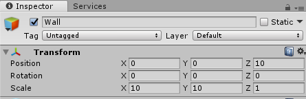

The base wall has been completed just by setting those parameters. Adjust the position of the camera for better visibility.
Next, create ‘Material‘ and ‘Shader‘ to apply to the Wall.
Those define how an object looks and we apply them to all the object we create from now.
Right-click on the Project window and select ‘Create > Folder’ to create a folder. Rename it ‘Wall’.
Move to that folder and select ‘Create > Material’ to create a Material. Rename it ‘Wall’.
Then, select ‘Create > Shader > Standard Surface Shader’ to create a Shader and rename it ‘Wall’.
Next, we rewrite the content of the Shader. However, if you open it, you will find that it’s written in a difficult language.
So, delete all the lines, copy and paste the following code anyway. You don’t need to understand the content itself.
Shader "Custom/Wall" {
	Properties {
		_Mask ("Mask", Int) = 100
		_Color ("Color", Color) = (1,1,1,1)
		_MainTex ("Albedo (RGB)", 2D) = "white" {}
		_Glossiness ("Smoothness", Range(0,1)) = 0.5
		_Metallic ("Metallic", Range(0,1)) = 0.0
	}
	SubShader {
		Tags
		{
			"RenderType"="Opaque"
			"Queue" = "Geometry-2"
		}
		LOD 200

		Stencil
		{
			Ref [_Mask]
			Comp NotEqual
		}

		CGPROGRAM
		// Physically based Standard lighting model, and enable shadows on all light types
		#pragma surface surf Standard fullforwardshadows

		// Use shader model 3.0 target, to get nicer looking lighting
		#pragma target 3.0

		sampler2D _MainTex;

		struct Input {
			float2 uv_MainTex;
		};

		half _Glossiness;
		half _Metallic;
		fixed4 _Color;

		// Add instancing support for this shader. You need to check 'Enable Instancing' on materials that use the shader.
		// See https://docs.unity3d.com/Manual/GPUInstancing.html for more information about instancing.
		// #pragma instancing_options assumeuniformscaling
		UNITY_INSTANCING_BUFFER_START(Props)
			// put more per-instance properties here
		UNITY_INSTANCING_BUFFER_END(Props)

		void surf (Input IN, inout SurfaceOutputStandard o) {
			// Albedo comes from a texture tinted by color
			fixed4 c = tex2D (_MainTex, IN.uv_MainTex) * _Color;
			o.Albedo = c.rgb;
			// Metallic and smoothness come from slider variables
			o.Metallic = _Metallic;
			o.Smoothness = _Glossiness;
			o.Alpha = c.a;
		}
		ENDCG
	}
	FallBack "Diffuse"
}
Now, we apply the created Material and Shader to the Wall in the Hierarchy.
Firstly, drag the ‘Wall’ Material into the Wall in the Hierarchy.
Click the Wall in the Hierarchy and you will find the ‘Wall’ Material at the bottom of the Inspector.
‘Shader’ has been set to ‘Standard’, so click it and select ‘Custom > Wall’.
Now, the ‘Wall’ Material and Shader have been applied.
Let’s change the colour of the wall, too.
Change the colour in the Shader setting as shown below.
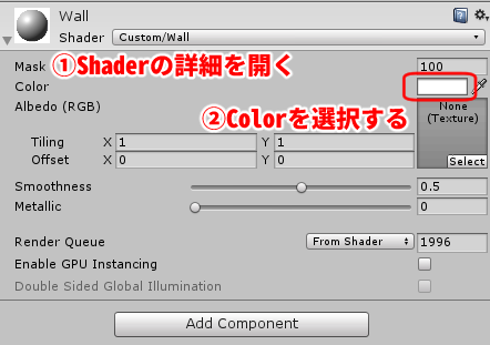
Select the Wall in the Hierarchy. In the Inspector, you can modify the Shader setting.
It completes the setting for the wall.
②Create a frame that makes ‘Wall’ transparent
Click on a blank place in the Hierarchy. With nothing selected, right-click and select ‘Create Empty’.
It creates a GameObject. Rename it ‘KOMA1’ and set the Position of ‘Transform’ to (0,0,0) in the Inspector.
Next, with ‘KOMA1’ selected, right-click and select ‘3D object > Quad’.
This Quad will be a frame, so add a ‘frame’ feature in advance.
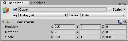
Click ‘KOMA1’ again and select ‘3D Object > Cube’. As shown below, set the parameters of ‘Transform’ at the top of the Inspector.
Next, in the Project window, right-click and select ‘Crate > Material’. Rename it ‘Frame’.
Drag and drop the Frame into the Cube in the Hierarchy.
With the Cube selected, set ‘Unit/Color’ for the Shader of ‘Frame’ displayed at the bottom of the Inspector.
As before, you can change the colour with ‘Main Color’. Select the black colour this time.
By the effect of the Shader, the Cube with the Material applied turns black as the Material is coloured in Black.
It creates one side of the frame, so duplicate(Ctrl+D) it to complete the four sides.
Rename the Cube ‘Frame’. With this Frame selected, duplicate it three times. In the Inspector, set ‘Transform’ of each side as shown below.
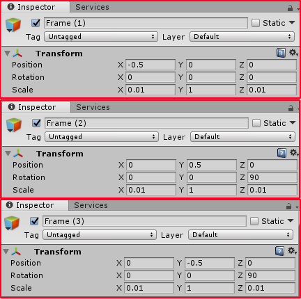
Now, we completed a frame.
Next, we are going to set up the Quad.
Firstly, rename the Quad ‘Wall_KOMA’.
In the Project view, create a Material and a Shader again in the ‘Wall’ folder. Rename both the Material and Shader to ‘Wall_KOMA’.
Copy and paste the following code in the ‘Wall_KOMA’ Shader.
Shader "Custom/Wall_KOMA"
{
	Properties
	{
		_Mask ("Mask", Int) = 100
	}

	SubShader
	{

		Tags
		{
			"RenderType" = "Opaque"
			"Queue" = "Geometry-3"
		}

		CGINCLUDE

		#include "UnityCG.cginc"

		struct v2f
		{
			float4 vertex : SV_POSITION;
			UNITY_VERTEX_OUTPUT_STEREO
		};

		v2f vert(appdata_base v)
		{
			v2f o;
			UNITY_SETUP_INSTANCE_ID(v);
			UNITY_INITIALIZE_VERTEX_OUTPUT_STEREO(o);
			o.vertex = UnityObjectToClipPos(v.vertex);
			return o;
		}

		fixed4 frag (v2f i) : SV_Target
		{
			return 0;
		}

		ENDCG

		Pass
		{
			ColorMask 0
			ZWrite Off
			Stencil
			{
				Ref [_Mask]
				Comp Always
				Pass Replace
			}

			CGPROGRAM
			#pragma vertex vert
			#pragma fragment frag
			ENDCG
		}

	}

}
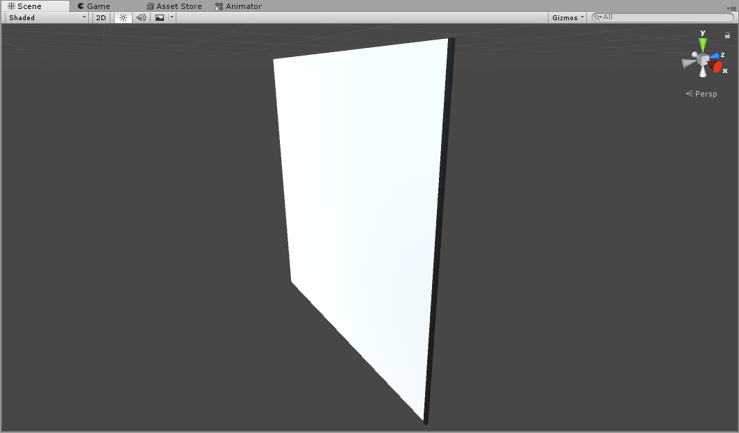
Drag and drop the created ‘Wall_KOMA’ Material into ‘Wall_KOMA’ in the Hierarchy. In the Inspector, set ‘Shader’ to ‘Wall_KOMA’.
Then, the white frame turns transparent. Now, you can see it make the wall transparent by adjusting the direction of the camera so that it points the wall.
The inside of the frame is transparent. The experiment was successful!
Next, let’s make ‘a cartoon-style wall’ appear on this transparent wall.
Complete the frame that you can see the cartoon world through
③Create a cartoon-style wall (ComicWall) displayed only through the frame
Duplicate the Wall and set it up so that it’s displayed only through the frame.
Having said that, you can do it in the same way as before, creating a Material and a Shader and applying them.
So, let it be done quickly.
Firstly, select the Wall in the Hierarchy and duplicate it (Ctrl+D). Rename it ‘ComicWall’.
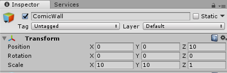
By making ‘Comic Wall’ identical shape as ‘Wall’, you can create an effect as if you saw a parallel world.
We will make assets in the Project, but it will get untidy if all the assets created are put in the same place. So, create the ‘ComicWall’ folder under ‘Assets’ to put them in.
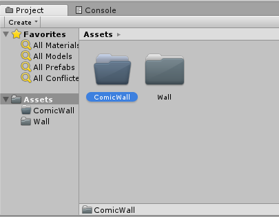
Tidying up the folder structure is a key for productivity.
Copy and paste the following code in the ‘ComicWall’ Shader.
Shader "Custom/ComicWall" {
	Properties
	{
		_Mask ("Mask", Int) = 100
		_MainTex ("Texture", 2D) = "white" {}
	}
	SubShader
	{
		Tags
		{
			"RenderType"="Opaque"
			"Queue" = "Geometry-2"
		}
		LOD 100

		Stencil
		{
			Ref [_Mask]
			Comp Equal
		}

		Pass
		{
			CGPROGRAM
			#pragma vertex vert
			#pragma fragment frag
			// make fog work
			#pragma multi_compile_fog

			#include "UnityCG.cginc"

			struct appdata
			{
				float4 vertex : POSITION;
				float2 uv : TEXCOORD0;
			};

			struct v2f
			{
				float2 uv : TEXCOORD0;
				UNITY_FOG_COORDS(1)
				float4 vertex : SV_POSITION;
			};

			sampler2D _MainTex;
			float4 _MainTex_ST;

			v2f vert (appdata v)
			{
				v2f o;
				o.vertex = UnityObjectToClipPos(v.vertex);
				o.uv = TRANSFORM_TEX(v.uv, _MainTex);
				UNITY_TRANSFER_FOG(o,o.vertex);
				return o;
			}

			fixed4 frag (v2f i) : SV_Target
			{
				// sample the texture
				fixed4 col = tex2D(_MainTex, i.uv);
				// apply fog
				UNITY_APPLY_FOG(i.fogCoord, col);
				return col;
			}
			ENDCG
		}
	}
}
Apply the created Material and Shader to ‘ComicWall’ in the Hierarchy.
Then, the wall turns white when you see it through the frame.

It doesn’t look cartoon-style yet
Make the wall into ‘cartoon-style’
We use ‘Texture‘ to make the wall look like a cartoon here.
‘Texture’ is used to put a pattern on the object by using an image file.
I prepared a cartoon-style Texture, so save it to a place on your PC.
Drag and drop the saved image file into the Project view of Unity to add.

It’s a free material so help yourself.
Select ‘ComicWall’ in the Hierarchy and, in the Inspector, click the ‘CW’ Material to expand.
From the Project view, drag and drop the image file into the grey box described as ‘None (Texture)’.
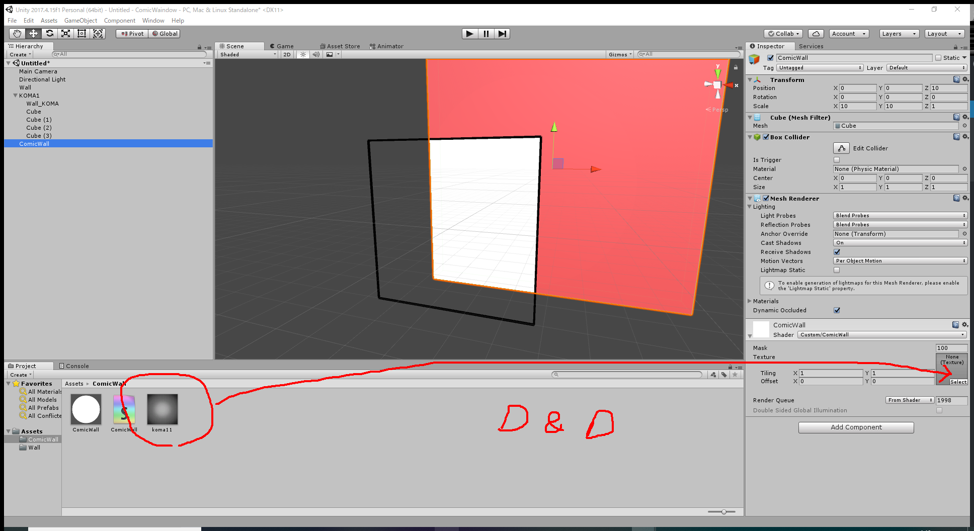
Then, the image file is applied to the background visible through the frame, so a cartoon world finally appears in the frame!
Next, let’s place a sphere (ComicObject1) in this cartoon world.
Create an object drawn only in the frame
④Create a frame to display a cartoon-style sphere (ComicObject1) on the frame created earlier (②)
Firstly, duplicate (Ctrl+D) ‘Wall_KOMA’ in the Hierarchy to create the second frame. Rename it ‘ComicObject_KOMA’.
Then, create the ‘ComicObject’ folder under ‘Assets’ in the Project view.
Create a Material and Shader in the ‘ComicObject’ folder and rename them ‘CO_KOMA1’ and ‘ComicObject_KOMA’ respectively.
Drag and drop them into ‘ComicObject_KOMA’ in the Hierarchy.
And, create a Standard Surface Shader in ‘ComicObject’ by selecting ‘Shader > Standard Surface Shader’ and rename it ‘ComicObject_KOMA’.
Copy and paste the following code into the Shader.
Shader "Custom/ComicObject_KOMA"
{
	Properties
	{
		_Mask ("Mask", Int) = 1
	}

	SubShader
	{

		Tags
		{
			"RenderType" = "Opaque"
		"Queue" = "Geometry-1"
		}

		CGINCLUDE

		#include "UnityCG.cginc"

		struct v2f
		{
			float4 vertex : SV_POSITION;
			UNITY_VERTEX_OUTPUT_STEREO
		};

		v2f vert(appdata_base v)
		{
			v2f o;
			UNITY_SETUP_INSTANCE_ID(v);
			UNITY_INITIALIZE_VERTEX_OUTPUT_STEREO(o);
			o.vertex = UnityObjectToClipPos(v.vertex);
			return o;
		}

		fixed4 frag (v2f i) : SV_Target
		{
			return 0;
		}

		ENDCG

		Pass
		{
			ColorMask 0
			ZWrite Off
			Stencil
			{
				Ref [_Mask]
				Comp Always
				Pass Replace
			}

			CGPROGRAM
			#pragma vertex vert
			#pragma fragment frag
			ENDCG
		}

	}

}
Drag and drop the ‘CO_KOMA1’ Material into ‘ComicObject_KOMA’. Set the Shader to ‘ComicObject_KOMA’.
It completes the frame for ‘ComicObject’.
⑤ Create ‘ComicObject1’ visible only in the frame
Click a blank place in the Hierarchy and, with nothing selected, create a Sphere. Then, rename it ‘ComicObject1’.
by the Inspector of ‘ComicObject1’, set (0,0,3) for the ‘Position (x,y,z)’ in the ‘Transform’ component, which places the Sphere in front of KOMA1.
Then, create a Material and Shader for ‘ComicObject’. Rename the Material to ‘CO1’ and the Shader to ‘ComicObject’.
Copy and paste the following code into the Shader.
Shader "Custom/ComicObject"
{
	Properties
	{
		_Mask ("Mask", Int) = 1
		_MainTex ("Texture", 2D) = "white" {}
	}
	SubShader
	{
		Tags { "RenderType"="Opaque" }
		LOD 100

		Stencil
		{
			Ref [_Mask]
			Comp Equal
		}

		Pass
		{
			CGPROGRAM
			#pragma vertex vert
			#pragma fragment frag
			// make fog work
			#pragma multi_compile_fog

			#include "UnityCG.cginc"

			struct appdata
			{
				float4 vertex : POSITION;
				float2 uv : TEXCOORD0;
			};

			struct v2f
			{
				float2 uv : TEXCOORD0;
				UNITY_FOG_COORDS(1)
				float4 vertex : SV_POSITION;
			};

			sampler2D _MainTex;
			float4 _MainTex_ST;

			v2f vert (appdata v)
			{
				v2f o;
				o.vertex = UnityObjectToClipPos(v.vertex);
				o.uv = TRANSFORM_TEX(v.uv, _MainTex);
				UNITY_TRANSFER_FOG(o,o.vertex);
				return o;
			}

			fixed4 frag (v2f i) : SV_Target
			{
				// sample the texture
				fixed4 col = tex2D(_MainTex, i.uv);
				// apply fog
				UNITY_APPLY_FOG(i.fogCoord, col);
				return col;
			}
			ENDCG
		}
	}
}
Again, apply the Material and the Shader to ‘ComicObject’.
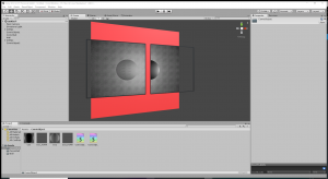
This is how the successful result looks. If anything went wrong, check if you applied the Shader correctly by using the Inspector.
Now, we completed all the settings for the first frame.
Now, let’s create another frame to finish up the project.
Create the second frame
⑥Duplicate the frame
⑦Create ComicObject2 visible only through the duplicated frame
Create another frame and make each frame show a different sphere.
Firstly, select and duplicate (Ctrl+D) ‘KOMA1’ in the Hierarchy. Rename it ‘KOMA2’.
In the current state, it’s overlapped with KOMA1, so set -1.1 for the X Position of KOMA2 by using the Inspector.
And, select and duplicate (Ctrl+D) ‘ComicObject1’ and rename it ‘ComicObject2’.
Again, it’s currently overlapped with ‘ComicObject1’, so set -1.1 for the X Position of ComicObject2 by using the Inspector.
Now there are two frames and two spheres but both of the frames show the same two spheres.
Next, in the Project view, duplicate the ‘CO1’ and ‘CO1_KOMA’ Material in the ComicObject folder and rename them ‘CO2’ and ‘CO2_KOMA’ respectively.
By using the Inspector, set ‘Mask’ to 2 for ‘CO2’ and ‘CO2_KOMA’.
This is important.
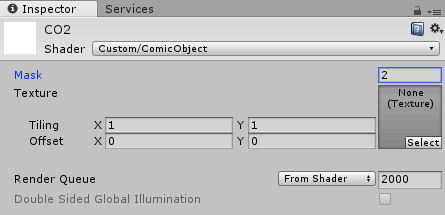
You can also use the Inspector on the Project view.
Apply the created ‘CO2’ Material to ‘ComicObject2’ in the Hierarchy and the ‘CO2_KOMA’ Material to ‘ComicObject_KOMA’ under KOMA2 in the Hierarchy.
The mechanism used here is that objects are drawn only when their Mask value corresponds with the Mask value of the frame.
When adding frames, you can create the same effect by adding the ‘CO’ and ‘CO_KOMA’ Materials and set the MASK value to 3, 4, 5…
As you can see in the Inspector of ‘Wall’ and ‘ComicWall’, their Mask values have been set to 100.
By applying separate Mask values to Walls and Objects, you can show a different Object in each frame, keeping the same wall shown.
(Otherwise, you need to duplicate the background for each frame. That is, you saved the number of objects by overlapping frames).
※By the way, if you placed only one frame (i.e. you don’t place multiple frames), both ‘WALL’ and ‘ComicWall’ can use the same MASK value as ‘ComicObject’.
In this case, you don’t need to make overlapped two frames. Choose an appropriate way for your application.
Finally, as a white sphere looks too plain, replace the texture of ComicObject with an appropriate one.
It’s completed now. Don’t forget to ‘Save Scene’ from the File Menu.
Congratulations!
By the way, the Shader of ‘ComicObject’ is based on ‘Unlit Shader’.
Further Note
I prepared the Shaders this time, but, in reality, you will face the situation where you want to use various Custom Shaders.
You don’t need to touch the Shaders for the frames (i.e. KOMAs). But, please add the lines to the codes of backgrounds and objects as follows.
【Wall】
◇In ‘Properties’, add _Mask (“Mask”, Int) = 100
◇In ‘SubShader/Tags’, add “Queue” = “Geometry-2“
◇Just before ‘CGPROGRAM’ (or Pass{CGPROGRAM), add Stencil {Ref [_Mask] Comp NotEqual}
【ComicWall】
◇In ‘Properties’, add _Mask (“Mask”, Int) = 100
◇in ‘SubShader/Tags’, add “Queue” = “Geometry-2“
◇Just before ‘CGPROGRAM’ (or Pass{CGPROGRAM), add Stencil{Ref [_Mask] Comp Equal}
【ComicObject】
◇In ‘Properties’, add _Mask (“Mask”, Int) = 1
◇Just before ‘CGPROGRAM’ (or Pass{CGPROGRAM), add Stencil{Ref [_Mask] Comp Equal}
If you have more than one ‘CGPROGRAM’, add ‘Stencil…’ for each CGPROGRAM.
By the way, it’s difficult to apply the ‘AlphaTest’ or ‘Transparent’ Shader to ‘Wall’ and “ComicWall’ (This is because ‘Wall’ and ‘ComicWall’ specify the ‘Queue’ value but ‘AlphaTest’ and ‘Transparent’ take the fixed Queue value).
In addition, they could have a compatibility issue with a Custom Shader that specifies the Queue value or overrides the ‘Stencil Buffer’ value.
In that case, you could make them work by adjusting the Queue value. Please try looking into it. Good luck!
It came to a long explanation, but now I’ve finished all explanations about how to ‘peep’ the cartoon world through the frame.
Although I used Textures to render a ‘cartoon world’ this time, I usually apply Shaders when creating a movie.
Search by ‘Manga Shader’ etc. If you found something you like, please try it with the setting shown earlier.
That’s all. Thank you for reading!
oeka_aki