In this article, we will introduce the basics of Global Illumination (GI) in Unity and how to use it to reflect indirect lighting-like expressions in a STYLY space.
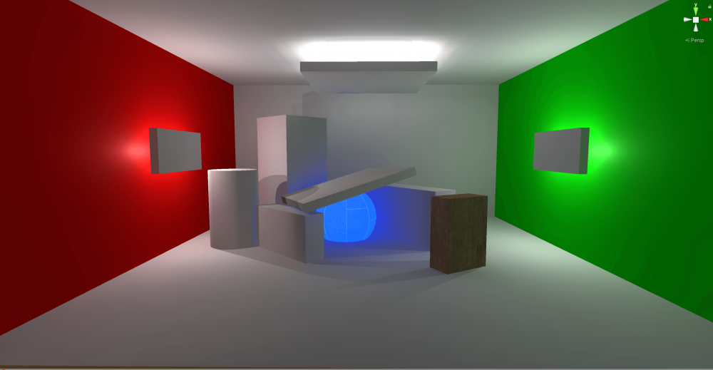
Finished image
Precautions
Unfortunately, the effects of the techniques described in this article will not be reflected correctly in web browsers (STYLY Studio and STYLY Gallery).
The effects will be reflected only in VR, so please take that into consideration when using the techniques.
Also, this time you need to upload the entire scene to STYLY.
The version of Unity used is 2019.3.6f1.
Click here to check which Unity versions are compatible with STYLY.
https://document.styly.cc/doc/docs/en-US/creator/creator_plugin_intro/#about-the-corresponding-unity-version
Sample
You can experience the sample scene created in this article from the following.
What is Global Illumination (GI)?
Global illumination (GI) is a technique for expressing light in CG in a way that is as natural as when humans see reality with their eyes.
In Japanese, it means “Global Illumination”, which means not only expressing localized direct light, but also expressing global lighting effects including indirect light such as reflected light and ambient light.
For more information on the basics of lights and how to use them in Unity, please refer to the following article.
Creating an Enclosed Room
To make the GI effect easier to understand, we will create a closed room with red and green walls based on the Cornell Box.
The Cornell Box is a famous model invented by Cornell University researchers to verify that CG lighting effects are rendered as realistically as possible.
Align MainCamera with Your Position in STYLY
Before we start creating the space, we will set the MainCamera to the same Your Position in STYLY, as we will be uploading the scene to STYLY.
I set the depth (Z coordinate) to -5 and the height (Y coordinate) to 1.5, as appropriate.
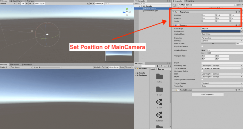
Set MainCamera’s Position to STYLY
Placing the Plane
Now let’s create the room.
This time, we will create the floor, walls, and roof all using the Unity basic object Plane.
The reason for this is that Planes do not have a mesh on the back side, so it is easy to make a closed space and see it from a perspective outside the walls in the Scene view.
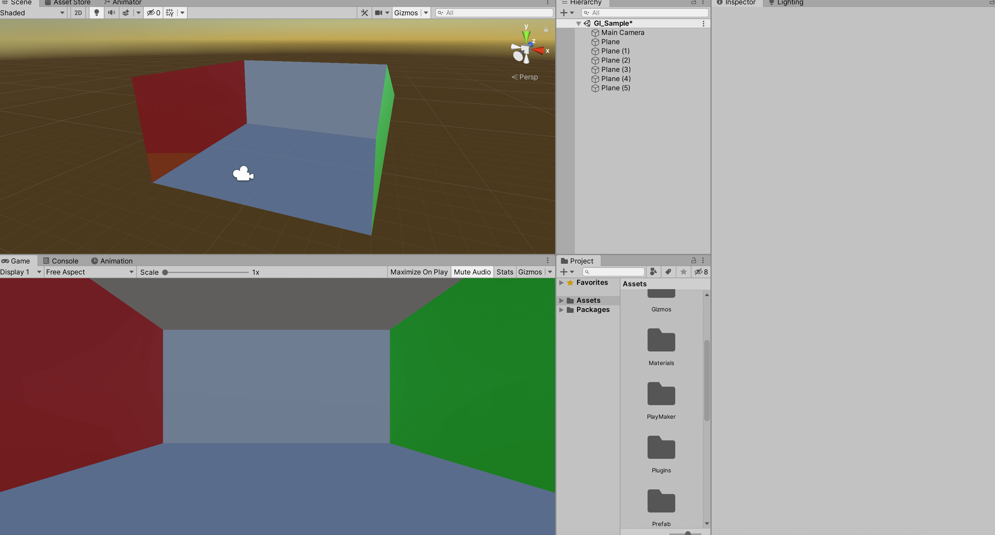
Place the Plane on six sides to create a room.
The Scale values for the walls and ceiling are all set to 1, and the height (Z coordinate in this case) of the walls is halved to 0.5.
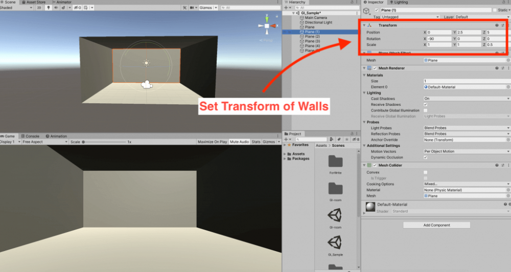
Creating a Room with Planes
In my case, the Transform for each Plane is as shown in the table below.
|
Plane(Floor) |
Position |
0 | 0 | 0 |
| Rotation | 0 | 0 | 0 | |
| Scale | 1 | 1 | 1 | |
| Plane (1) | Position | 0 | 2.5 | 5 |
| Rotation | -90 | 0 | 0 | |
| Scale | 1 | 1 | 0.5 | |
| Plane (2) | Position | -5 | 2.5 | 0 |
| Rotation | -90 | 0 | -90 | |
| Scale | 1 | 1 | 0.5 | |
| Plane (3) | Position | 5 | 2.5 | 0 |
| Rotation | -90 | 0 | 90 | |
| Scale | 1 | 1 | 0.5 | |
| Plane (4) | Position | 0 | 2.5 | -5 |
| Rotation | -90 | 0 | 180 | |
| Scale | 1 | 1 | 0.5 | |
| Plane (5)(Ceiling) | Position | 0 | 5 | 0 |
| Rotation | 180 | 0 | 0 | |
| Scale | 1 | 1 | 1 |
Adding color to the walls
The first step in creating and applying a material to the walls is to “Generate Lighting” from the Lighting window to make it easier to see the differences in color.
The Lighting window can be opened by selecting Window > Rendering > Lighting Settings from the File menu.
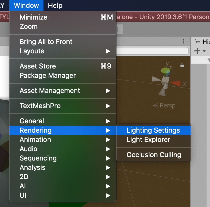
Press the “Generate Lighting” button at the bottom of the Lighting window.
If the button is grayed out and you can’t press it, uncheck the “Auto Generate” box next to it so that you can press it.
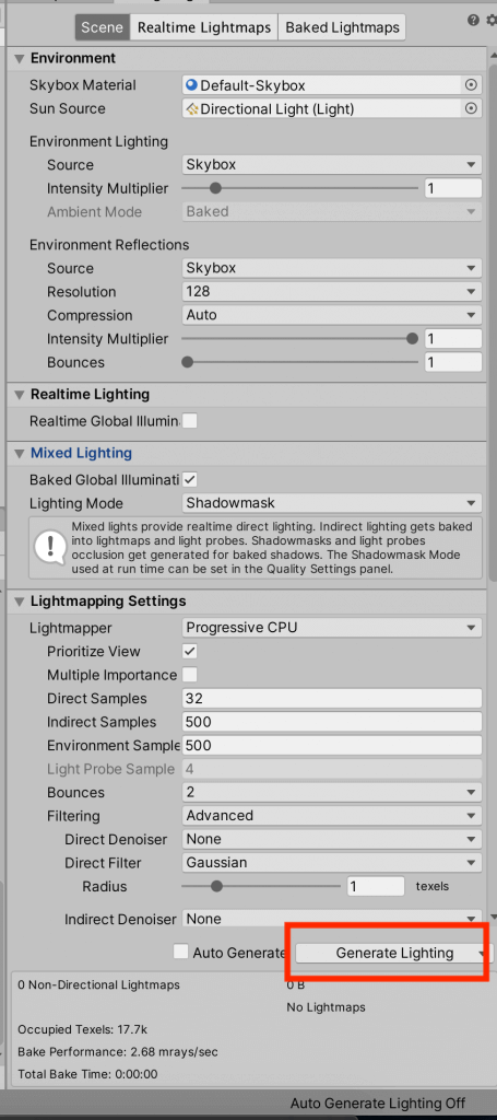
Select Generate Lighting
We will use the Lighting window often, so let’s lay it out to the right of the Inspector.
Now, let’s create the materials.
In the Project view, select Material from the Create menu and name it “Red”.
We will use the Standard Shader and set the Albedo color to (R:240, G:0, B:0).
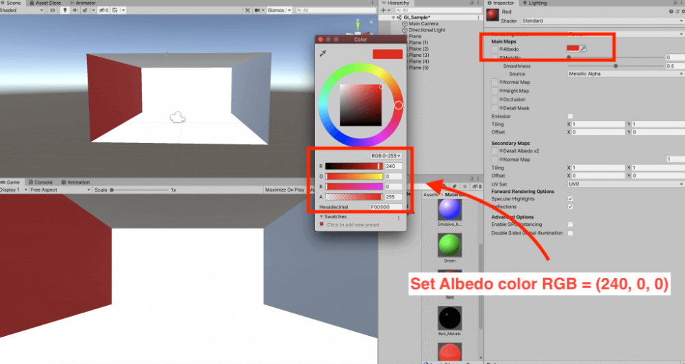
Create a material called “Green” and set the Albedo color to (R:0, G:240, B:0).
Apply these to each of the left and right walls. (Drag and drop the material from the Project view onto the GameObject you want to apply it to in the Hierarchy view.
For the other walls, floors and ceilings, we want them to be white, but not completely white (R:240, G:240, B:240), so we created a material called “White”.
After applying the material to all the planes, the result is as follows.
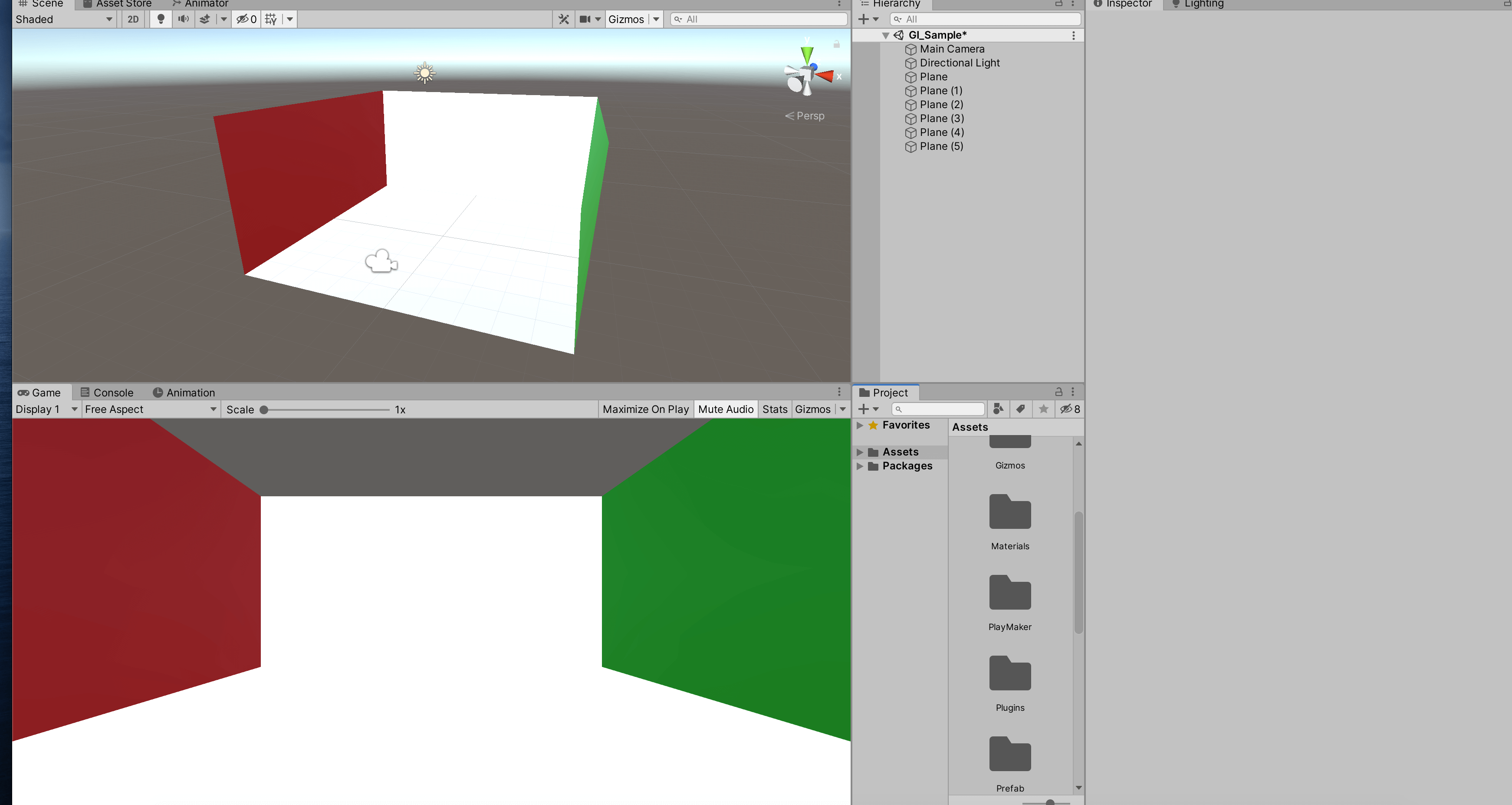
Creating a Cornell Box style room
The RGB value of “240” is a reference to the material chart provided by Unity.
This means that it is necessary to make the GI effect look more natural.
Save the scene. The name of the scene can be anything you want, but in this case we have chosen “GI_Sample”.
Since the room is still bright thanks to the Directional Light, let’s remove the Directional Light.
After removing the Directional Light
When we remove the Directional Light, the room is not completely dark.
This is actually because the GI effect is already enabled and the room is already illuminated.
So where are the settings for this lighting?
Setting up preferences for Lighting
This is where we will use the Lighting window we saw earlier.
The lighting settings for a scene in Unity are somewhat organized in the Lighting window.
If you look at the Lighting window, you will see “Scene” selected at the top of the window, which looks like a tab. (There are also “Realtime Lightmaps” and “Baked Lightmaps” in the list.
Then the room is completely dark.
- Environment > Environment Lighting > Intensity Multiplier
- Environment > Environment Reflections > Intensity Multiplier
The room is now completely dark.
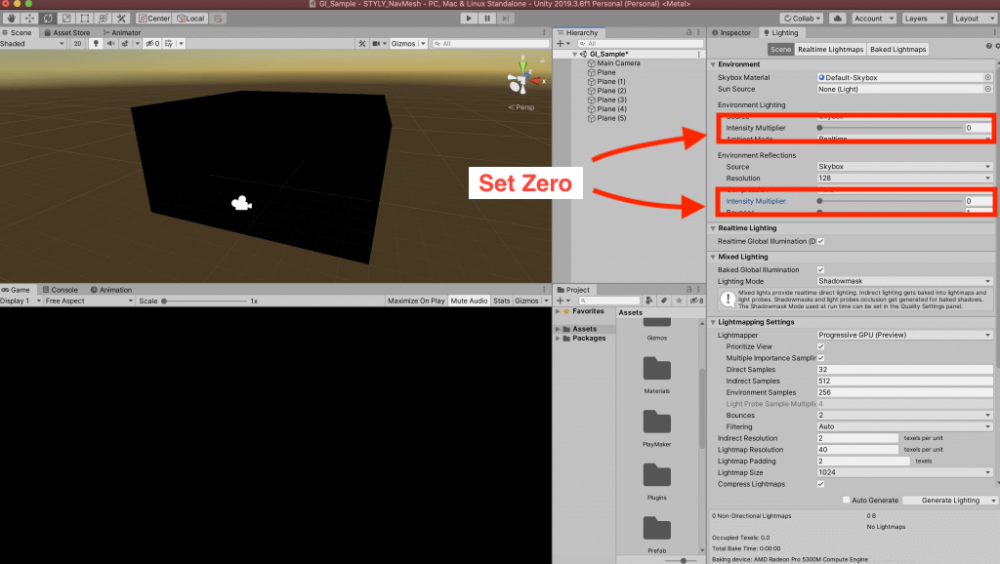
The room is now completely dark
Environment Lighting and Environment Reflections are both settings related to ambient light, and Intensity Multiplier allows you to set the degree of brightness.
The Intensity Multiplier allows you to set the degree of brightness. The default setting is 1, which means that even if the room is closed, it will be illuminated by ambient light, and even if there is no light in the scene, it will be bright.
There is also a Source item for each, and by default both are set to “Skybox”.
This means that the source of the ambient light calculation is set to Skybox.
Since it is difficult to work in total darkness, let’s return the Intensity Multiplier to its original value of 1.
Place a glowing object
We will use an Emissive object as the light source.
First, we will place the Cube and create and apply a material named “Emissive”.
To make it an Emissive object, simply enable Emission on the material and set the Emission > Color > Intensity value to 0 or higher. I set it to 1 for now.
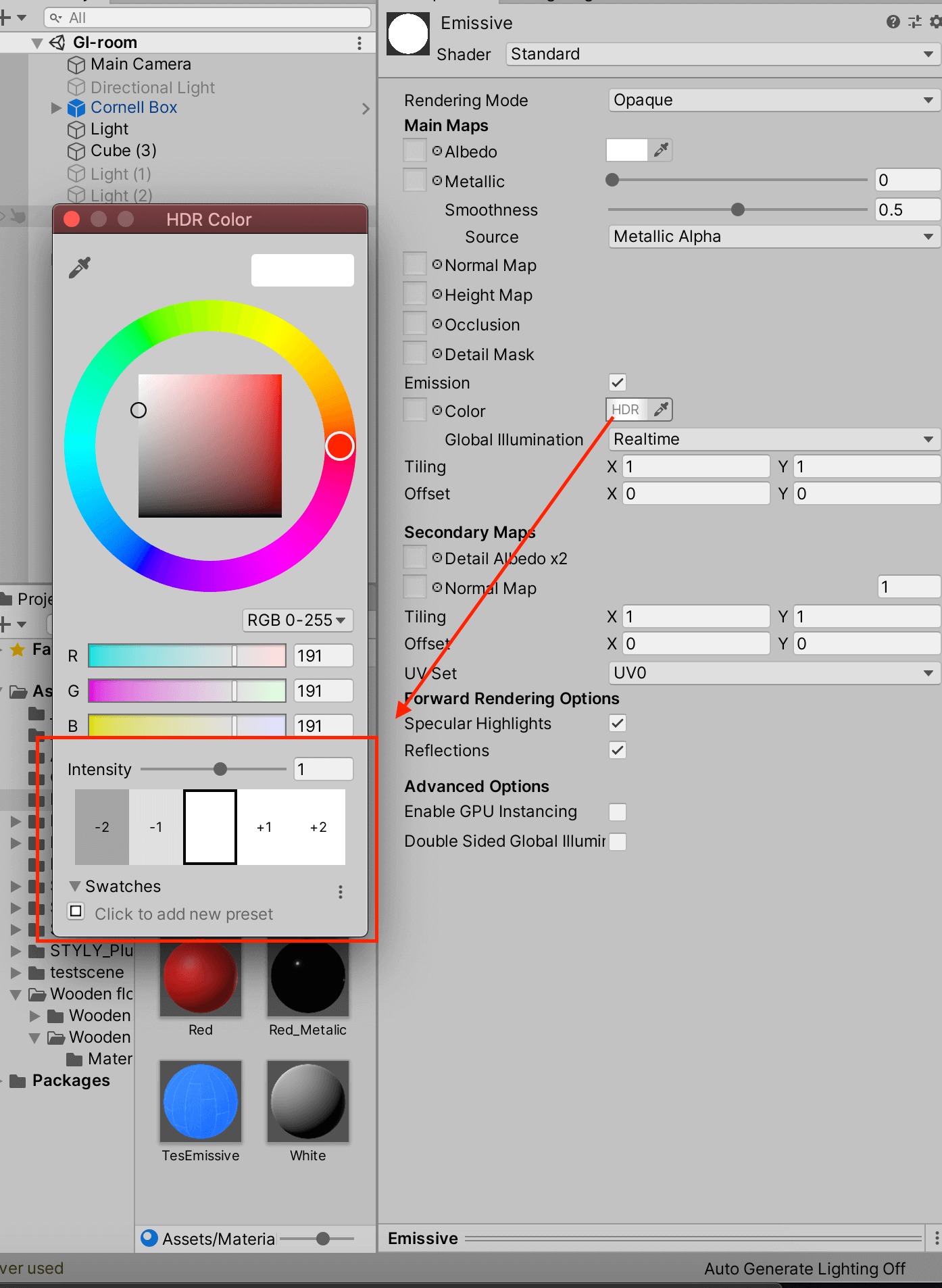
Emissive object properties
The object with the material with Emission turned on.
The only thing is that the light will not affect the surrounding objects.
To affect them, we need to turn on the Contribute Global Illumination checkbox on the Cube itself and on the GameObjects we want to affect (in this case, the surrounding planes).
Go to Mesh Renderer > Lighting > Contribute Global Illumination and turn on the checkbox.
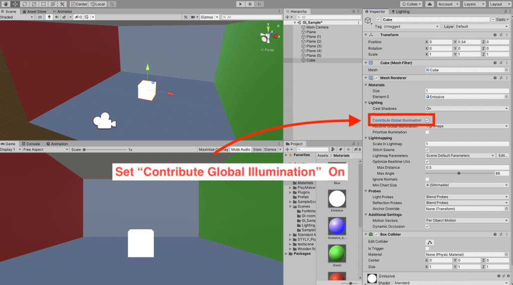
Turn on Contribute Global Illumination
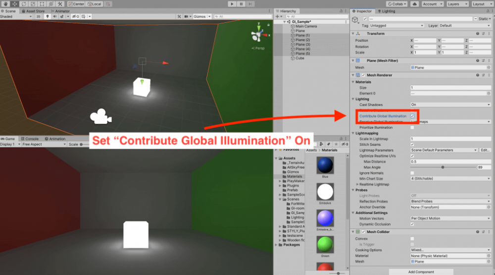
Turn on Contribute Global Illumination for the Plane
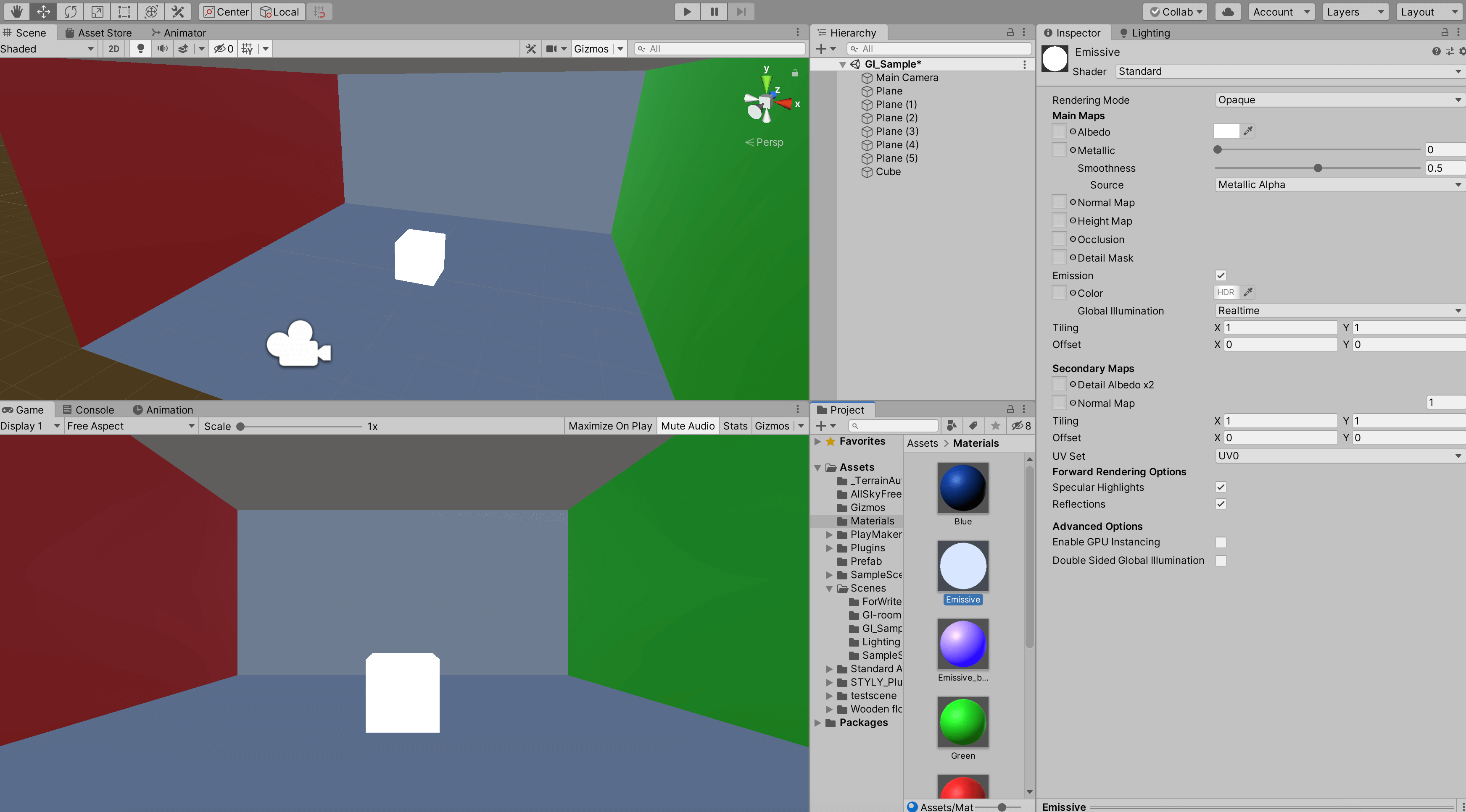
Now that it looks like it is emitting light, we thin it down and place it on the ceiling.
As you move the cube and turn Contribute Global Illumination on and off, a progress meter will appear in the lower right corner of the screen, indicating that the lighting effect is being applied after some processing is done.
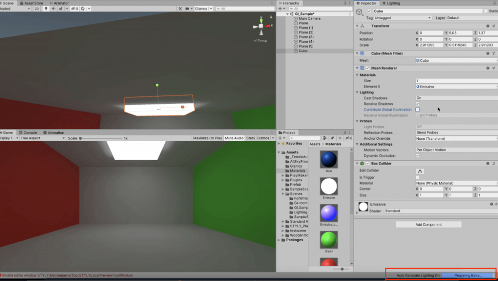
The lighting process in progress
(By the way, the Emissive object is not exactly a Light, but it has the same GI effect as the Light, and unlike the Light, the Emissive object itself emits light, which is useful for creating fluorescent or neon lights.)
Manually performing the lighting pre-calculation
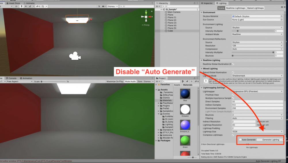
Now let’s go back to the Lighting window.
At the bottom, the item “Auto Generate” is checked.
If you turn it off, the button “Generate Lighting” is now enabled.
If you move the Emissive Cube or turn on/off the Contibute Global Illumination, the lighting in the scene will not change.
Instead, when you press the “Generate Lighting” button, the process is executed and the lighting is changed according to what you have edited.
Also, after this process was executed, a folder with the name of the scene being set and two files were created in the Project view.
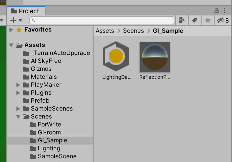
Lighting data has been created
This process is called lighting pre-calculation, and the pre-calculated data associated with the scene will be created in a folder with the same name as the scene.
This data will be used for drawing when Unity or STYLY is run.
Also, uncheck Mixed Lighting >Baked Global Illumination in the Lighting window.
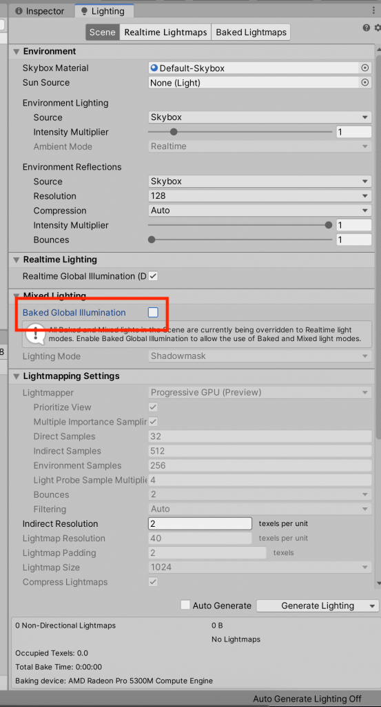
Then press the Generate Lighting button to pre-calculate the lighting. (Hereinafter simply referred to as “Generate Lighting.”)
If the light doesn’t seem to be generated properly, change the Emissive material’s Emission > Global Illumination to Realtime.
If the light does not generate properly, change the Emissive material’s Emission > Global Illumination to Realtime, and since you disabled Auto Generate, you will need to Generate every time you want to make a lighting-related change to your scene.
The reason why we chose to manually generate is to make it easier to see which changes affect the lighting effect.
I won’t go into detail about Baked Global Illumination, but I turned it off to make sure it would be reflected when uploading to STYLY.
Place the primitives in the room
As it is, the fluorescent lamp-like object is bare and cannot be used for indirect lighting, so we will create a lampshade-like object with a Cube and place it under the Emissive object.
We will also change the Intensity of the Emissive material to 2.5 to brighten up the scene.
Then, place the Cube and other primitives on the floor as desired.
For the primitives I added, I of course turned on the Contribute Global Illumination and applied the White material.
Also, set the Smoothness of the White material to 0. I also set the Smoothness of the White material to 0, in order to diffuse the light from the surface of the object better.
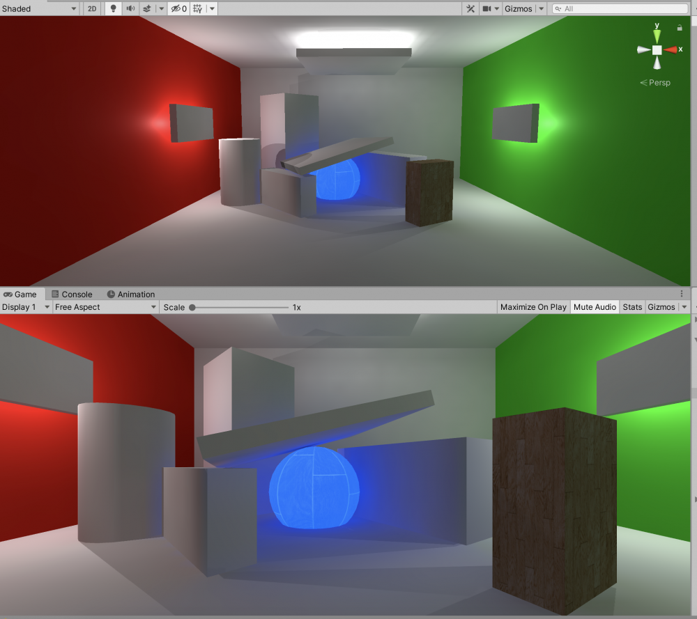
The result of the Generate Lighting is shown in the image below.
The surface of the primitive facing left is red, and the one on the right is green.
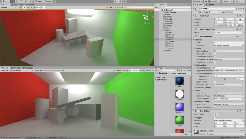
Scene with the primitives in place
This is because the light from the Emissive object is reflecting off the walls and reaching the surface of the primitives.
This is one of the effects of GI.
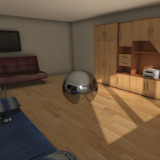
Of course, the same is true for textured materials.
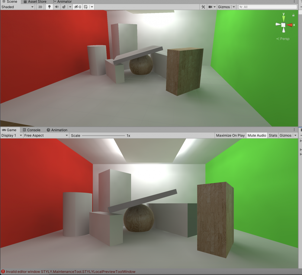
The textures also reflect the reflected light
I also placed Emissive objects on the red and green walls, and made the textured Sphere Emissive as well.
I wanted to make it a little darker, so I lowered all the Emission brightness values to 1.5.
I also set the two ambient light brightness values mentioned above to zero.
- Environment > Environment Lighting > Intensity Multiplier
- Environment > Environment Reflections > Intensity Multiplier
Add a model that emits light
Now it is nice and dark, but the light leaking from the indirect light (Emissive object) is fading.
In the Lighting window, change the Light Mapping Settings > Indirect Resolution from the default value of 2 to 4.
Indirect Resolution is the resolution of the indirect light.
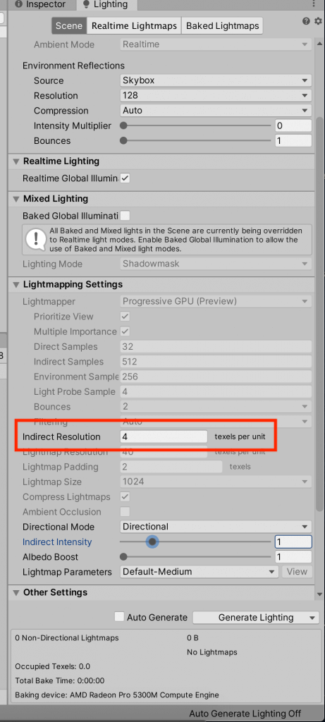
Lighting window
Then click Generate Lighting.
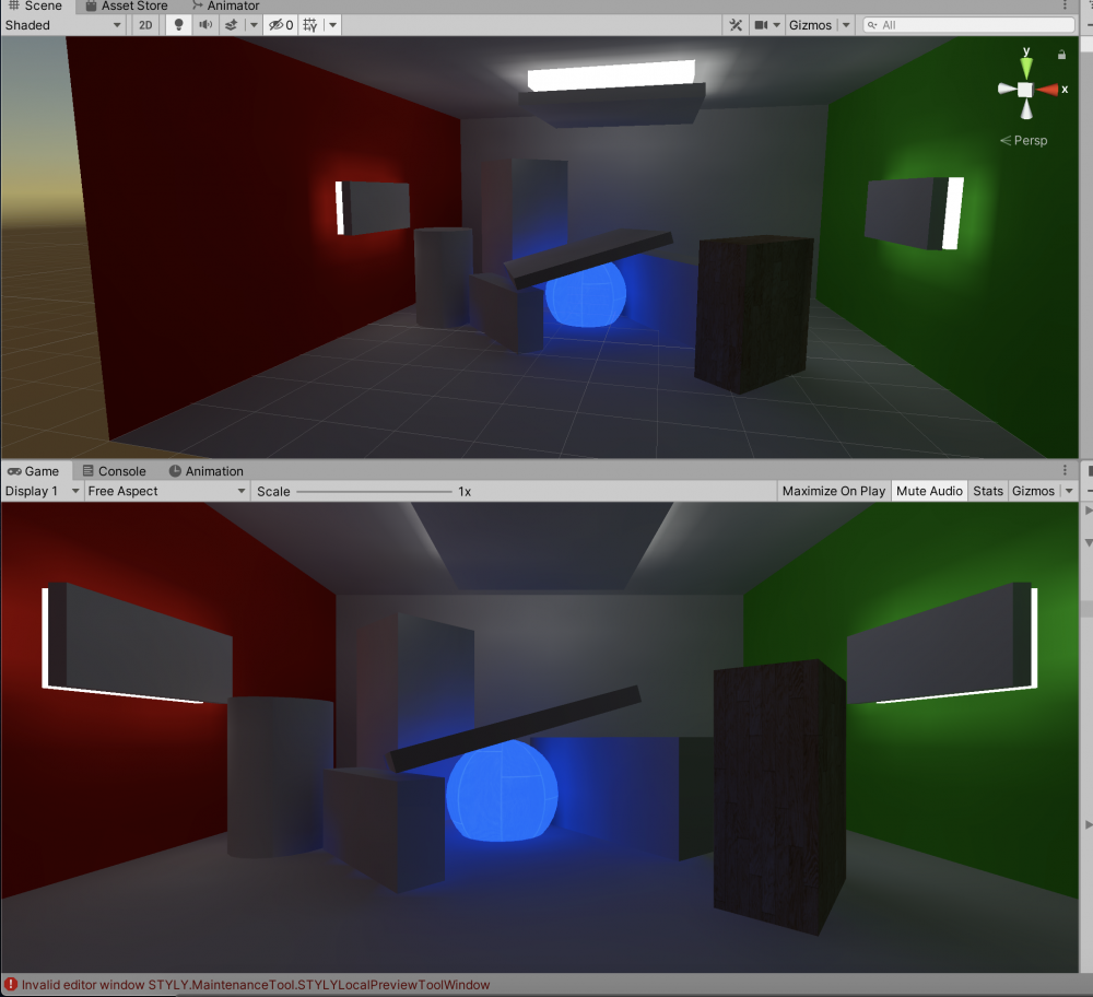
The light on the wall side of the Emissive object is now brighter.
Scene with the Indirect Resolution value changed
Since the whole scene is now too bright, we can adjust the brightness of the indirect light using Light Mapping Settings > Indirect Intensity.
In this case, we set it to 0.7.
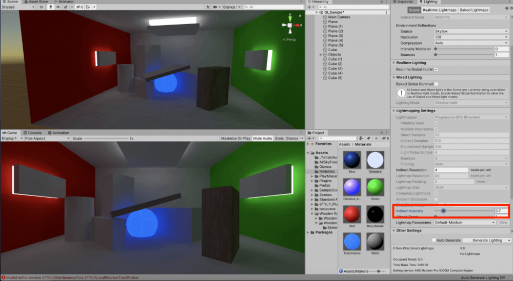
Lighting window
The brightness is good, but I was concerned that the resolution of the light hitting the wall was too coarse.
On the other hand, if you increase the Indirect Resolution too much, the Generate Lighting process will take a long time, making it less efficient.
It may also affect the performance at runtime, so I’ll change to Point Light for the wall.
Due to the specifications of STYLY, the “Render Mode” of Point Light must be set to “Important” for the light to function, so set it as such.
Also, to draw shadows from the Point Light, change the “Shadow Type” of the Point Light to “Hard Shadows”.
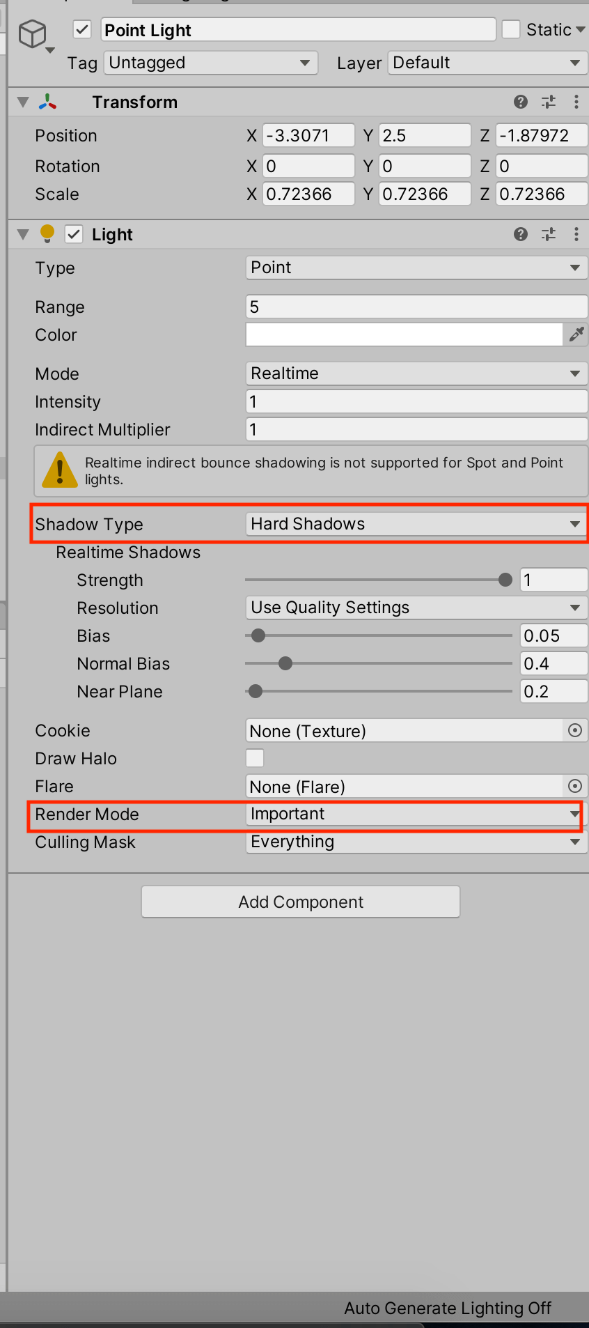
Point Light Settings
Let’s try Generate Lighting in this state.
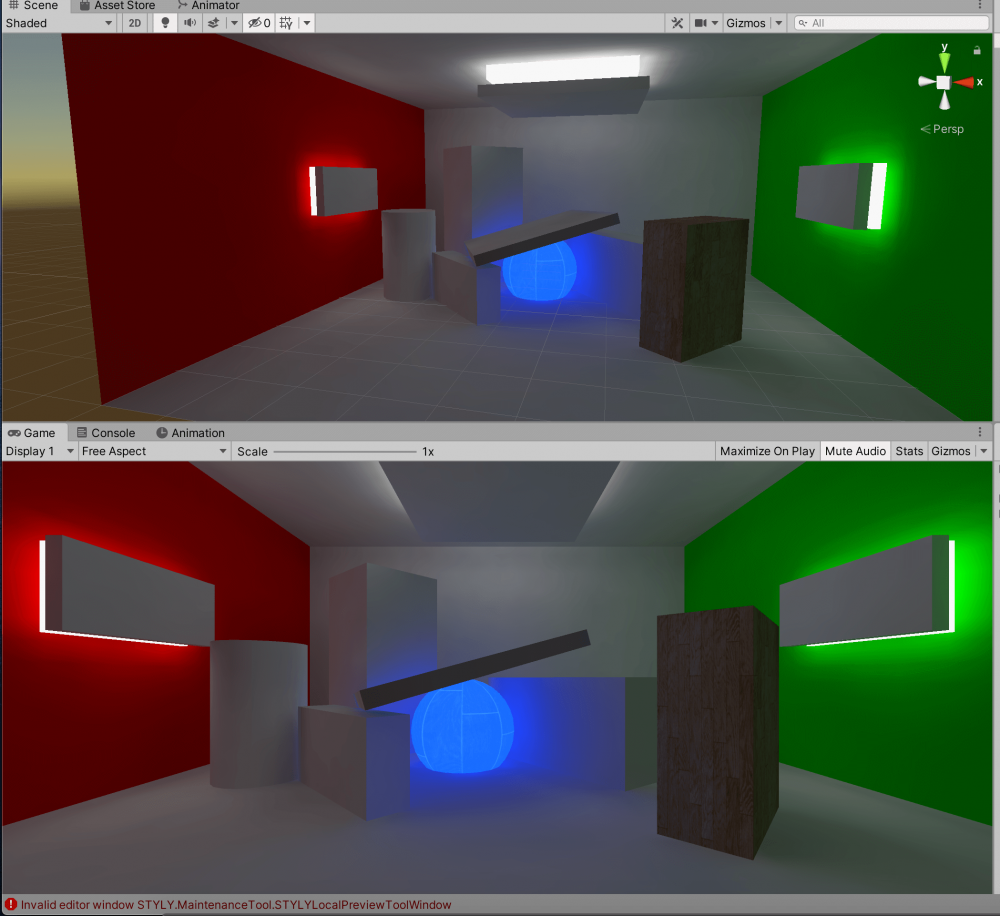
Change the light source near the wall to Point Light
Since Point Light is spherical, the shape of the light has changed, but the roughness has disappeared.
The shadows are also rendered properly.
Also, even if you change the Indirect Resolution back to 2, the roughness is no longer an issue.
Additional information
If you refer to the official Unity tutorial, it seems that Indirect Resolution of 4 is a very high value.
Even for indoor spaces where indirect light representation is more complex, 2-3 is about right.
Precomputed Realtime GI (Global Illumination)
*The name “Realtime Resolution” in this tutorial seems to have been changed to “Indirect Resolution”.
This time, I used the Precomputed Realtime GI above, and although it is precomputed by Generate Lighting, it calculates the light including indirect light at runtime (real time) based on it.
When using Precomputed Realtime GI, please note that the “Indirect Resolution” will affect the runtime performance.
Uploading to STYLY
Now, let’s upload the finished space to STYLY.
This time, we will upload the entire Unity scene.
See here for how to upload a Unity scene to STYLY.
The pre-calculated lighting data created by Generate Lighting will also be included in the upload.
After uploading, you should remove the Directional Light that is attached to the STYLY scene by default because it makes the scene too bright.
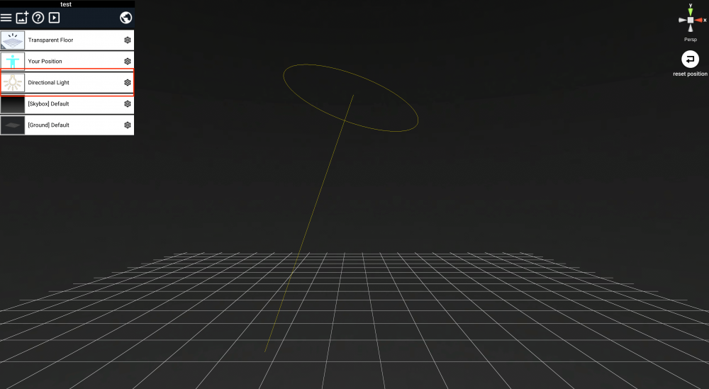
Remove Directional Light
If you view the scene in a web browser (STYLY Studio or STYLY Gallery), the light will not be reflected, but if you view it in the STYLY app with VR goggles on, the light will be reflected as you see it in Unity.
However, I felt that the light was brighter when viewed with VR goggles than it looked on the PC display.
This might be different depending on the VR goggles you use.
Summary
In this article, I tried to use Unity’s GI, Emission, and Point Light to create an indirect lighting effect.
There are many settings and things to learn about Unity’s lighting expression, and it’s too deep to introduce here, but I think you can create a more natural expression and comfortable space by being aware of GI and using it well.
In this article, I only used static spaces with non-moving objects, but in the future, I would like to write about moving objects and spaces where the light itself changes.
I would like to write about moving objects and spaces where the light itself changes.
Information used as a reference
The following articles were mainly used as references for this project.