In this article, I will show how to explode a 3D model into polygon pieces. The explosion is triggered by a set distance between the camera and the model.
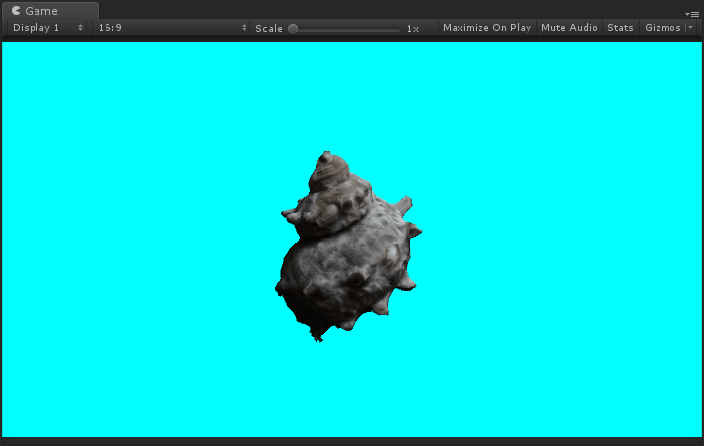
A turban shell with the ‘Polygon Destruction’ shader that explodes the 3D model when the camera approaches.
Change the Object According to the Distance from the Camera
You can add motion to the drawn object by changing the parameters of the shader.
This time I use the distance between the camera and the object as a variable.
Let’s create an effect that the object changes its color, etc. according to the camera’s movement.

The effect that changes the color when the camera approaches
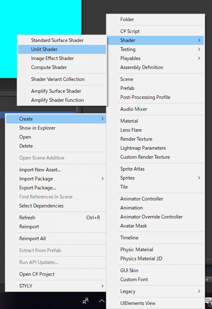
In the Project window, select ‘Create > Shader > Unlit Shader’ to create a new Shader file.
Name the Shader file ‘ColorGradient’
Modify the created Shader file as follows.
Shader "Custom/Color Gradient"
{
	Properties
	{
		_Dsitance ("Distance", float) = 3.0
		_FarColor ("Far Color", Color) = (0, 0, 0, 1)
		_NearColor ("Near Color", Color) = (1, 1, 1, 1)
	}
	SubShader
	{
		Tags { "RenderType"="Opaque" }

		Pass
		{
			CGPROGRAM
			#pragma vertex vert
			#pragma fragment frag

			#include "UnityCG.cginc"

			float _Dsitance;
			fixed4 _FarColor;
			fixed4 _NearColor;

			struct appdata
			{
				float4 vertex : POSITION;
			};

			struct v2f
			{
				float4 vertex : SV_POSITION;
				float3 worldPos : TEXCOORD0;
			};

			v2f vert (appdata v)
			{
				v2f o;
				o.vertex = UnityObjectToClipPos(v.vertex);
				o.worldPos = mul(unity_ObjectToWorld, v.vertex); // Convert Local coordinates into World coordinates
				return o;
			}

			fixed4 frag (v2f i) : SV_Target
			{
				// Get the distance between the camera and the object
				float dist = length(_WorldSpaceCameraPos - i.worldPos);
				// Change the colour by Lerp
				fixed4 col = fixed4(lerp(_NearColor.rgb, _FarColor.rgb, dist/_Dsitance), 1);
				return col;
			}
			ENDCG
		}
	}
}
This Shader converts the local coordinate system into the world coordinate system in the Vertex Shader and sends them to the Fragment Shader.
It will then calculate the distance between the camera and the object and changes the color of the object according to the calculated distance by using the Lerp function.
// Get the distance between the camera and the object

float dist = length(_WorldSpaceCameraPos - i.worldPos);

// Change the colour by Lerp

fixed4 col = fixed4(lerp(_NearColor.rgb, _FarColor.rgb, dist/_Dsitance), 1);
Now, the Shader changes the object according to the distance from the camera.
Add Motion to Individual Polygons
By using the Geometry Shader, you can add motion to individual polygons.
In the Shader, it’s processed in the following order.
- Vertex Shader
- Geometry Shader
- Fragment Shader
Note that the Geometry Shader doesn’t work on Web Player due to the limitation of WebGL.
When using it in STYLY, please be aware that it doesn’t work on ‘STYLY Studio’ but it works in VR.
Create a new Shader file as before, then modify the created Shader file as follows.
Shader "Custom/Simple Geometry"
{
	Properties
	{
		_Color ("Color", Color) = (1, 1, 1, 1)
	}
	SubShader
	{
		Tags { "RenderType"="Opaque" }

		Pass
		{
			CGPROGRAM
			#pragma vertex vert
			#pragma geometry geom
			#pragma fragment frag

			#include "UnityCG.cginc"

			fixed4 _Color;

			struct appdata
			{
				float4 vertex : POSITION;
				float2 uv : TEXCOORD0;
			};

			struct g2f
			{
				float4 vertex : SV_POSITION;
				float2 uv : TEXCOORD0;
			};

			appdata vert (appdata v)
			{
				return v;
			}

			// Geometry Shader
			[maxvertexcount(3)]
			void geom (triangle appdata input[3], inout TriangleStream<g2f> stream)
			{
				[unroll]
				for(int i = 0; i < 3; i++)
				{
					appdata v = input[i];
					g2f o;
					o.vertex = UnityObjectToClipPos(v.vertex);
					o.uv = v.uv;
					stream.Append(o);
				}
				stream.RestartStrip();
			}

			fixed4 frag (g2f i) : SV_Target
			{
				fixed4 col = _Color;
				return col;
			}
			ENDCG
		}
	}
	FallBack "Unlit/Color"
}
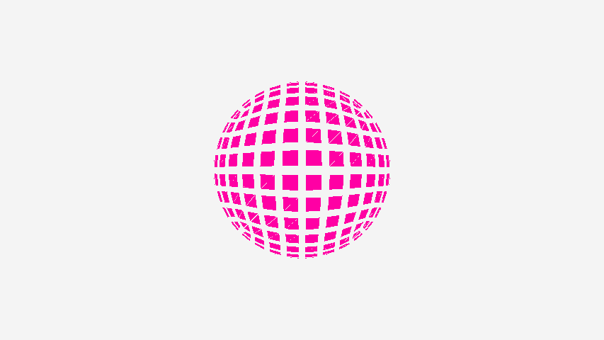
This Shader doesn’t add any motions. It’s just a sample to show how to write a code for the Geometry Shader.
The Geometry Shader that doesn’t change anything
Let’s add motion by using the ‘_SinTime’ Shader and the Geometry Shader.
The Geometry Shader that divides by normal vectors into polygons
Shader "Custom/Polygon Moving"
{
	Properties
	{
		_Color ("Color", Color) = (1, 1, 1, 1)
		_ScaleFactor ("Scale Factor", float) = 0.5
	}
	SubShader
	{
		Tags { "RenderType"="Opaque" }

		Pass
		{
			CGPROGRAM
			#pragma vertex vert
			#pragma geometry geom
			#pragma fragment frag

			#include "UnityCG.cginc"

			fixed4 _Color;
			float _ScaleFactor;

			struct appdata
			{
				float4 vertex : POSITION;
				float2 uv : TEXCOORD0;
			};

			struct g2f
			{
				float4 vertex : SV_POSITION;
				float2 uv : TEXCOORD0;
			};

			appdata vert (appdata v)
			{
				return v;
			}

			// Geometry Shader
			[maxvertexcount(3)]
			void geom (triangle appdata input[3], inout TriangleStream<g2f> stream)
			{
				// Calculate Normal Vector
				float3 vec1 = input[1].vertex - input[0].vertex;
				float3 vec2 = input[2].vertex - input[0].vertex;
				float3 normal = normalize(cross(vec1, vec2));

				[unroll]
				for(int i = 0; i < 3; i++)
				{
					appdata v = input[i];
					g2f o;
					// Move vertex along normal vector
					v.vertex.xyz += normal * (_SinTime.w * 0.5 + 0.5) * _ScaleFactor;
					o.vertex = UnityObjectToClipPos(v.vertex);
					o.uv = v.uv;
					stream.Append(o);
				}
				stream.RestartStrip();
			}

			fixed4 frag (g2f i) : SV_Target
			{
				fixed4 col = _Color;
				return col;
			}
			ENDCG
		}
	}
	FallBack "Unlit/Color"
}
This adds ‘the calculation of the normal vector’ and ‘the process to move vertices by using _SinTime’ to the simple Geometry Shader created earlier.
Now, I will explain this process step by step.
Calculate the Normal Vector
We calculate the outer product to get the normal vector. The outer product gives a vector perpendicular to the given two vectors that are not parallel.
In other words, for a triangular polygon, it gives the normal vector of the polygon, that is, a vector perpendicular to the two vectors that connects a vertex to other vertices.
// Calculate the normal vector

float3 vec1 = input[1].vertex - input[0].vertex;

float3 vec2 = input[2].vertex - input[0].vertex;

float3 normal = normalize(cross(vec1, vec2));
Animation by Using ‘_SinTime’
Next, we set up the animation. We use ‘_SineTime’, which is the sine of time. It smoothly oscillates between -1.0 and 1.0 as time goes by.
This kind of preset variable in Unity (‘Built-in variables’) allows you to save calculation cost.
Unity – Manual: ShaderLab Built-in shader variables
This time, in order to keep the value positive, we normalize it so that it smoothly oscillates between 0.0 and 1.0.
The minimum value -1.0 multiplied by 0.5 gives -0.5, and add 0.5, you have 0.0. Apply the same calculation to the maximum value 1.0, you have 1.0 (i.e. it doesn’t change after all).
_SinTime.w * 0.5 + 0.5
You have made the variable, which was oscillating between -1.0 and 1.0, now oscillate between 0.0 and 1.0.
Finally, in order to add a motion that breaks up the object into individual polygons along the normal vectors, multiply the normal vector by the ‘_SinTime-controlled’ variable and then add it to the coordinates of each vertex.
// Move vertices along the normal vector

v.vertex.xyz += normal * (_SinTime.w * 0.5 + 0.5) * _ScaleFactor;
The Program Code for the ‘Polygon Destruction’ Shader
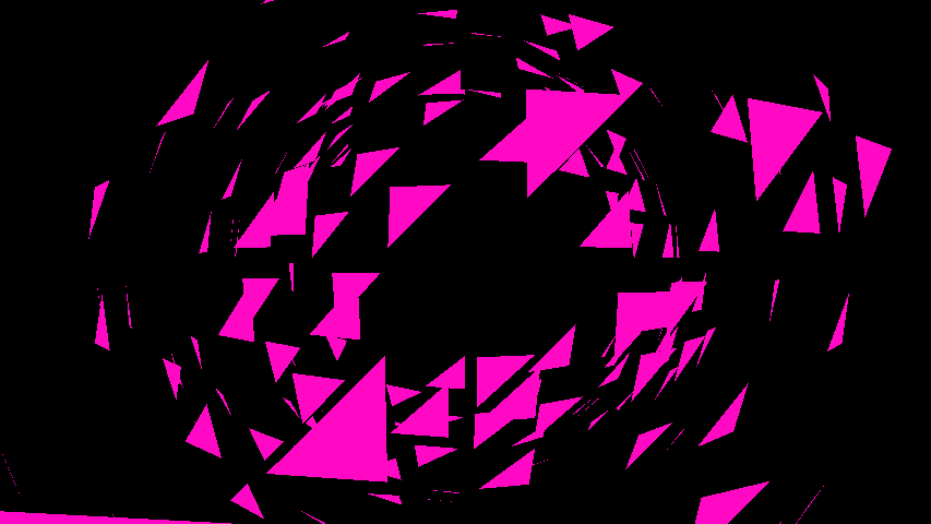
The ‘Polygon Destruction’ Shader that explodes the 3D model when the camera approaches
By combining ‘the distance between the camera and the object’ and ‘The geometry Shader’, creates the ‘Polygon Destruction’ Shader that explodes the 3D object when the camera approaches.
Create a Shader file and rewrite it as follows.
Shader "Custom/Polygon Destruction"
{
	Properties
	{
		_FarColor ("Far Color", Color) = (1, 1, 1, 1)
		_NearColor ("Near Color", Color) = (0, 0, 0, 1)
		_ScaleFactor ("Scale Factor", float) = 0.5
		_StartDistance ("Start Distance", float) = 3.0
	}
	SubShader
	{
		Tags { "RenderType"="Opaque" }

		Pass
		{
			CGPROGRAM
			#pragma vertex vert
			#pragma geometry geom
			#pragma fragment frag

			#include "UnityCG.cginc"

			fixed4 _FarColor;
			fixed4 _NearColor;
			fixed _ScaleFactor;
			fixed _StartDistance;

			struct appdata
			{
				float4 vertex : POSITION;
				float2 uv : TEXCOORD0;
			};

			struct g2f
			{
				float4 vertex : SV_POSITION;
				float2 uv : TEXCOORD0;
				fixed4 color : COLOR;
			};

			// Return random value
			float rand(float2 seed)
			{
				return frac(sin(dot(seed.xy, float2(12.9898, 78.233))) * 43758.5453);
			}

			appdata vert (appdata v)
			{
				return v;
			}

			// Geometry Shader
			[maxvertexcount(3)]
			void geom (triangle appdata input[3], inout TriangleStream<g2f> stream)
			{
				// The distance between the camera and the CoG of the polygon
				float3 center = (input[0].vertex + input[1].vertex + input[2].vertex) / 3;
				float4 worldPos = mul(unity_ObjectToWorld, float4(center, 1.0));
				float3 dist = length(_WorldSpaceCameraPos - worldPos);

				// Calculate the normal vector
				float3 vec1 = input[1].vertex - input[0].vertex;
				float3 vec2 = input[2].vertex - input[0].vertex;
				float3 normal = normalize(cross(vec1, vec2));

				// Change how the polygons explode according to the distance to the camera
				fixed destruction = clamp(_StartDistance - dist, 0.0, 1.0);
				// Change the colour according to the distance to the camera
				fixed gradient = clamp(dist - _StartDistance, 0.0, 1.0);

				fixed random = rand(center.xy);
				fixed3 random3 = random.xxx;

				[unroll]
				for(int i = 0; i < 3; i++)
				{
					appdata v = input[i];
					g2f o;
					// Move the vertex along the normal vector
					v.vertex.xyz += normal * destruction * _ScaleFactor * random3;
					o.vertex = UnityObjectToClipPos(v.vertex);
					o.uv = v.uv;
					// Change the colour by Lerp
					o.color = fixed4(lerp(_NearColor.rgb, _FarColor.rgb, gradient), 1);
					stream.Append(o);
				}
				stream.RestartStrip();
			}

			fixed4 frag (g2f i) : SV_Target
			{
				fixed4 col = i.color;
				return col;
			}
			ENDCG
		}
	}
	FallBack "Unlit/Color"
}
The processes in this Shader code are the combination of ‘The distance to the camera’ and ‘Processing individual polygons’ explained earlier.
The Effect of Using the ‘Polygon Destruction’ Shader
This time I added a motion that breaks up the object into individual polygons by the shader code referring to the distance from the camera. However, you can also create a motion by changing the parameters with ‘_SinTime’ or ‘Animator’.

The effect by using the Geometry Shader – 01

The effect by using the Geometry Shader – 02
When controlling by Animator, you can animate the object with varying motions.
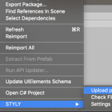
Upload to STYLY
Attach the Material created by your custom Shader to an object and upload it, Use this custom Shader in a STYLY Scene.
The following article explains more about how to upload an asset to STYLY:
The program coding may seem complicated at first, but if you can understand the different basic elements it will be simple to create your custom shaders. So, try to identify what is the ‘key’ element, once you do, you will make good use of shaders.