I explain how to render ‘scanline’, which looks like laser running on a surface, with Unity’s shader as shown below.
Scanline in VR space
Samples
The sample available in GitHub:
The sample VR space
How to make scanline in VR space
I explain how to create a scanline in VR space.
Use the x coordinate as colour
Unity’s shader takes the coordinate, where the pixel of the object on the screen is located, as a parameter. For example, if you used the x coordinate as the colour of the object, it would look like the shown below.
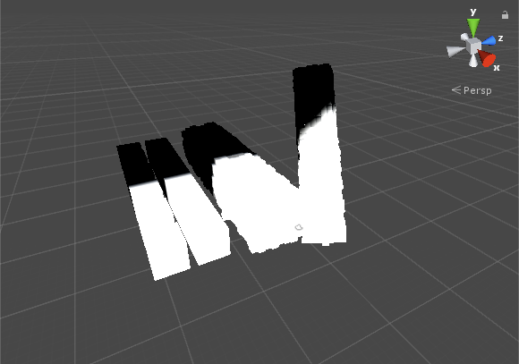
Use the x coordinate as the colour of an object
The part where the X coordinate is smaller than 0.0 is coloured in black, where it is larger than 1.0 is coloured in white, and it’s coloured in grey in the case the X coordinate takes the value between 0.0 and 1.0. The code for Unity’s ShaderLab is shown below.
float x = IN.worldPos.x; // x coordinate
o.Emission = x; // Use x as colour
Create scanline
When the condition, 0.0 ≦ the X coordinate ≦ 0.1, is satisfied, colour the object white. Otherwise, colour it black.
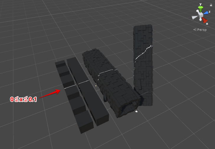
The part with the condition, 0≦x≦0.1, is coloured white.
The code for Unity’s ShaderLab is shown below.
float x = IN.worldPos.x; // x coordinate
o.Emission = step(0.0, x) * step(x, 0.1);  // Use x as colour
Add the trace effect
Add a trace to the scanline.
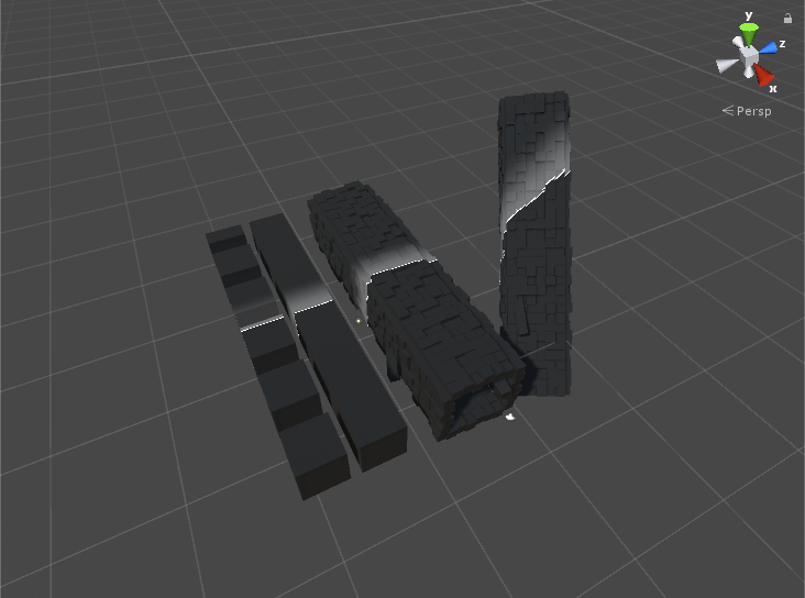
Add a trace to the scanline.
The code for Unity’s ShaderLab is shown below.
float x = IN.worldPos.x; // x coodinate
float scanline = step(0.0, x) * step(x, 0.1); // scanline
float trajectory = step(x, 0.0) * smoothstep(-4.0, 0.0, x); // trace of scanline
o.Emission = scanline + trajectory * 0.3; // output line and trace
Create animation
Move Scanline
Create a series of scanlines and animate them.
Animate scanlines
The code for Unity’s ShaderLab is shown below.
float x = IN.worldPos.x; // x coordinate
x -= _Time.z * 6.0; // subtract time from x coodinate
x = fmod(x, 12.0); // generate the float between 0.0 and 12.0
float scanline = step(-0.1, x) * step(x, 0.0); // scanline
float trajectory = step(x, 0.0) * smoothstep(-4.0, 0.0, x); // trace of scanline
o.Emission = scanline + trajectory * 0.3; // output as colour
Colour the scanlines ~ completion
Finally, colour the scanlines. Now we finished rendering the scanlines in VR space.
Colour the scanlines
float x = IN.worldPos.x; // x coordinate
x -= _Time.z * 6.0; // subtract time from x coodinate
x = fmod(x, 12.0); // generate the float between 0.0 and 12.0
float scanline = step(-0.1, x) * step(x, 0.0); // scanline
float trajectory = step(x, 0.0) * smoothstep(-4.0, 0.0, x); // trace of scanline
o.Emission = scanline * _LineColor + trajectory * _TrajectoryColor; // output as colour
Create Scanline with Unity
Create a shader file
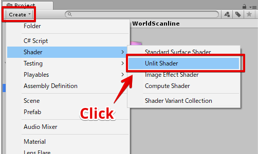
Select ‘Create > Shader > Unlit Shader’ to create a shader file.
Create a shader file
Name the shader file ‘WorldScanline’.
The shader file created.
Edit the shader file
Open the ‘WorldScanline’ shader, edit it as shown below.
Shader "STYLY/Examples/WorldScanline" {
	Properties{
		_MainTex("Albedo (RGB)", 2D) = "black" {}
		_LineColor("Scan Line Color", Color) = (1,1,1,1)
		_TrajectoryColor("Scan Trajectory Color", Color) = (0.3, 0.3, 0.3, 1)
		_LineSpeed("Scan Line Speed", Float) = 1.0
		_LineSize("Scan Line Size", Float) = 0.02
		_TrajectorySize("Scan Trajectory Size", Float) = 1.0
		_IntervalSec("Scan Interval", Float) = 2.0

		[Space]
		[Space]
		_Glossiness("Smoothness", Range(0,1)) = 0.5
		_Metallic("Metallic", Range(0,1)) = 0.0
	}
		SubShader{
			Tags { "RenderType" = "Opaque" }
			LOD 200

			CGPROGRAM
			// Physically based Standard lighting model, and enable shadows on all light types
			#pragma surface surf Standard fullforwardshadows

			// Use shader model 3.0 target, to get nicer looking lighting
			#pragma target 3.0

			sampler2D _MainTex;

			struct Input {
				float2 uv_MainTex;
				float3 worldPos;
			};

			// line parameters
			fixed4 _LineColor; // color of line
			half _LineSpeed; // speed of line movement
			half _LineSize; // thickness of line

			fixed4 _TrajectoryColor; // color of trajectory
			half _TrajectorySize; // size of trajectory

			half _IntervalSec; // interval(sec)

			// other
			half _Glossiness;
			half _Metallic;

			void surf(Input IN, inout SurfaceOutputStandard o) {

				#define LINE_POS (_Time.w * _LineSpeed)
				#define INTERVAL (_IntervalSec * _LineSpeed)
				#define STEP_EDGE (_LineSize)
				#define STEP_EDGE_1 (STEP_EDGE + _TrajectorySize)
				#define STEP_EDGE_2 (STEP_EDGE)

				float scanline = step(
						fmod(abs(IN.worldPos.x - LINE_POS), INTERVAL),
						STEP_EDGE
					);
				float trajectory = smoothstep(
						STEP_EDGE_1, STEP_EDGE_2,
						fmod(abs(IN.worldPos.x - LINE_POS), INTERVAL)
					);

				fixed4 baseColor = tex2D(_MainTex, IN.uv_MainTex);
				o.Albedo = baseColor.rgb;
				o.Emission = _LineColor * scanline + _TrajectoryColor * trajectory;
				o.Metallic = _Metallic;
				o.Smoothness = _Glossiness;
			}
			ENDCG
		}
			FallBack "Diffuse"
}
Create a material
Right-click the shader file and select ‘Create > Material’ to create a material.
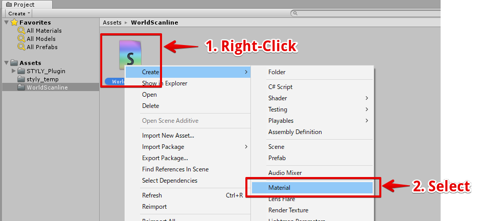
Create a material
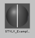
The material created
Assign the material to a Cube
In the Hierarchy window, select ‘Create > 3D Object > Cube’ to create a Cube object.
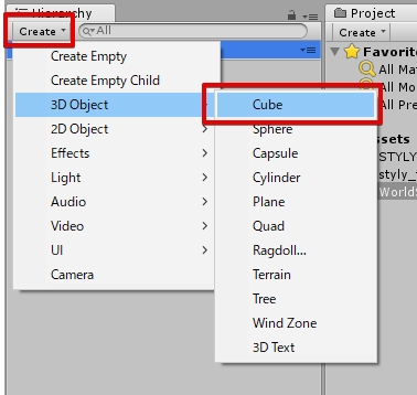
Crate a Cube object.
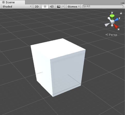
The Cube object created.
Drag the material created earlier into the Cube to assign the material to it.
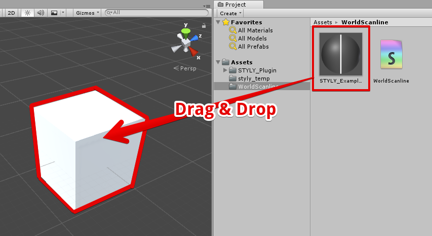
Assign the material to the Cube object.
By playing the game with the scanline material applied, you can see the animated scanline on the Cube.
The result – after applying the material
Create board
Create a ‘Sci-Fi’ board
I explain how to create a board full of Sci-Fi atmosphere.
Render a scanline on the cubes arranged like a board.
Firstly, arrange a lot of Cubes to form the board-like shape as shown below.
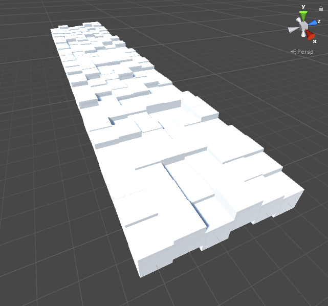
Arrange Cubes
Set the parameters of the material as shown below and assign it to each cube.
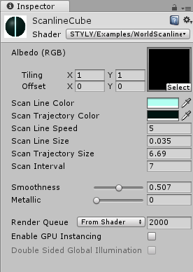
The setting for the material.
Once the material has been applied, the appearance would be like the shown below.
The result – after applying the scanline shader
How to upload an asset from Unity to STYLY
Please refer to the article below to learn how to upload an asset from Unity to STYLY. https://styly.cc/ja/manual/unity-asset-uploader/