- 1 Introduction
- 2 Required Development Environment
- 3 Download Houdini
- 4 Install Houdini
- 5 Launch Houdini
- 6 User Interface Basics
- 7 Darken the Background Color in Scene View
- 8 Houdini Basics: Create a Node in Network
- 9 Houdini Basics: Move Across the Levels in Network
- 10 Create a Table
- 11 Note: The Setting for Houdini’s UI
Introduction
I will show how to create a simple 3D model with Houdini, 3DCG software developed by Side Effects Software Inc.
You can upload the created 3D model to STYLY by exporting it as a OBJ-format file.
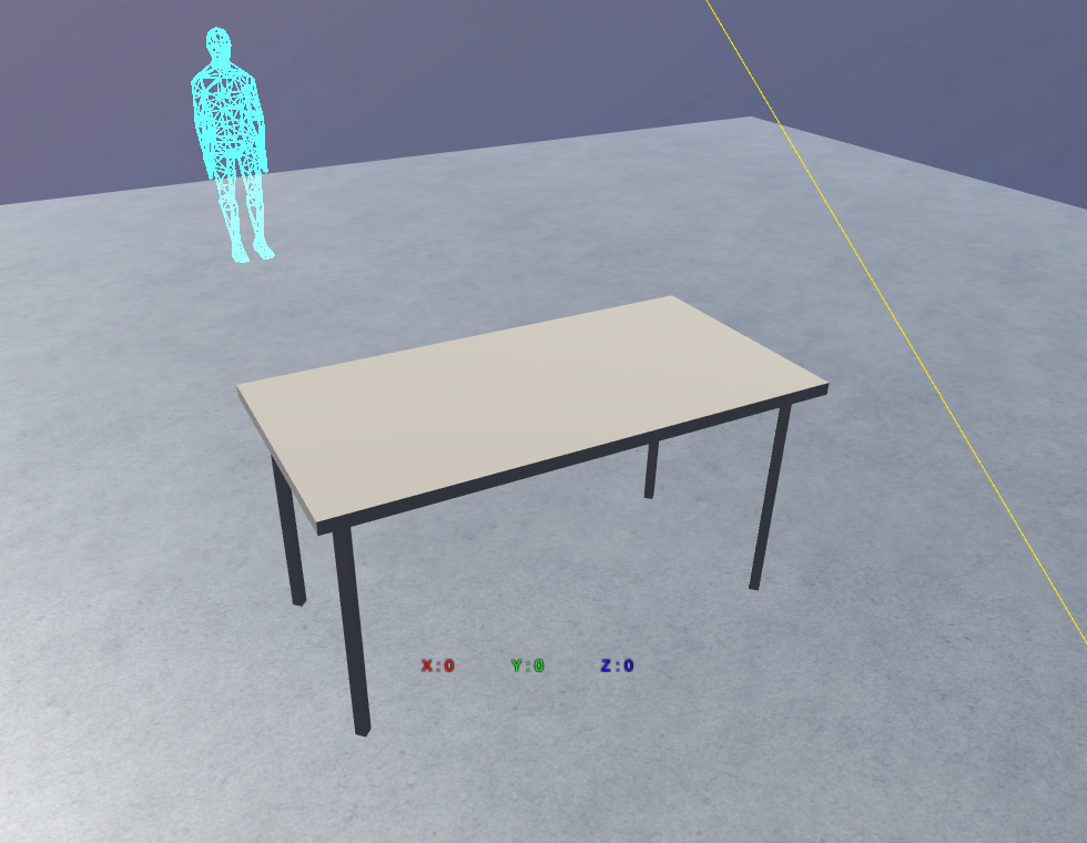
The 3D model we created this time
Required Development Environment
Windows 10
Houdini 17.5
Download Houdini
Download Houdini from SideFx.
Click ‘Get > Download’ in the menu at the top of the screen.

Click ‘Download’
It brings up the login window.
If you don’t have an account, create it from the ‘Register’ form on the right side of the screen.

The ‘Login’ screen
After logging in, the ‘Download’ screen is displayed.

After logging in, the ‘Download’ screen is displayed.
Press the ‘Download’ button to start downloading the installer for Houdini.
Install Houdini
Run the Installer
Run the installer that was downloaded.
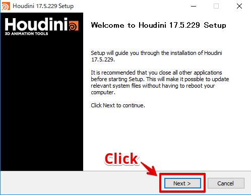
Screenshot – just after launching the installer
License Agreement
Click ‘I Agree’ to see License Agreement.
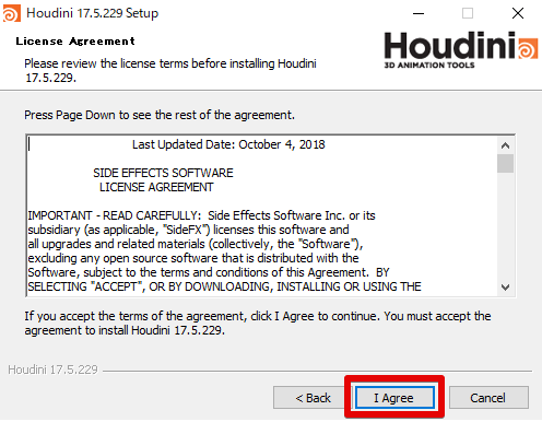
The ‘License Agreement’ window
Select Components to Install
The next window ‘Choose Components’ will appear. Just click ‘Next’ without changing anything.
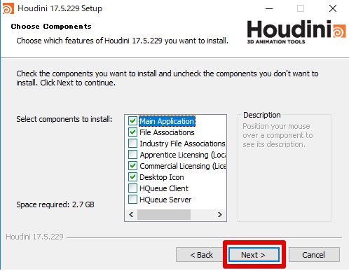
The ‘Choose Components’ screen for the installation
The Setting for Houdini Engine
Then, you will be asked if ‘Houdini Engine’ is installed.
Just click ‘Next’ as we don’t use it at this time.
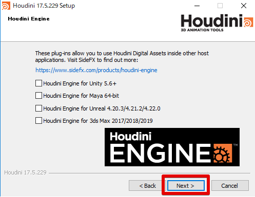
The setting screen for the installation of ‘Houdini Engine’
Set the Install Location for Houdini
Set the install location for Houdini and click ‘Next’.
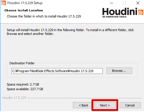
Set the install location for Houdini
Set the ‘Start Menu Folder’
Then, it brings up a window to set the folder name that will be registered with Start Menu.
Just click ‘Next’ without changing anything.
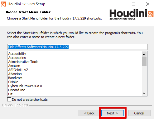
Specify the folder name for ‘Start Menu’
The Setting to Uninstall Old Houdini Version
If the old version of Houdini has been installed, you will be asked if you want to uninstall it.
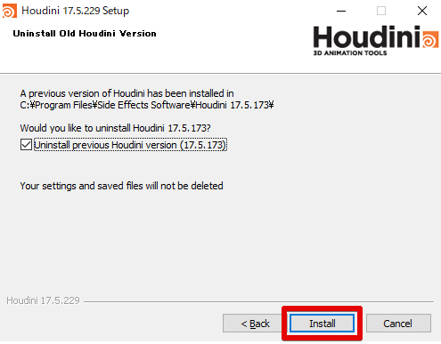
The setting to uninstall the old version
Click the ‘Install’ button to start the installation of Houdini. It may take a little while to install.
The Installation Is Complete
When the installation is completed, the following window pops up. Click ‘Finish’ to close the installer.
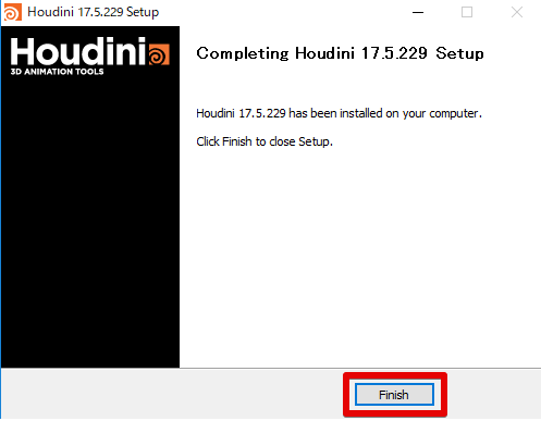
Screenshot – the installation is completed
Launch Houdini
Now, you can find ‘Houdini’ in the Windows Start Menu.
This time, click the free version of ‘Houdini Apprentice’ to launch it.
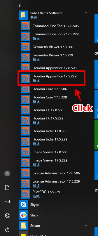
Launch ‘Houdini Apprentice’ from the Start Menu
After launching, you will be asked if you use a free license or paid license.
This time we use the free version of ‘Houdini Apprentice’, so click ‘Next’ without changing anything.
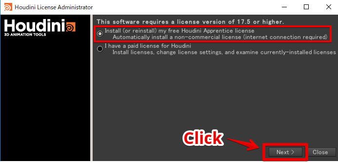
Click ‘Next’ with ‘Apprentice license’ selected
It brings up EULA. Click ‘Accept’.
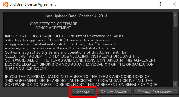
Click ‘Accept’
Then, the ‘non-commercial licenses were successfully installed’ message will appear. Click ‘Run’ to launch ‘Houdini Apprentice’.
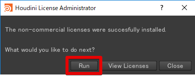
Screenshot – the installation of the license has been completed
‘Non-commercial licenses’ refers to the licenses for ‘Houdini Apprentice’ in this case.
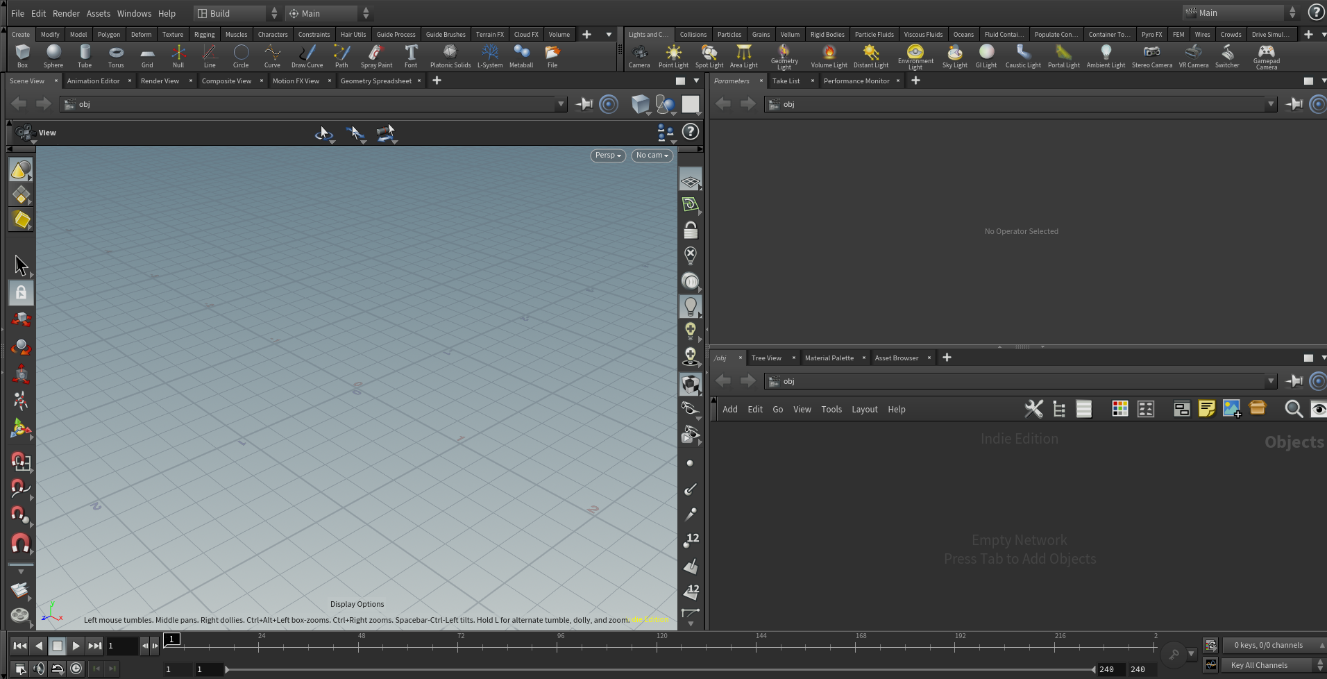
After launching, the following screen appears.
User Interface Basics
This time we use the three windows as shown below.
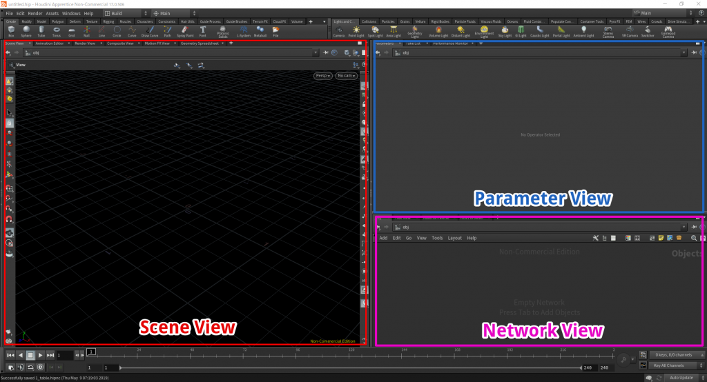
The windows we use this time
Network View
You organize nodes in Network View.
In Houdini, the modelling is carried out by combining nodes.
Scene View
The node with its display flag set to ‘ON’ is displayed in Scene View.
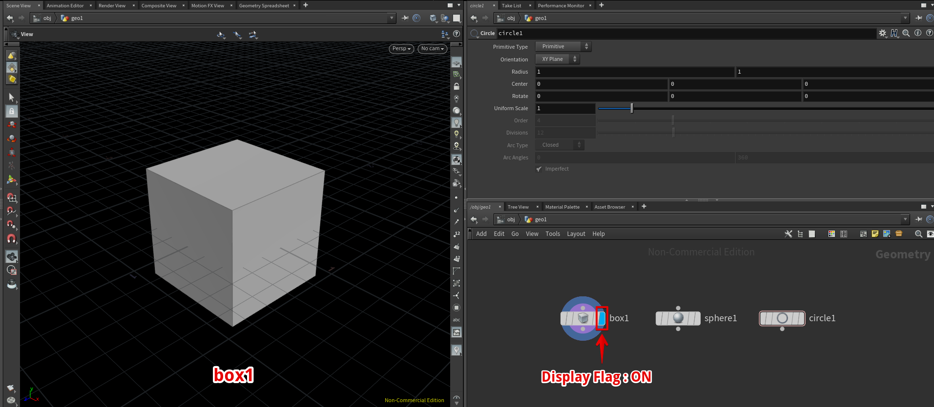
When turning on the display flag of the ‘box1’ node, ‘box1’ is shown in Screen View.

When turning on the display flag of the ‘sphere1’ node, ‘sphere1’ is shown in Screen View.
Note: You can toggle the display flag of a node by clicking on the right edge of the node.
Parameter View
Parameter View displays the parameters for the node selected in Network View.
Darken the Background Color in Scene View
In the default condition, the background color in Scene View is bright. Let’s set it to black to make models easier-to-see.
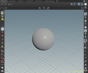
The default background (ColorScheme = Light)
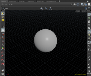
After changing the setting (ColorScheme = Dark)
With the mouse pointer on Scene View, press the ‘D’ key to show ‘Display Options’.
In the Background tab, Set ‘Color Scheme’ to ‘Dark’ to darken the background in Screen View.
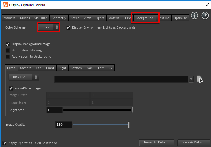
Set ‘Color Scheme’ to ‘Dark’
Click ‘Save as Default’ to keep the background of Screen View black for the next time.
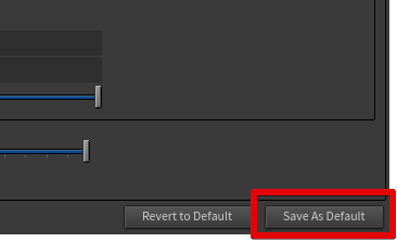
Save the setting by clicking ‘Save as Default’
Houdini Basics: Create a Node in Network
I explain how to create a node in Network View here.
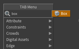
Show the TAB Menu
With the mouse pointer on Network View, press the Tab key or right-click to show the TAB menu.
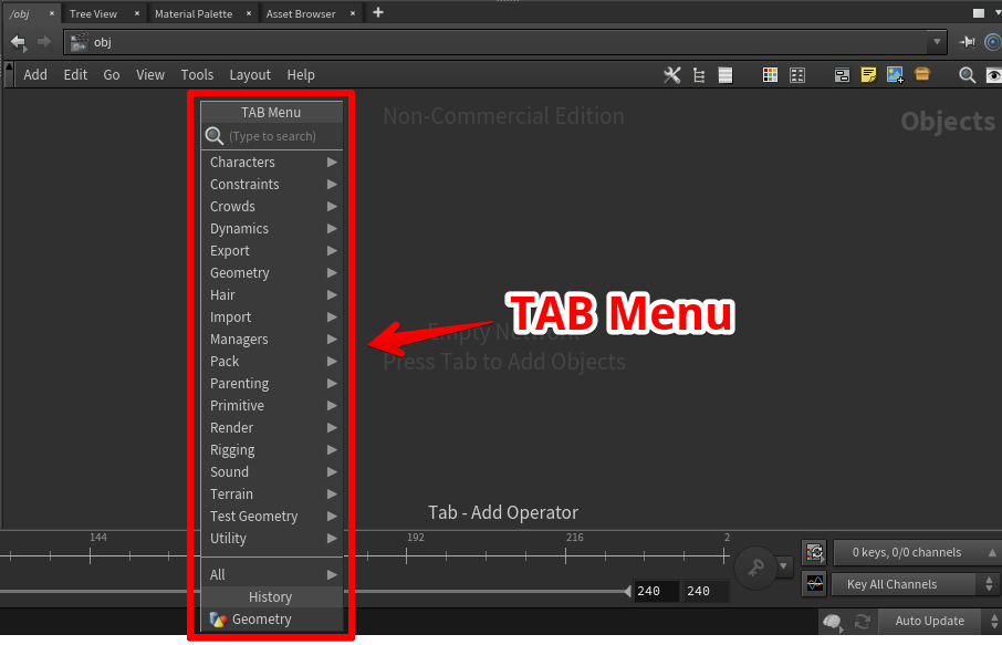
The TAB Menu
The TAB Menu is used to create a node.
Find a Node by Typing
When the TAB Menu is displayed, you can filter nodes by typing a word.
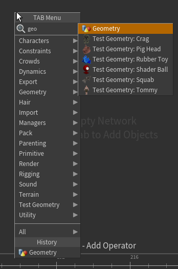
The Geometry node is focused by typing ‘geo’.
Then, press the Enter key once to enter the ‘node creation’ mode.
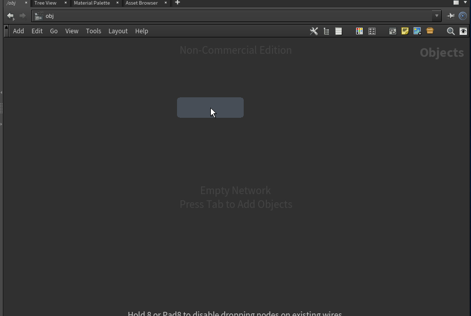
Screenshot – Ready to create a node
Press the Enter key or click the mouse to create a node at the position of the mouse pointer.
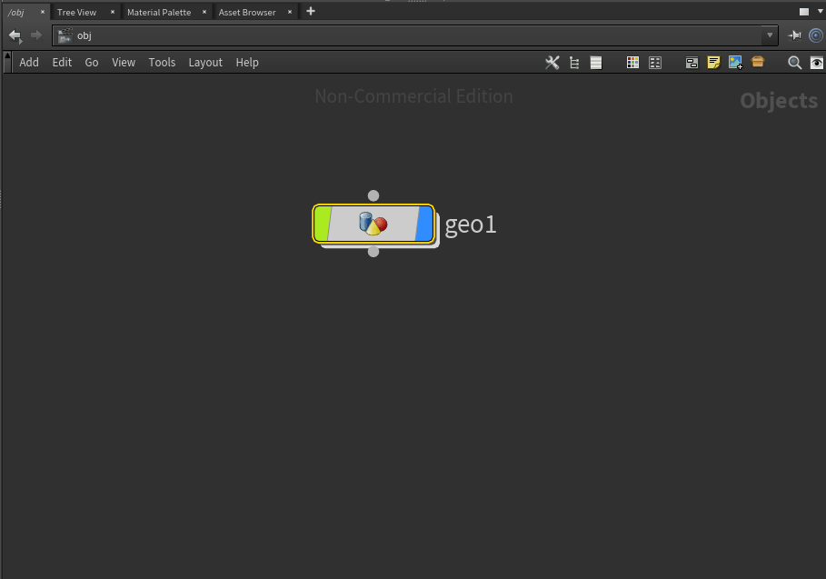
The node created
Connect Nodes
You can connect nodes by dragging the connector with the mouse.
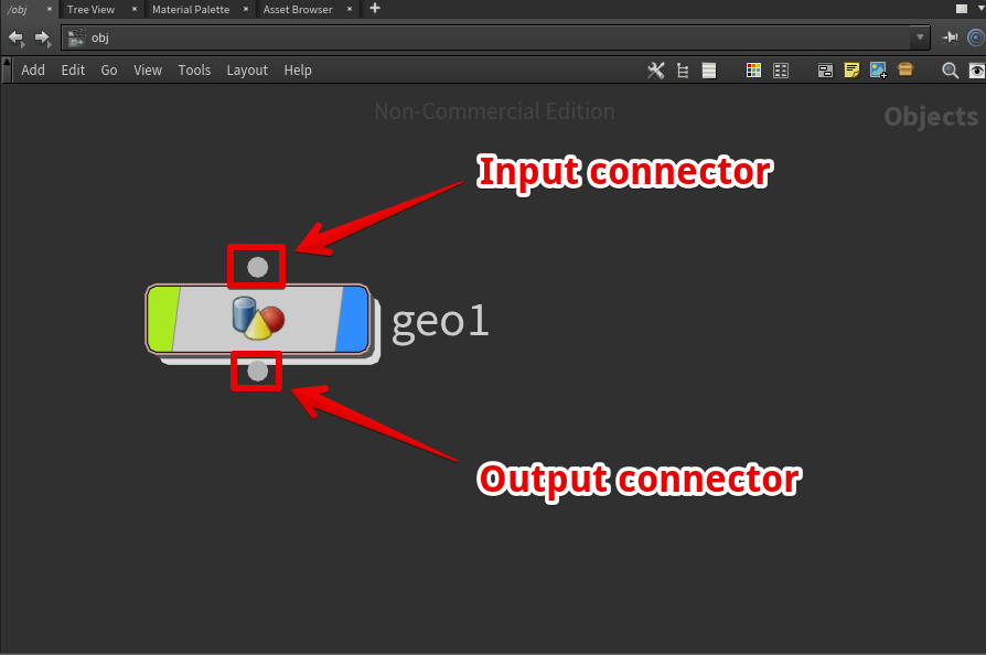
The connectors of a node
Create and Connect a Node at Once
Right-clicking the connector of a node can also bring up the TAB menu.
If you create a node in this condition, you can create a node and connect it to another node at once.
Houdini Basics: Move Across the Levels in Network
Enter a Node
Double-click a node or press the ‘I‘ key with a node selected by the mouse to enter the node.
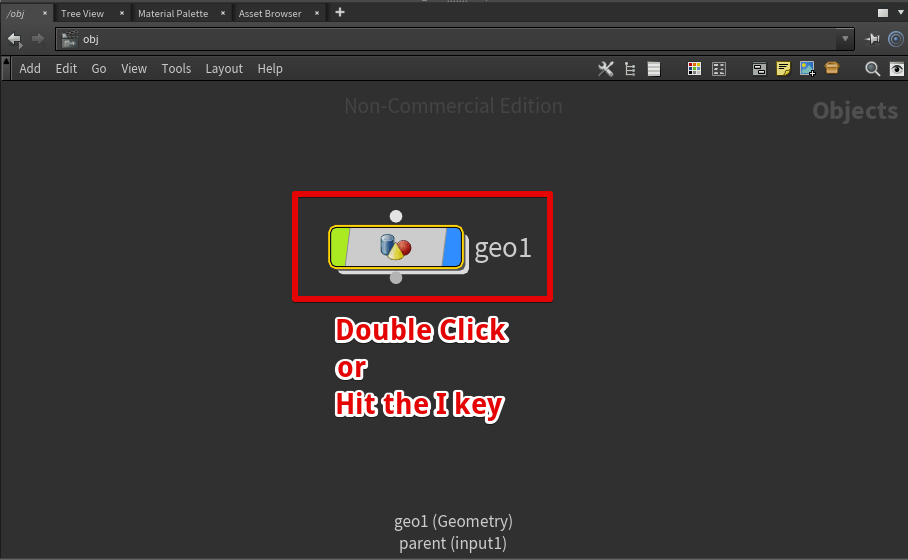
Double-click a node or press the ‘I’ key with a node selected by the mouse
If you entered the ‘geo1’ node, the ‘Path’ in the upper left corner of Network View would show ‘obj/geo1’.
This ‘Path’ shows which level you are in.
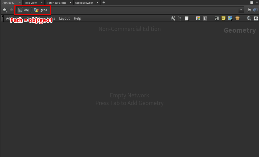
Enter the node
Exit From a Node
Press the ‘U‘ key to return to the upper level.
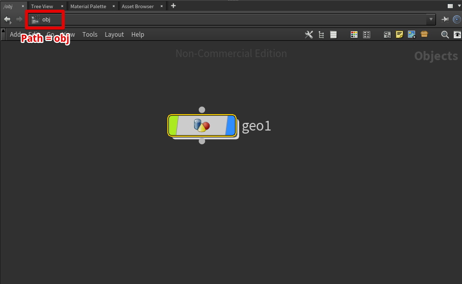
Press the U key to return to the upper level
That’s all for ‘Houdini Basics’.
Useful Operations in Network View
The following shortcuts help you to operate Network View efficiently. The important shortcuts are shown in bold.
The keyboard shortcuts are usable when you put the mouse pointer on Network View.
| Description | Mouse/Keyboard operation |
| Pan | Drag with the middle button |
| Zoom | The mouse wheel |
| Show the whole network | Space + H |
| Display the TAB menu | Tab |
| Undo | Ctrl + Z |
| Redo | Shift + Ctrl + Z / Ctrl + Y |
| Enter the selected node | I / Enter |
| Exit from a node | U |
| Turn on the display flag on a node | R |
| Reverse the input connections on a node | Shift + R |
| Disconnect from any wires | Shake node by the mouse |
| Cut a connection | Y + drag with the left button |
| Focus the selected node | F |
| Jump Back | Alt + the left arrow |
| Jump Next | Alt + the right arrow |
| Layout all nodes | L |
| Layout the selected nodes | Shift + L |
| Move all inputs |
Shift + drag with the left button
|
| Move all outputs |
Ctrl + drag with the left button
|
Create a Table
This time I will show how to create a table with Houdini.
Create a square table
Create an Empty Node
Create a Geometry node.
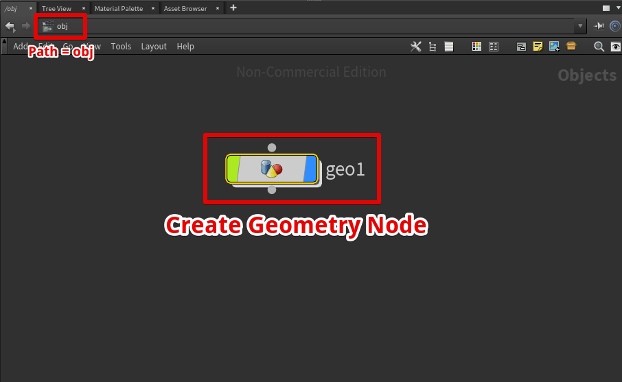
Create a Geometry node
The node is named ‘geo1‘.
Create a Table Top
Create a Box
Enter the geo1 node and create a Box node.
Create a Box node
A Box node is created (it’s named ‘box1‘).
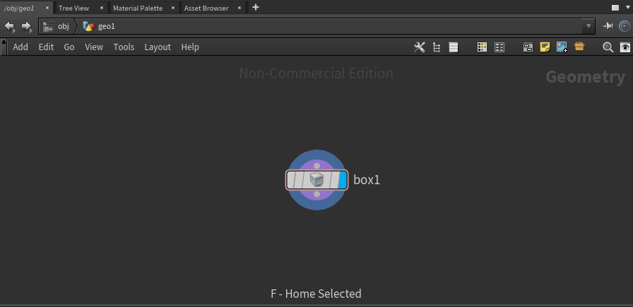
A Box node created
In Scene View, a box is displayed.
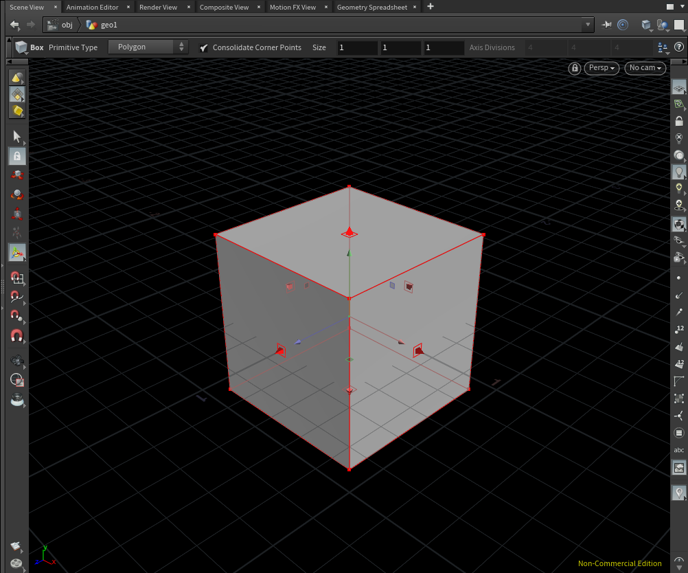
A box is displayed.
Resize the Box
Select the box1 node and set ‘Size X’, ‘Size Y’ and ‘Size Z’ to 2.0, 0.05, and 1.0 respectively.
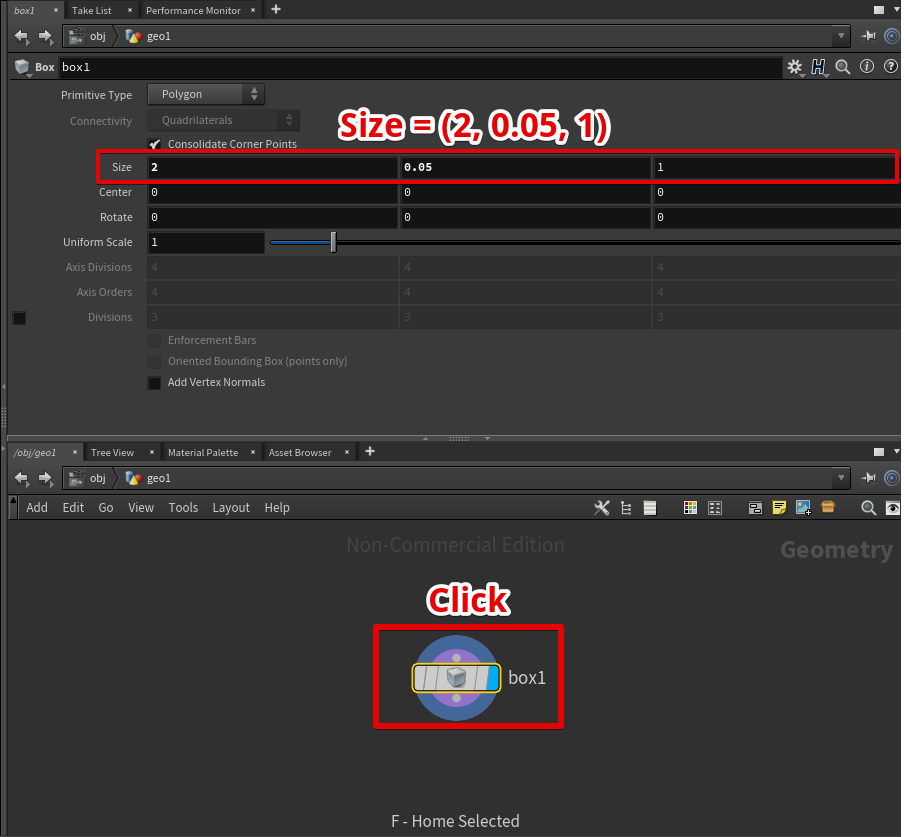
Click the box1 node and set the size to (2, 0.05, 1).
It made the box into a thin board.
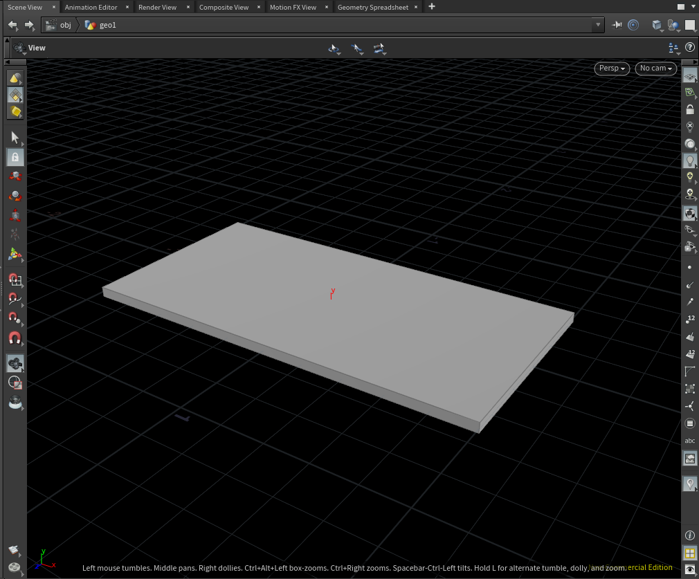
The box with its size set to (2, 0.05, 1)
This completes the table top.
Create the Legs of the Table
Next, we are going to create the legs of the table.
The legs of the table
Create a Leg
Create a Tube node and set its parameters as follows.
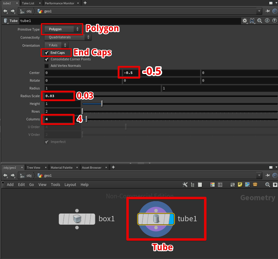
Create a Tube node and set its parameters
In order to display the Tube node in Scene View, you need to turn on the Display flag of the Tube node.
Click the right end of the node or select the node and press the ‘R’ key to turn on the Display flag.
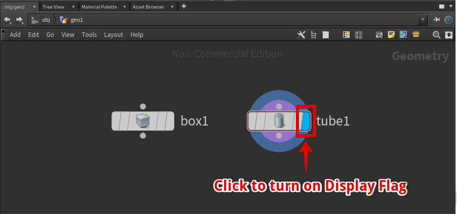
Turn on the Display flag of the Tube node
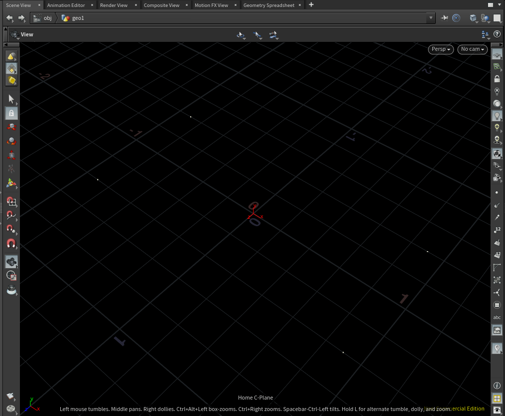
Now, in Scene View, a bar with a square cross-section is placed so that its top face is on the XZ plane.
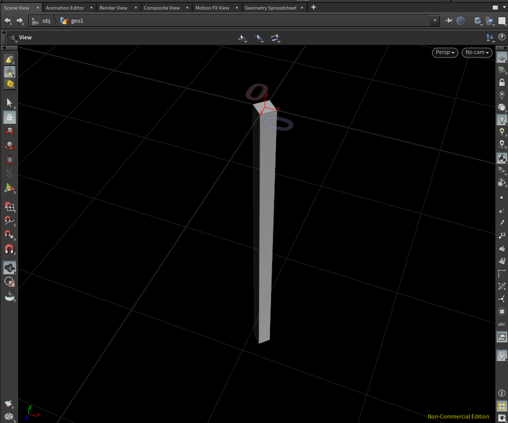
The created Tube
Create Points to Copy the Leg
We copy the leg four times to create the four legs of the table.
It requires four points where you copy the leg.
You can create four points by using a Grid node.
Firstly, create a Grid node and set its parameters as follows.
This time, the table’s size is 2.0 in X and 1.0 in Z. So I set the size in X and Y to 1.8 and 0.8 so that it fits into the inside of the table.
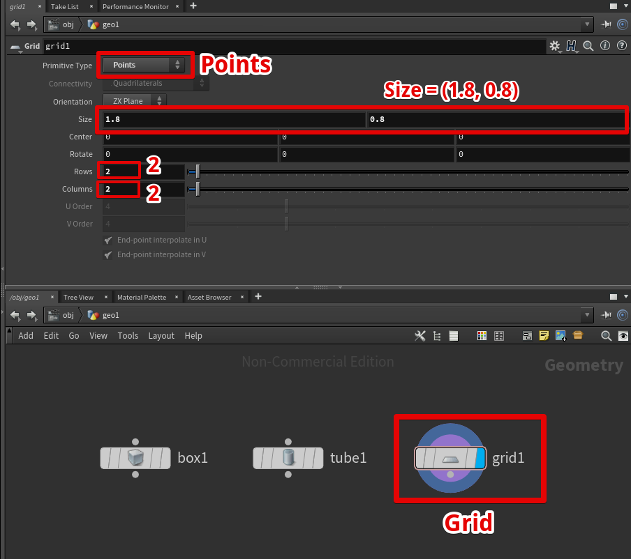
Create a Grid node and set its parameters
Four points have been created.
Four points are created
Copy the Leg to the Points
Copy the leg by using a ‘Copy to Points‘ node.
Connect the geometry to copy with the left connector of the ‘Copy to Points’ node and connect the point where the leg is copied with the right connector.
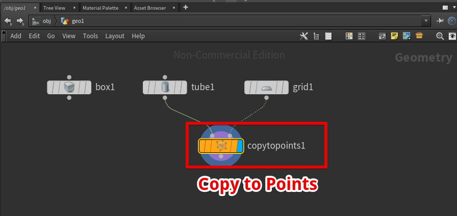
Connect the geometry to copy with the left connector and connect the points where the leg is copied with the right connector.
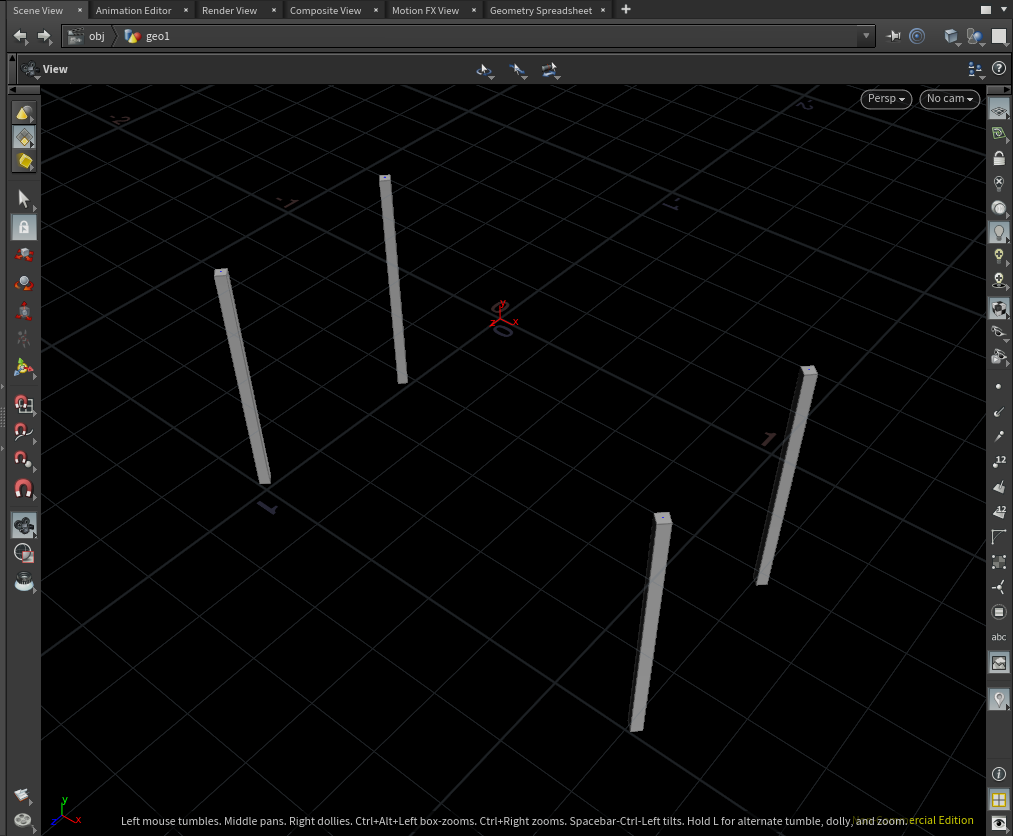
It copies the leg. Four legs are created as there are four points.
Merge the Legs with the Table Top
Create a Merge node to connect ‘copytopoints1’ (the four legs) and ‘box1’ (the table top).
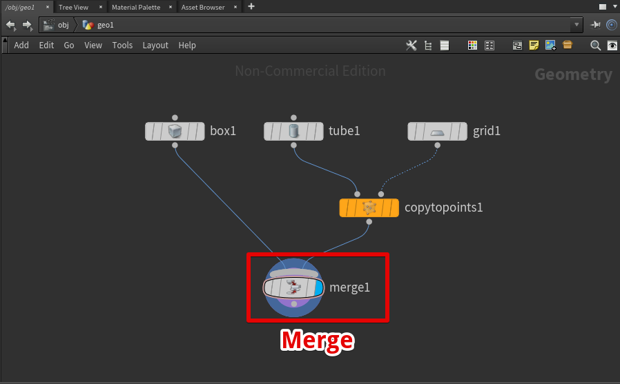
Connect the legs and the table top with the Merge node
The result – the legs have been merged with the tabletop
Shift the Position in the Y Direction
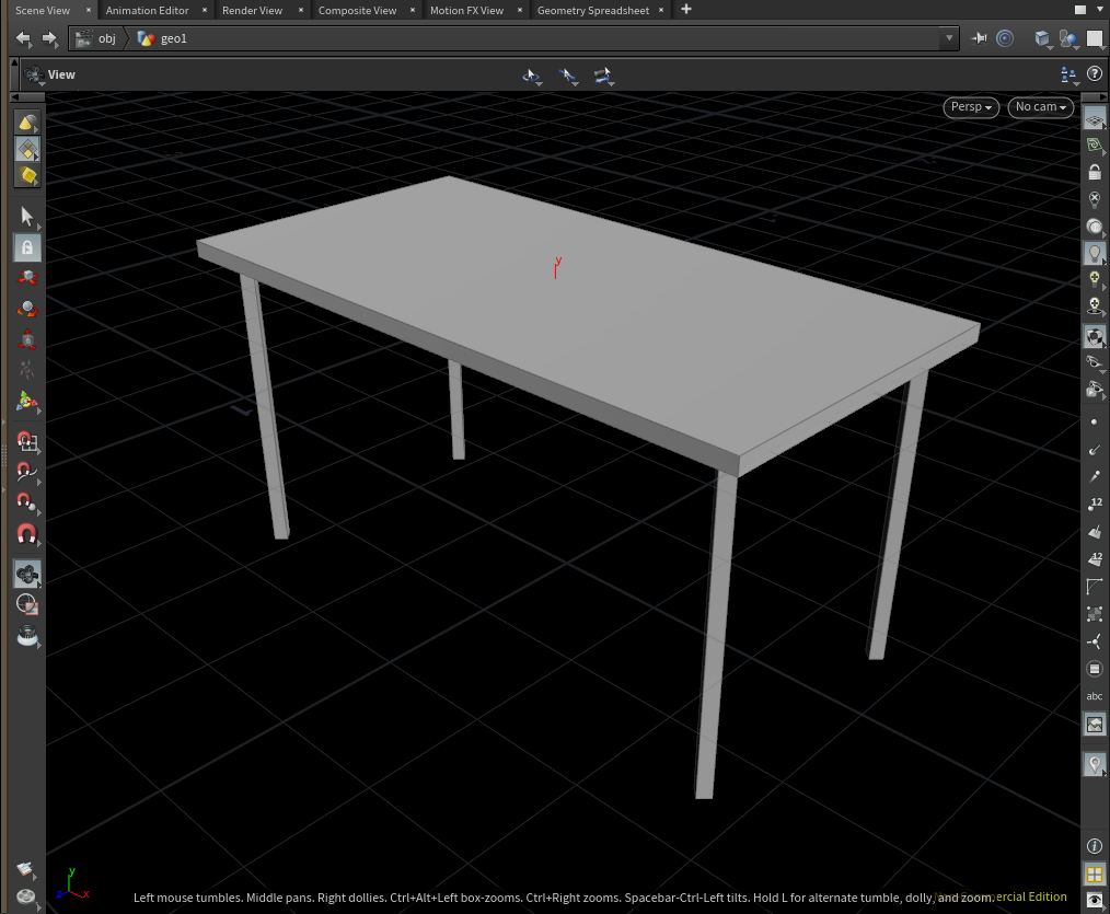
Currently, the table legs extend through the ground (the XZ plane).
The table legs extend through the XZ plane
To correct it, shift the object in the Y direction by using a Transform node.
As the length of each leg is 1.0 this time, set 1.0 for the Y component of ‘Translate’ in the Transform node.
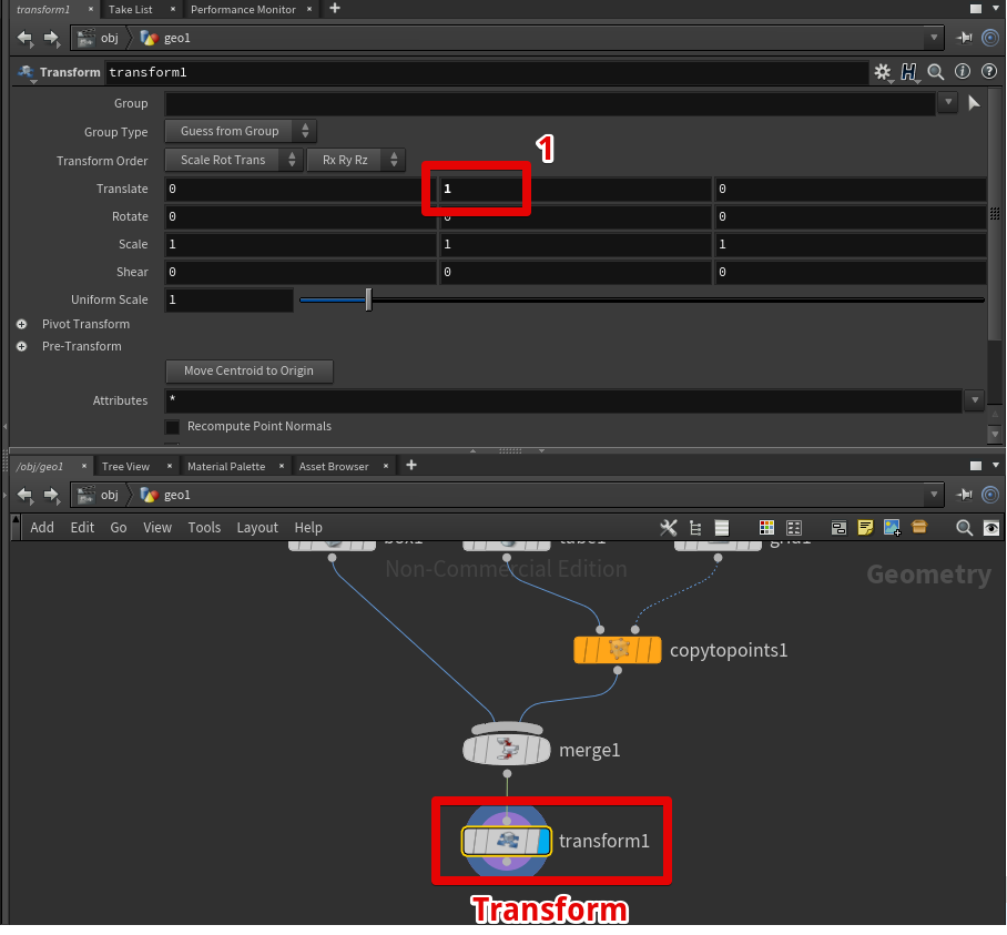
Shift the table in the Y direction by using the Transform node.
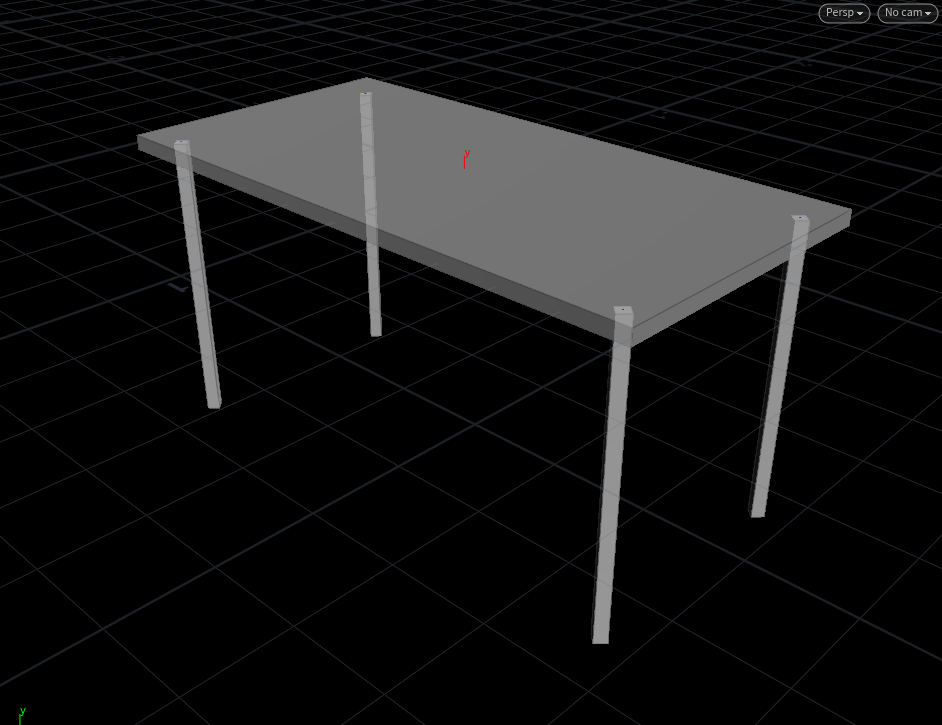
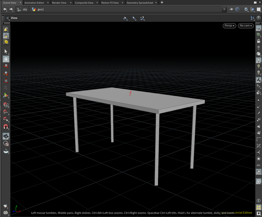
The position of the table has been shifted by +1.0 in the Y direction, so it’s on the ground now.
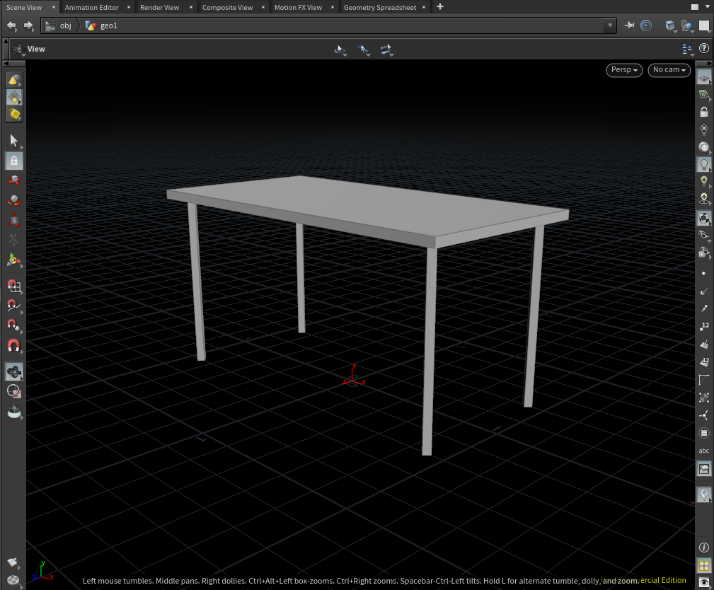
The table is on the ground.
Congratulations. The table is now completed.
OBJ Export
You can upload the 3D table model created above to STYLY by exporting it as an OBJ file.
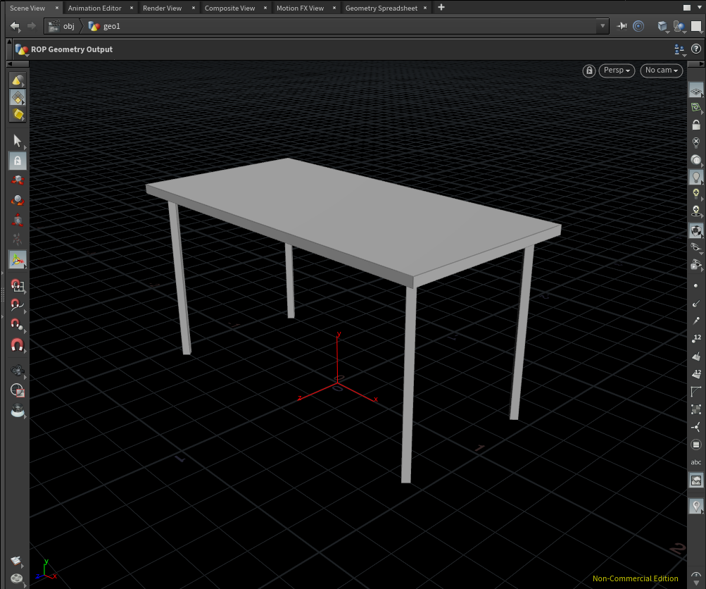
You can export a 3D model as an OBJ file by using a ROP Geometry node.
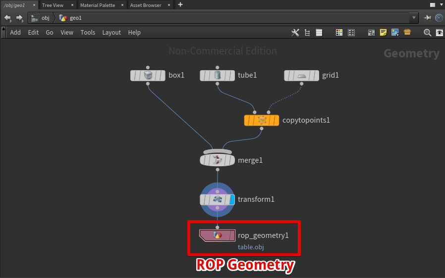
Create a ‘ROP Geometry’ node and connect it to ‘transform1’.
Enter the output path of the OBJ file in the ROP Geometry node (For the extension, you need to type ‘.obj’ manually).
Click ‘Save to Disk’ in the top left corner to export the OBJ file to the file path specified.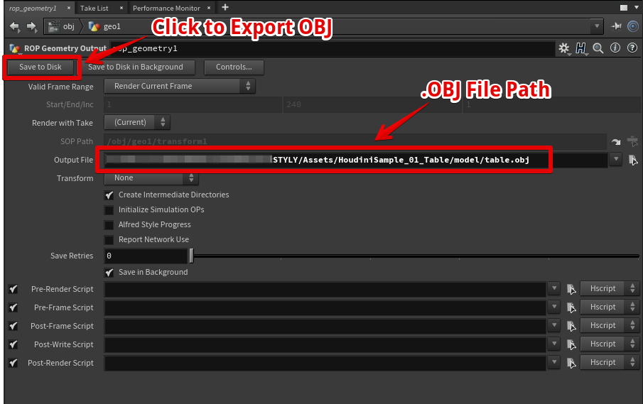
The 3D model is completed now.
Note: Houdini Apprentice Cannot Export FBX
The free version of Houdini Apprentice cannot export a 3D model as FBX.
To export an FBX file, you need a paid licence of Houdini.
The cheapest option, Houdini Indie, costs about 30,000 JPY for the annual subscription.
(As of May 2019)
In addition, you also need a paid license to create VAT (Vertex Animation Texture) etc.
Upload to STYLY
You can upload an OBJ file from Unity to STYLY.
How to upload an asset from Unity to STYLY
How it looks after uploading to STYLY
Note: The Setting for Houdini’s UI
Adjust the Icon Size of UI
Depending on the resolution of the monitor, you would find the UI’s icons at the top of the screen too large.
In that case, you can adjust the icon size.
Select ‘Edit > Preferences > General User Interface’ in the top menu.
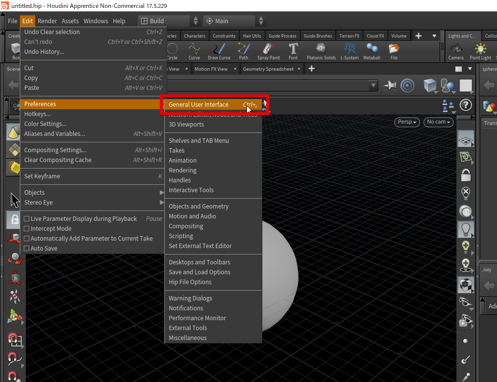
Select ‘Preferences > General User Interface’
You can see the size of icons changing when you change ‘Icon Size and Layout’ or ‘Playbar UI’.
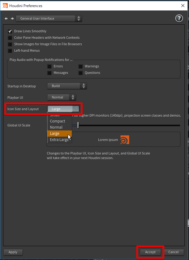
Select ‘Icon Size and Layout’ to change the size of icons
Press ‘Accept’ and then restart Houdini to apply the icon size you set to the UI.
UI Settings Are Saved in ui.pref
In the case of Windows10, the settings are saved in the following file.
C:\Users\{USERNAME}\Documents\houdini17.5\ui.pref
You can directly edit ‘ui.pref’ to change the size of UI.
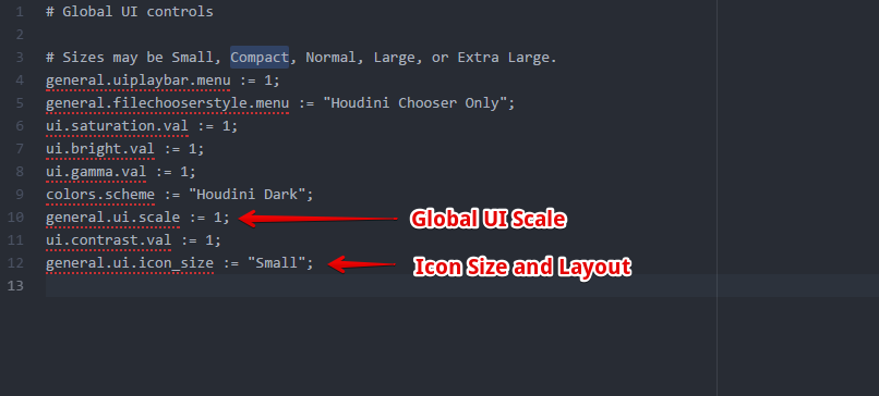
The settings for UI are saved in ‘ui.pref’.