This article is a tutorial for 3dsMax beginners on how to create a model using primitives.
Choose [Box] from the basic primitive. Create a [Spline] from Line, and create a single object.
※I am using Windows10 for this tutorial.
Preparations
Before starting to create a model with primitives using 3dsMax, first check that you have everything ready for this tutorial.
Install 3dsMax
I suppose that anybody who is reading the 3rd article in this tutorial series should already have 3dsmax installed.
If you have not installed 3dsmax yet, please start with the previous tutorial here.
![[3ds Max Tutorial] How to install and launch [Part 1]](https://styly.cc/wp-content/uploads/2019/04/022-160x160.png)
Basic Knowledge Regarding the Tools
Have you finished the previous tutorials and learned the basic knowledge regarding the tools?
If you have doubts and want to review something, please open the previous tutorials from here, and have it ready with you for this tutorial.
![[3ds Max Tutorial] Basic Operations / User Interface [Part 2]](https://styly.cc/wp-content/uploads/2019/05/001-2-160x160.png)
Tools We Are Going to Use
This is a list of the tools we are going to use.
If you have already gained confidence with the basic operations, let’s go on to the next step.
Main Tool Bar
・Move
・Rotate
・Scale
Scene Explorer
・Hidden
・(Group) ※I did not use it, but using it will be useful for sorting your project
Command Panel
・Create
・Edit
Unit Settings
Before starting the modeling, check the unit settings for your display.
If the unit settings are wrong, the object will become created with a different unit, and will have problems to use in different projects.
As in Gulliver’s travels, prevent one object from becoming too large by making sure to change the units to millimeters.
Choose [Unit settings] in the [Customize] tab at the screen top.
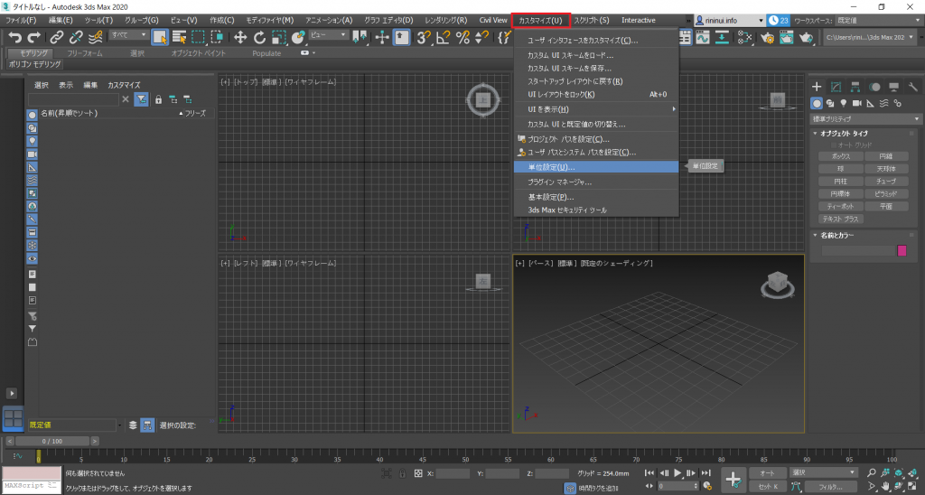
Unit settings 001
Open it and change the unit settings to millimeters.
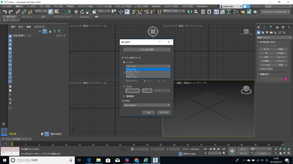
Unit settings 002
Your unit settings are now complete.
Modelling Using Primitives
Create a Box
We are prepared now to start the modelling.
First, go to the command panel, select [Create], then select [Box].
Click on the viewport wherever you like, and create a box.
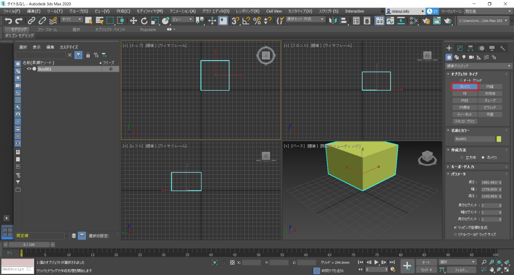
Create Box 001
If you type in a value for the parameters in the command panel, then the box model will become the size you specified.
Of course, you can change the value afterwards from the [Edit] panel.
Let’s move the box you created.
Select the box, and then click on the [Move] tool in the main tool bar.
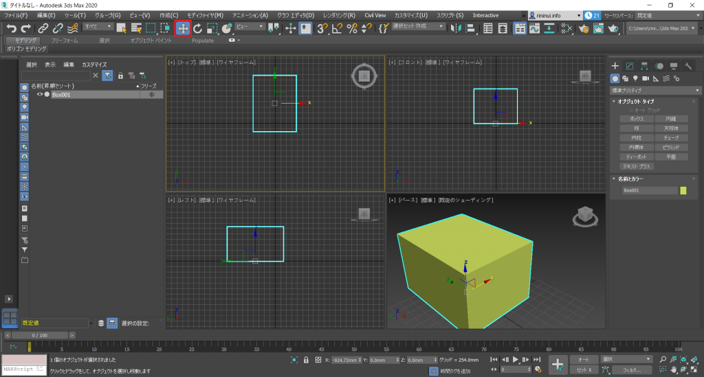
Move Box 001
You can directly move the object, but you can also use the transform gizmo to move the box while fixing an axis.
The [Transform gizmo] is the directional arrows in the center of the object.
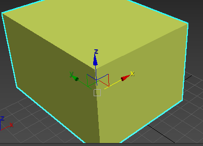
Transform Gizmo 001
If you want to match the object’s position to a certain coordinate, enter the values in the coordinate display area below the view port.
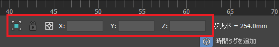
Coordinate display area 001
There are 2 modes in the coordinate display area.
The [Absolute] mode which is based on the world position, and the [Offset] position which is based on an object’s position.
I used the [Absolute] mode, and set all values to 0.
Let’s enlarge the object you created. You can also use the same operation to shrink the object.
Select the box, and then click on the [Scale] tool in the main tool bar.
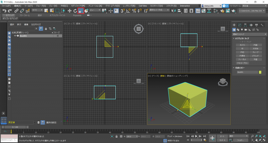
Box Scale 001
There are 3 options for the [Scale] tool transform gizmo.
Enlarge and shrink for the XYZ-axis equally
Enlarge and shrink for 2 of the XYZ-axis
Enlarge and shrink for 1 of the XYZ-axis
You can also use the position display area also.
Lastly, let’s rotate the object.
Select the box, and click on the [Rotate] tool from the main tool bar.
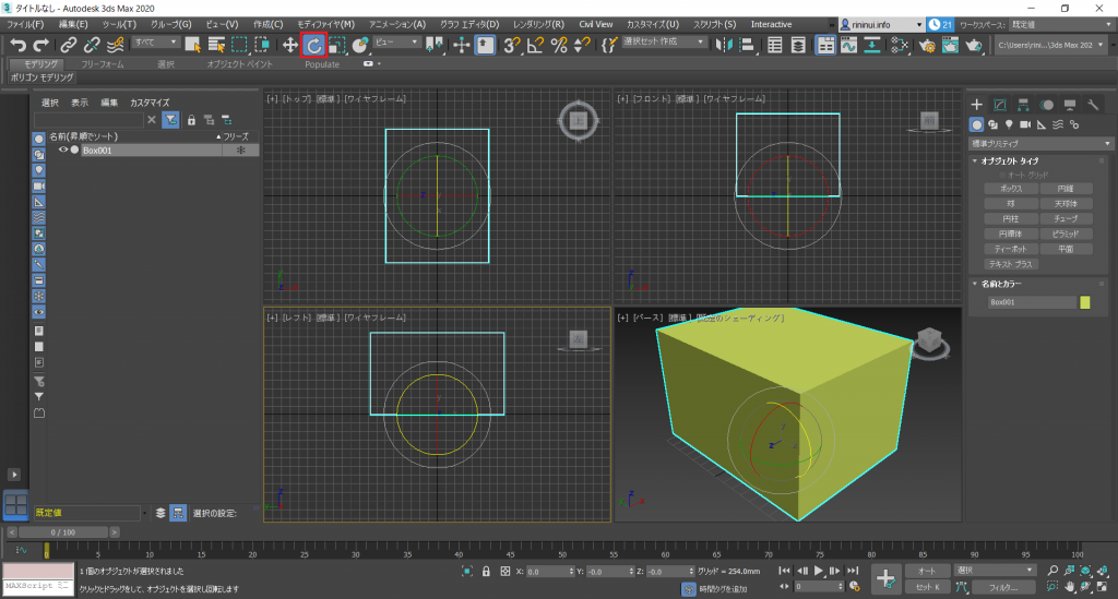
Box Rotation 001
The [Rotate] tool transform gizmo has a standard for each XYZ axis.
You can also use the position display area as in previous steps.
We are now familiar with moving, scaling, and rotating the object, but we do not need to scale or rotate the object for modelling.
Let’s undo the scale and rotate steps.
We will use the [Undo] tool located in the main tool bar. You can also use [Ctrl+Z].
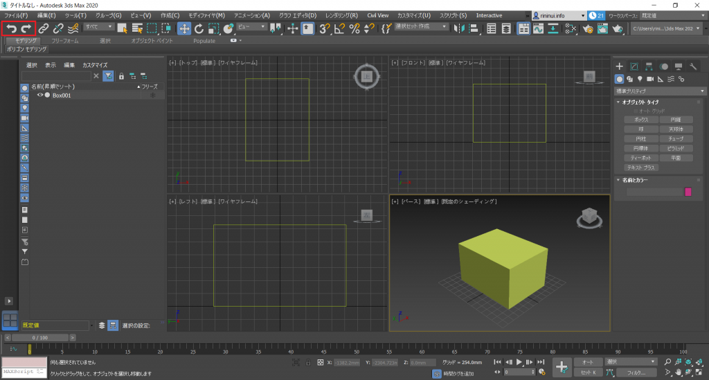
undo 001
Have you ever tried to use [Ctrl+Z] in the real world, and realized that you can’t? I know I have.
But in reality, you cannot undo what you do easily.
As if the world is auto saving itself…
Talking of auto saving, this project isn’t named or saved yet.
Let’s save it immediately. Definitely. You don’t want to cry because your data crashed, do you?
Select [File] in the main tool bar, and then click [Save].
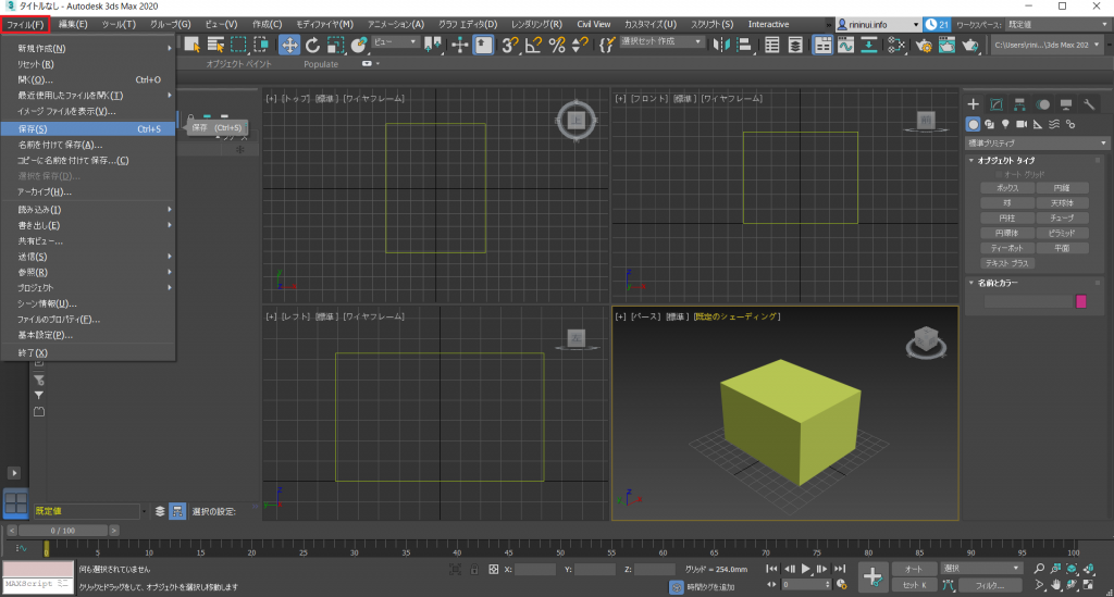
Save 001
Ok, then let’s proceed to the next step.
We will create a new object, so let’s get rid of what we don’t need.
We can delete the box, but we are going to use it for further steps, so let’s [Hide] it for now.
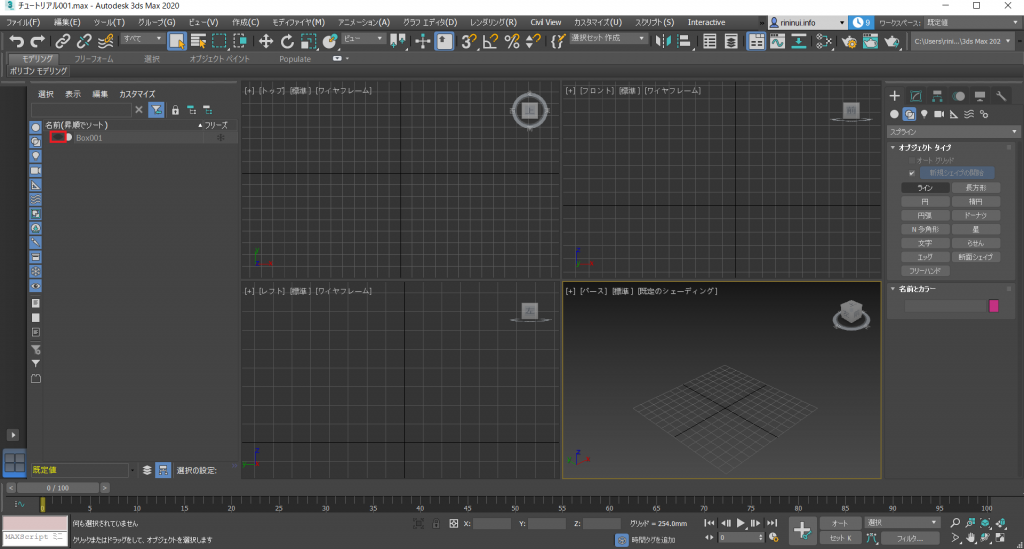
Hide 001
Create Spline
Next, we will use a spline to create a linear. Go to [Create] in the command panel, and choose [Spline].
In the previous tutorial, I didn’t explain so, but the [Create] panel is divided in 7 elements.
[Geometry] Most objects are here. There are not only regular objects such as spheres and cubes, but also teapots and windows.
[Shape] These are objects without thickness, such as lines.
[Light] Lights here.
[Camera] The camera.
[Helper] Objects that help creating a scene.
[Space Warp] Used to create distortion in space.
[System] You will mostly use sunlight and daylight from here, but other functions such as geometry controls to combine objects and levels exists here.
Select [Spline] which is within [Shape]. Then choose [Line].
Click once in the viewport, and that will become the start point for the line. Click again somewhere else in the viewport, and that will become the end point.
If you want to quit creating lines, you can right click to make it linear, or click the start point again to create a closed linear.
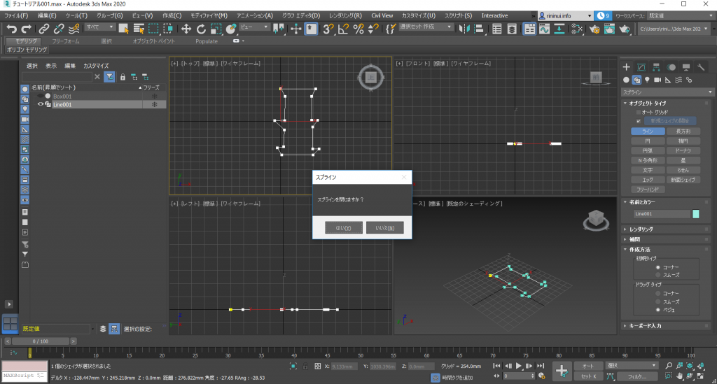
Spline 001
If a message like this pops up, click [Yes] to create the linear.
If you are not satisfied with the shape, or you want to edit the vertice, you can use the [Edit] tool in the command panel to edit them.
What do you do if you want to move a single vertex of a linear?
Click [Select], then select a vertex, then select a segment spline (vertex for this tutorial) to do so.
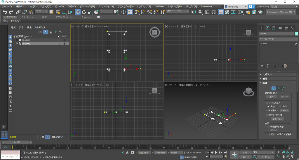
Spline 002
That is it for creating and editing a linear.
But currently, the linear will not become rendered, nor drawn.
Edit Object
At this point, I will explain how to add thickness by combining the line with the box from previous steps, and other edit methods.
First, undo the hide option for the box. If you find that the spline duplicates, I will assure you that you are mistaken.
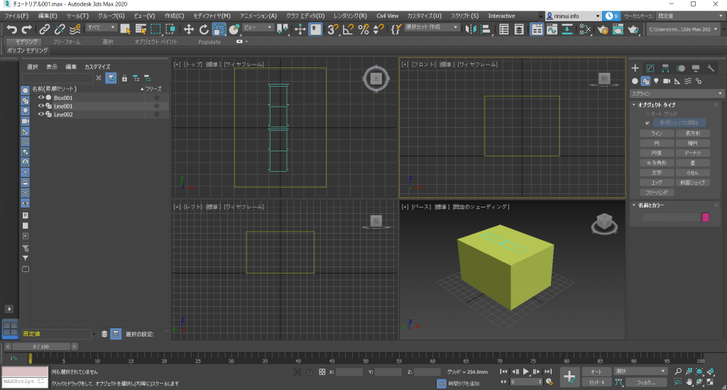
Hide 002
It is not true that I forgot to create a screenshot.
But if you really want to duplicate it, you can create a [Clone]. You can find it in the [Edit] tool in the main tool bar.
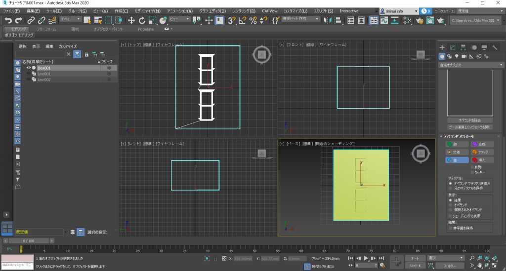
If the box and the spline are in the exact same position, use the move command to move the positions.
Apply the [Sweep] modifier to the created spline.
Sweep is the movement to extrude along a selected spline. For this tutorial, we can use the cross section to add thickness to the spline.
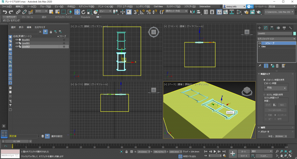
Sweep 001
Choose any cross section type you like. The one I recommend is the oval. You don’t have to change the values either, unless they are really strange.
Maybe you are already aware of something, but please leave it alone for now.
We have one more step to finish this object. Combine the box and and the swept spline, and create a single object.
Select the box, then choose [Create] from the main tool bar, click on [Combine], then on [Boolean operations].
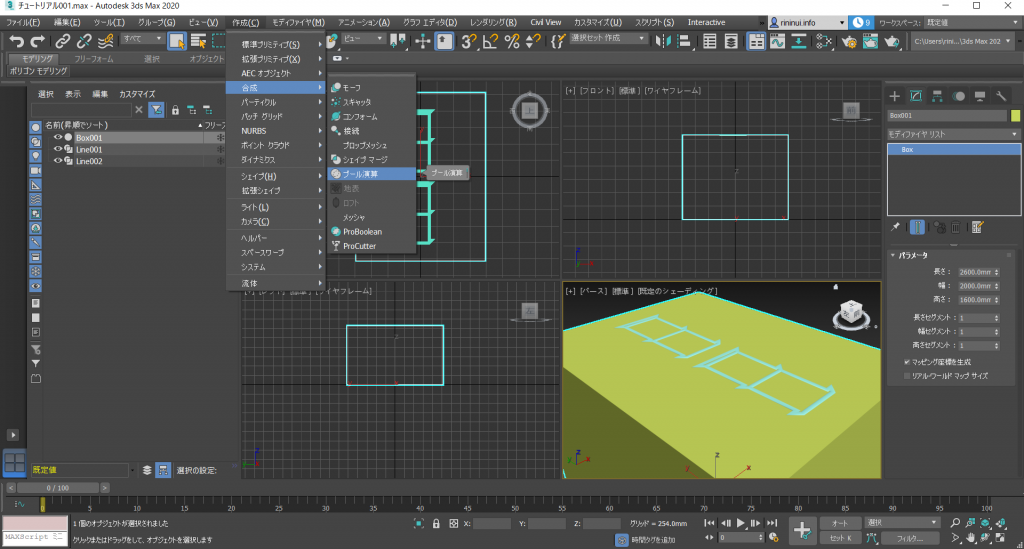
Boolean 001
You might already know, but you can also perform the same steps from the command panel.
Use which ever one that suits you.
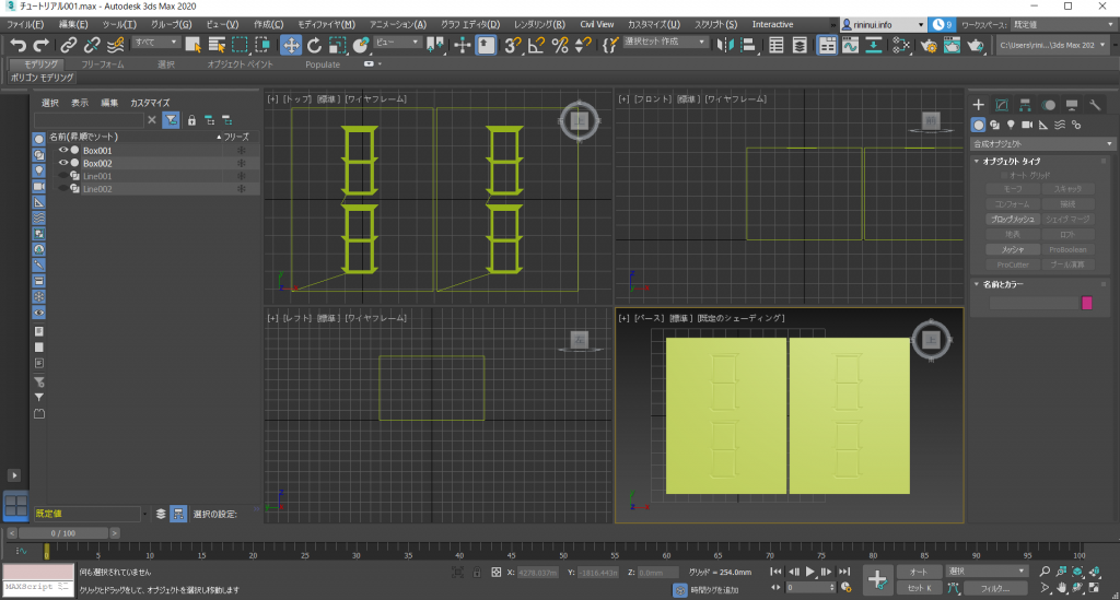
Once you finished the boolean operation, select [Add operand].
Click [Add operand], and then select the object you want to add it to (the spline).
This will just combine them, so change the operand parameter to [Difference].
Boolean 002
A nice 二索(Ryansou) is complete.
Let’s duplicate it.
Duplicate 001
We can almost win!
Let’s use what we have learned from this tutorial to complete the mahjong hand.
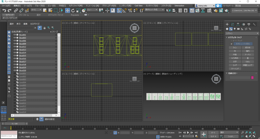
緑一色48000
There are colors in mahjong tiles, I will explain how to add them in the next article, a tutorial for materials.
Conclusion
That’s all for today’s tutorial.
There was a lot of information in this tutorial, but none of these steps are too complicated. Please learn these techniques at your own pace.
Plans for the Next Article
The next tutorial will be for polygon modelling. We don’t have a mahjong table yet, so let’s create one!