In this tutorial, I will explain how to create an object with polygon modeling using 3dsMax.
Note: I used Windows10 in this tutorial.
Preparations
You need to prepare the following before starting this 3dsmax polygon modeling tutorial.
Install 3dsmax
For details on how to install 3dsmax, please refer to this article.
![[3ds Max Tutorial] How to install and launch [Part 1]](https://styly.cc/wp-content/uploads/2019/04/022-160x160.png)
Basic Knowledge About the Tools
Have you gathered basic knowledge about the tools?
If you have doubts, please refer to this article while reading through the tutorial.
![[3ds Max Tutorial] Basic Operations / User Interface [Part 2]](https://styly.cc/wp-content/uploads/2019/05/001-2-160x160.png)
Primitive
Have you mastered primitive modeling?
If you have doubts, please beginning by reviewing this tutorial first.
![[3ds Max Tutorial] Modelling Using Primitives [Tutorial ③]](https://styly.cc/wp-content/uploads/2019/06/xxx-160x160.png)
Previous Tutorial
In the previous tutorial, we learned about the basics of what we need to know before doing polygon modeling.
If you want to go through this tutorial again, please read the related articles here.
![[3ds Max for Beginners] Polygon Modeling – Tutorial ④](https://styly.cc/wp-content/uploads/2019/07/スクリーンショット-24-1-160x160.png)
Polygon Modeling
We will start with real modeling in this tutorial.
First, let’s create an editable polygon.
We went through how to do this in a previous tutorial.
This is the Mahjong tile size we created in a previous tutorial.
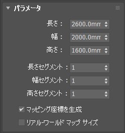
Parameter 1
This time, create the same tile 100 times for a complete Mahjong table.
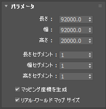
Parameter 2
Change this into an editable polygon. Let’s start the modeling.
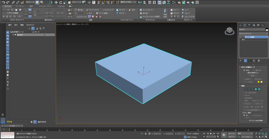
Modeling 1
First, we need to apply a [chamfer] to the edges to make the mahjong table.
[Chamfer] is a command to use for rounding or sharpening corners.
Change the select mode to [Edge], and select the edges you want to chamfer.
Use the □ on the right hand side when you want to change the numeric values precisely, or when you want to add more segments.
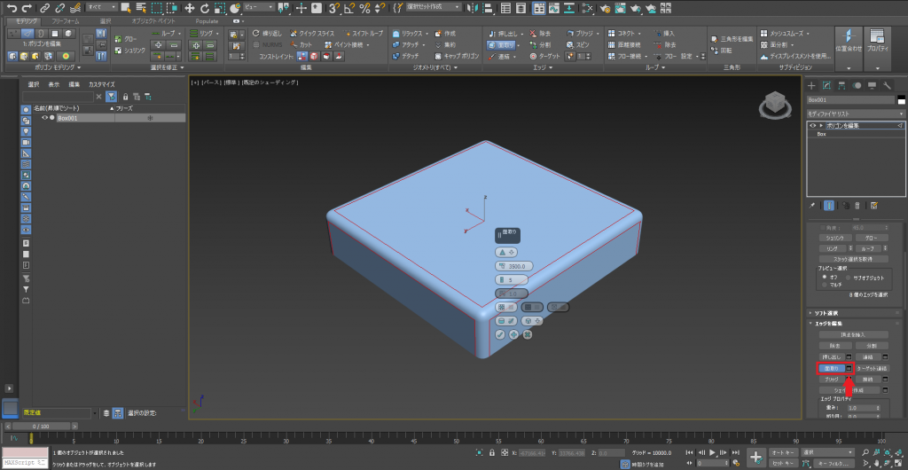
Chamfer 1
Next, we will use [Inset] and [Extrude] to create table rims and the game platform parts.
[Inset] is used to create new faces inside a face.
[Extrude] is used to extrude polygons. You can extrude in the negative direction also.
To create a table rim, I used [Extrude], [Inset], then [Extrude (In the negative direction)].
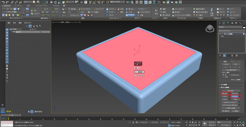
Extrude 1 Inset 1
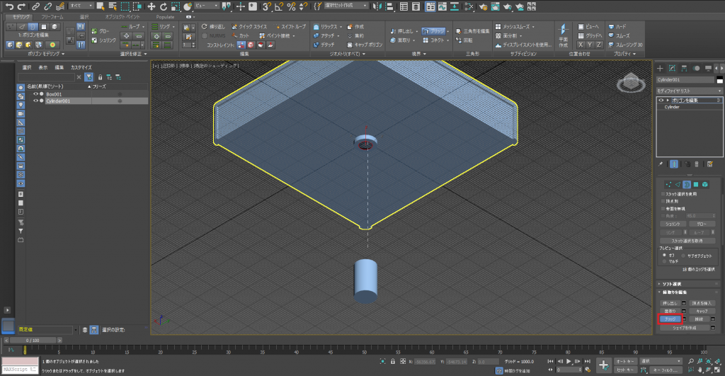
Next, we will create ‘a place to throw dice’.
We are going to use [Bevel] for this.
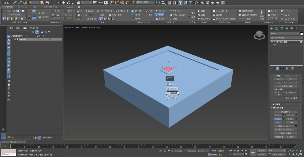
Bevel 1
The basic procedure for beveling is the same as extruding.
Select the polygon you want to edit, and choose apply.
Enter the values.
You can use booleans to make them reachable if you want.
Reach
To make the details richer, I used extrude in the negative direction for the table sides.
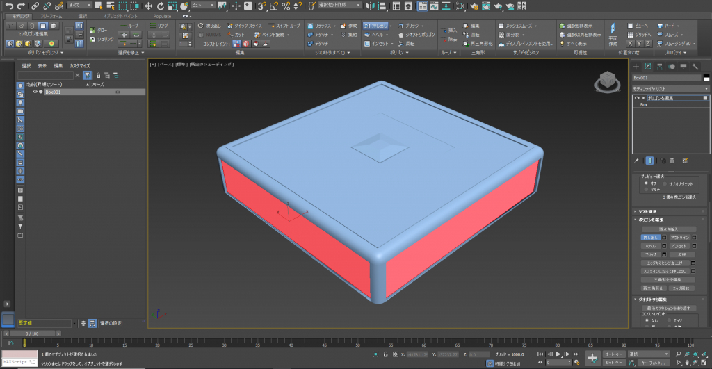
Extrude 2
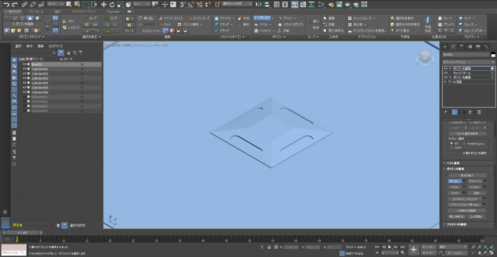
A problem occurred when we do this. A unnecessary face was created, so we need to [delete] it.
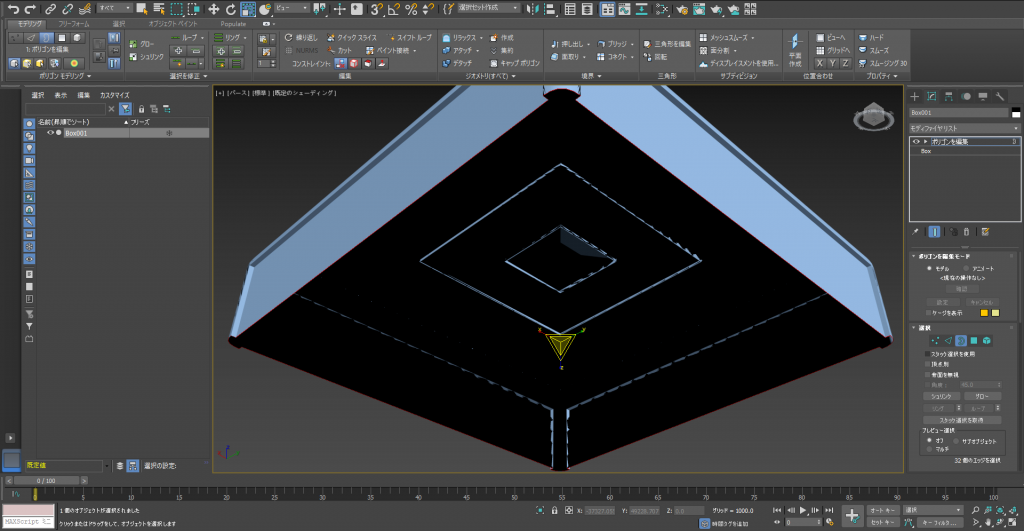
Cap hole 1
Deleting causes a hole to be created in the bottom of the object, so let’s use a [Cap hole].
Change the select type to [Border], select the rim of the face you just deleted.
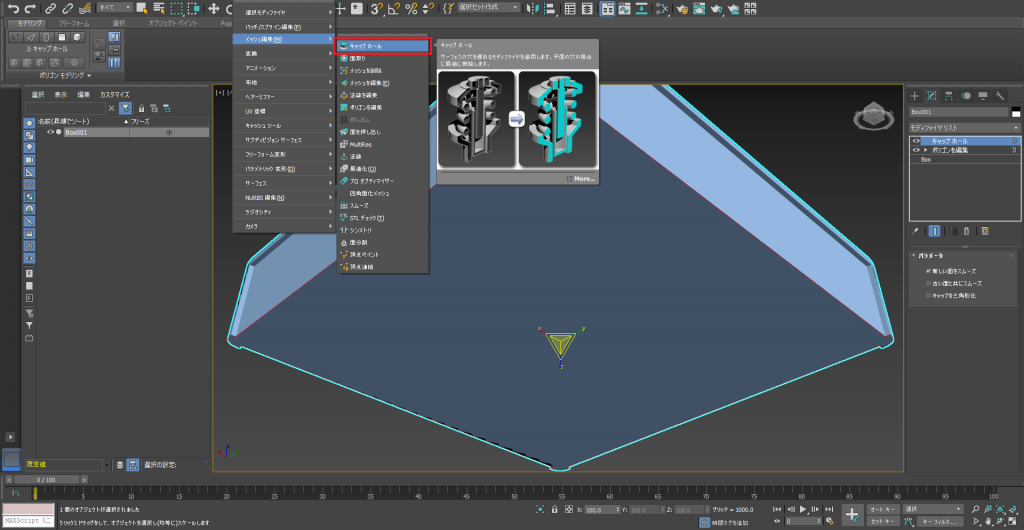
Cap hole 2
Use [Cap hole], and a face will be created.
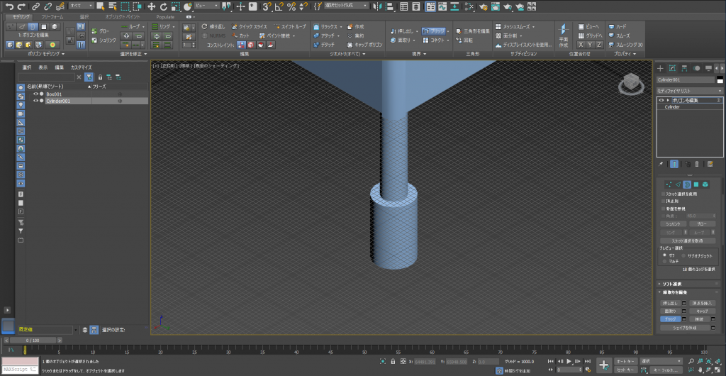
Next, let’s create the prop and table legs.
Place a cylinder and change it into an editable polygon.
Transform it freely, but try not to edit the top and bottom polygons too much.
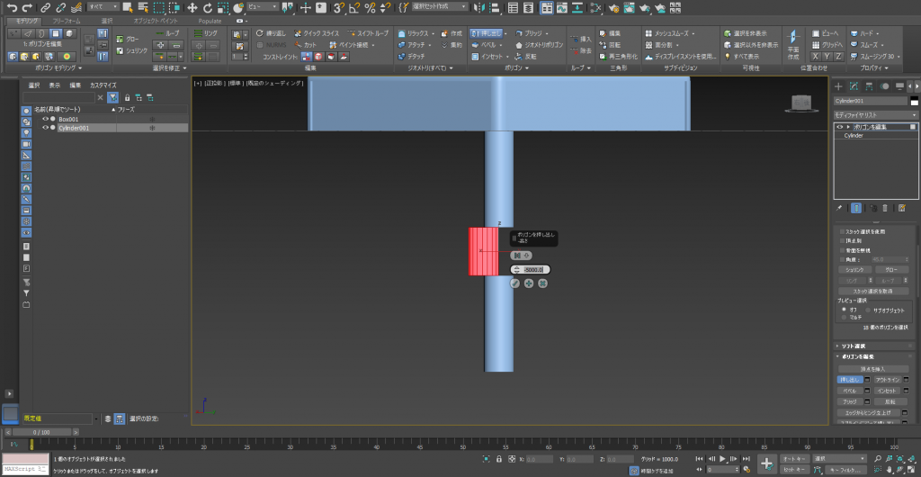
Extrude 3
We used [Extrude], but it’s not perfect. So, go to the top item [Group] in the control, and change it to [Local Aligned].
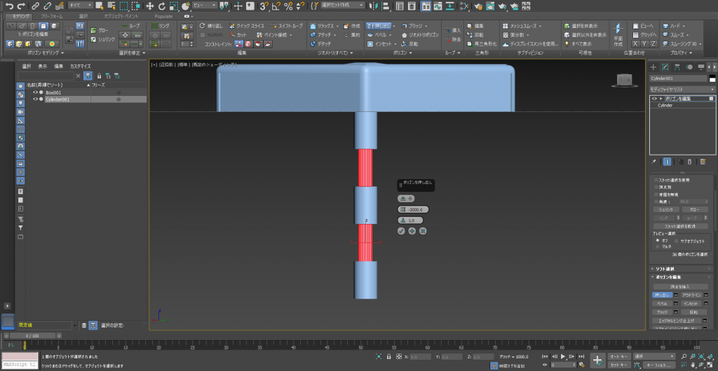
Extrude 4
The result is what we wanted. Delete all the polygons except the top one and the bottom one.
This is additional information, but I will explain about the [Bridge] function.
It connects a rim with another.
Bridge 1
If you click the top and bottom rim in order, a new face is created. It is very average.
Bridge 2
All that is left are the legs. If the legs look cheap, the whole table looks cheap. Let’s try to make them look good. We are going to use some modifiers.
First, let’s create adjusters to attach to the legs.
We will use [FFD] (FreeFormDeformation) for this. This function is more complicated than the previous ones we have dealt with, but it is important and necessary.
Choose [FFD 4×4×4] from the modifier list.
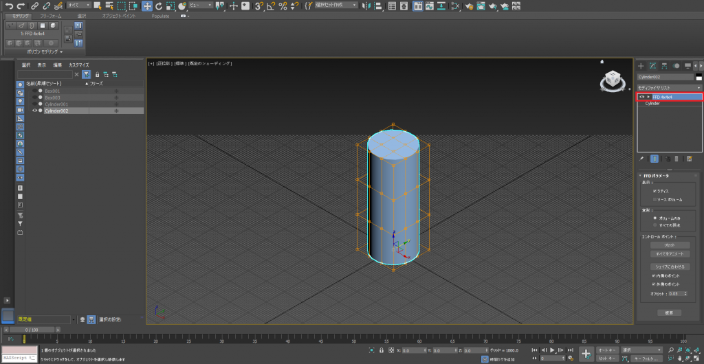
FFD 4×4×4
Confirm that it gets surrounded by a grid, then [Set Volume] to the inside of the stack.
Change the viewpoint and display the top surface.
Each point is editable, just as with normal objects.
Now, we will transform it like the object.
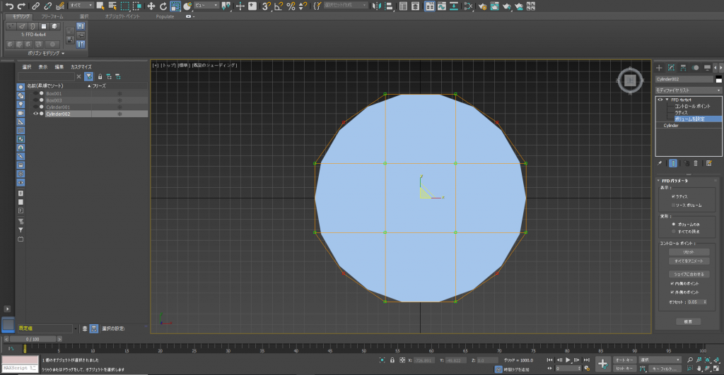
FFD 4×4×4-2
We are done with all the preparation.
Change the select mode from [Set Volume] to [Control point].
We can freely transform it from there, so select each point and edit it.
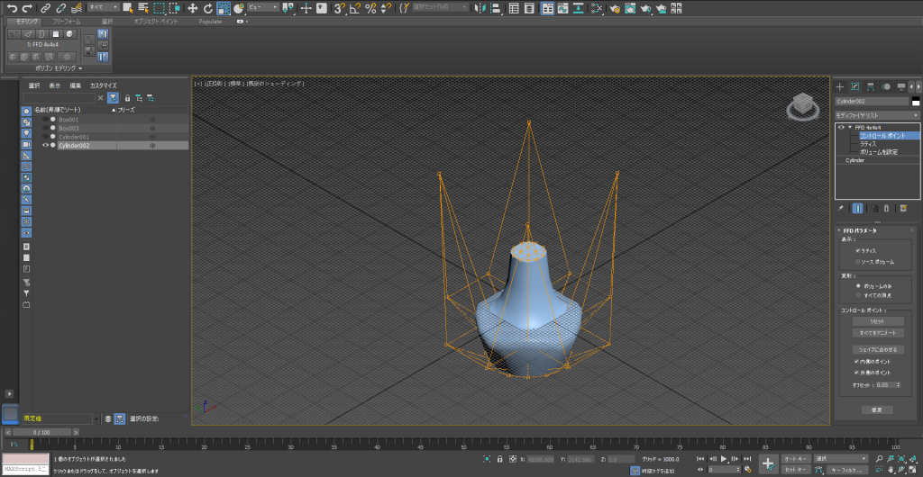
FFD 4×4×4-3
Next, let’s create the legs to attach the adjusters to.
We will use a modifier for this also.
The modifiers we are using are the following.
・[Bend]
・[Taper]
First, create a shape to start from. Create a suitable sized [Box].
Add a number of segments.
The shape changes according to the order you apply the modifiers, so use your creativity to make it look nice.
Use [Bend] next.
[Bend] is a modifier to bend the geometry.
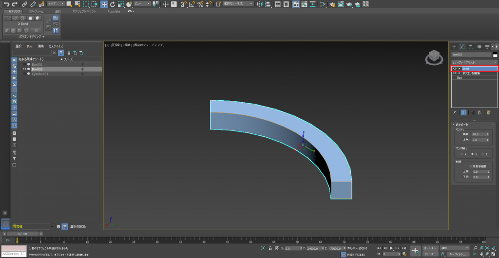
Bend 1
Set an angle and direction, so it matches the shape you want.
Next, use the [Taper].
[Taper] is a modifier that sharpens the geometry.
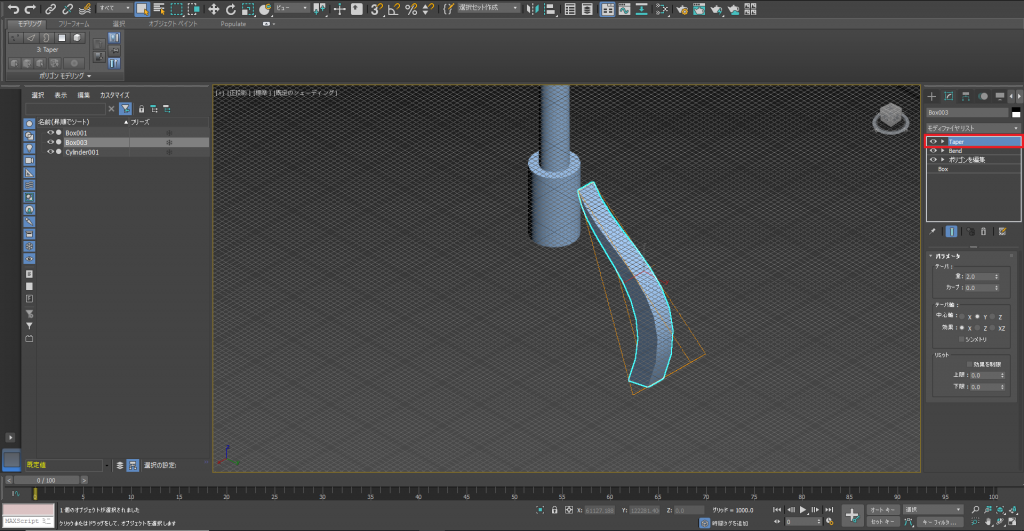
Taper 1
Edit the parameters to create a shape you want.
Place the legs at an appropriate position, and use [Create Array].
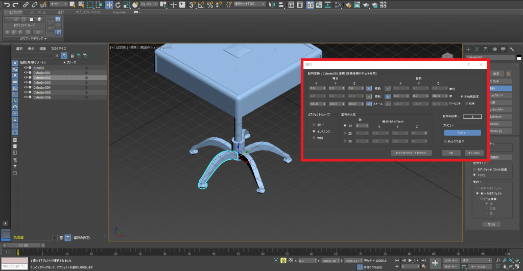
Create Array 1
The last step is to adjust the sizes of each part.
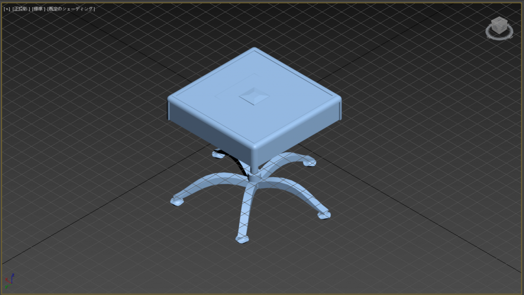
Complete
The mahjong table is now completed and looks great.
Final Notes
You have learned a few of the basics for modeling using 3dsmax.
I hope this tutorial is useful for you and your future modeling.
It will help to master as many of the techniques presented in these tutorials.
This is the last tutorial in this series for modeling for beginners.