In this article, I explain how to arrange the 3D model imported to Unity with Shaders. By adjusting the shader, you can create various visual effects and make the 3Dmodel look quite different. I also introduce some unique shaders that are useful to create Scenes full of originality.
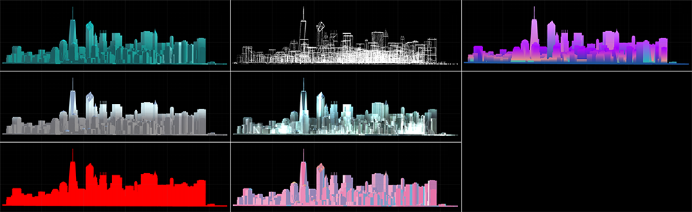
The completion image
Sample
You can taste the sample space in STYLY GALLERY.
You can download the sample project from: STYLY-Unity-Examples
What is Shader?
Shader is ‘a program to define the appearance of an object’. By editing the code of the shader, the appearance of the object changes in various ways. In addition, shaders play an important part when you build up visuals with Unity, STYLY can import most of Unity’s shaders, so let’s make good use of them to render the world you imagined.
Shaders supported by STYLY
Basically, STYLY can import all shaders for Unity. It also supports the shaders designed by node-based visual programming such as ShaderForge (This article explains it in details). However, you cannot use the shader combined with C# script since STYLY cannot import C# scripts. Some shaders in Unity Asset Store include C# script, so please note that STYLY cannot import them.
How to use Shader
I explain the basics to use a shader. You may skip this chapter if you have already used a shader before. In a shader, there are some parameters to control the appearance such as ‘what texture is used’, ‘how much light is reflected’. It’s a material that defines those parameters. So, when you use a shader on Unity, you need to attach a shader to material and set the parameters, then attach it to the object in the Scene.
Change Shader in Unity
Firstly, place the 3D model you want to arrange by a shader, in the Scene. In this tutorial, place a ‘Cube’ in the Scene. Right-click on the Hierarchy window and select ‘3D Object > Cube’ to create a Cube object.
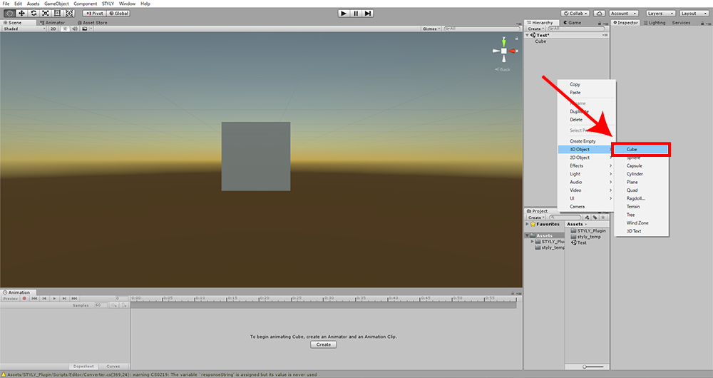
Place a 3D model in the Scene.
Next, let’s create a material. Right-click on the Project window, select ‘Create > Material’ to create it. To avoid confusion, I recommend you to name the material a unique name. I named it ‘New Material 01’ this time.
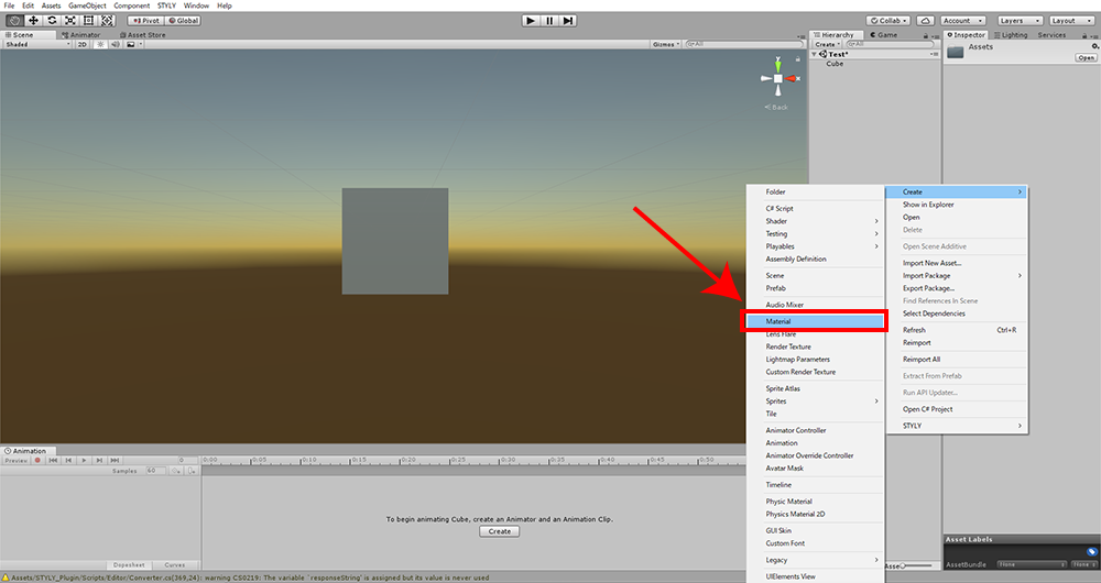
Create a material
You just need to apply ‘New Material 01’ to ‘Cube’ to change the shader as you like. Drag ‘New Material 01’ in the Project window into ‘Cube’ to attach.
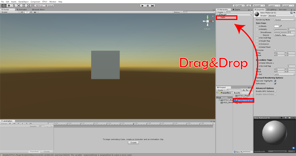
Attach the material.
Now it’s ready to change the shader. Open the Inspector of the object you attached the material to. Now, you can change the shader by the ‘Shader’ drop-down menu. This drop-down menu also shows newly-made shaders and the ones downloaded from Unity Asset Store, so you can select them from this menu as well.
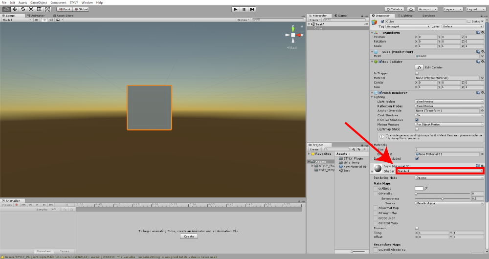
Change the shader.
There are several parameters for the material. So, you can change the appearance of the object by adjusting those parameters.
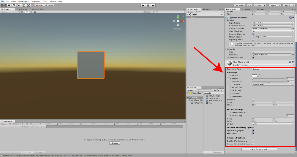
The parameters for the material
Use the shader with the code published to the internet
When you use the shader with the code published to the internet, you need to define that shader by yourself. It might sound difficult at first, but it’s very easy actually. Firstly, right-click on the Project window, select ‘Create > Standard Surface Shader’ to create a new shader. To avoid confusion, I recommend you to name the shader a unique name.
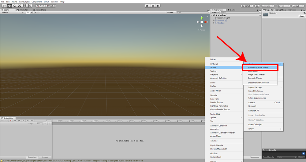
Create a shader
Double-click the created shader to edit its code. Delete all existing codes, and then copy and paste the code of the shader you want to use.
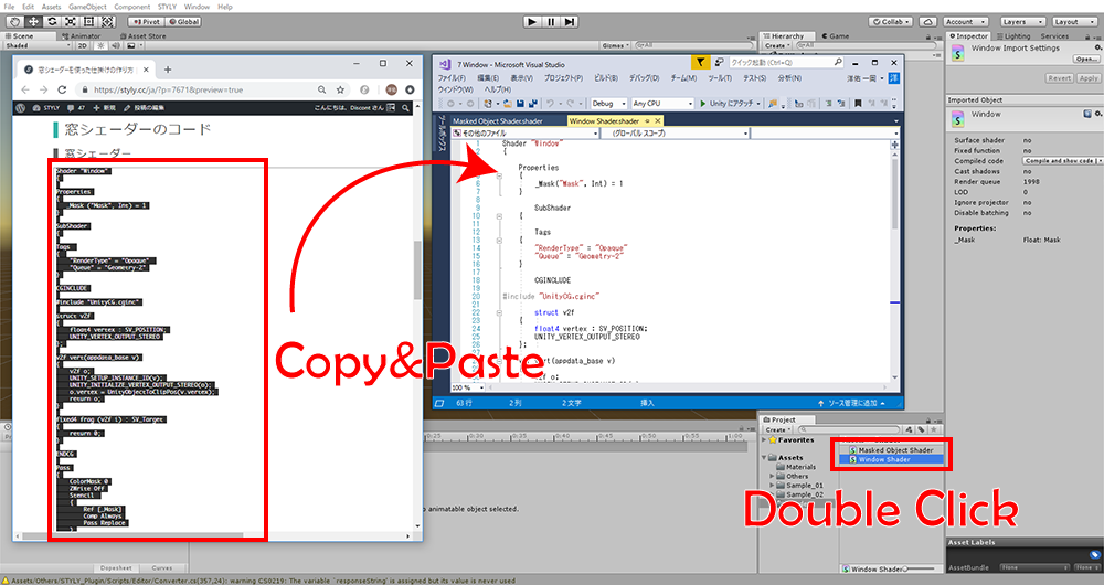
Edit the shader
When you finished editing the shader, save it and go back to Unity’s screen. The shader created in this way also appears in the ‘Shader’ drop-down menu.
Use the shader from Unity Asset Store
There are a variety of unique shaders in Unity Asset Store, so it is also a good idea to use them. A lot of shaders are available for free. When you use a shader available in Unity Asset Store, you just need to press the ‘Import’ button, which allows you to use it in Unity immediately. The shader you import in this way also appears in the ‘Shader’ drop-down menu.
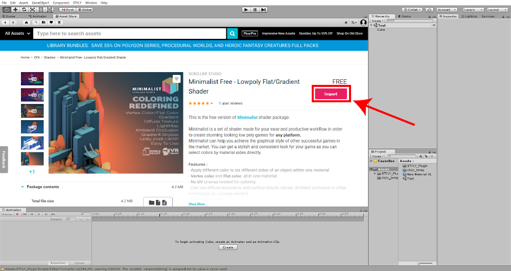
Import an asset from Unity Asset Store
Arrange the appearance with Unity’s shaders
In this chapter, I explain how to arrange the appearance of a 3D model by modifying the parameters of Unity’s shader.
Render plastic-like or metal-like texture by using Unity’s Standard Shader
‘Standard Shader’ is the default shader in Unity. To use ‘Standard Shader’, open the Inspector of the material and select ‘Standard’ from the ‘Shader’ drop-down menu.
Standard Shader
Unity’s ‘Standard Shader’ has some parameters such as ‘Metallic’, ‘Smoothness’, so you can render various textures like plastic or metal. Simply put, the appearance gets more ‘metallic’ by setting ‘Metallic’ closer to 1 while it gets ‘smoother’ by setting ‘Smoothness’ closer to 1.
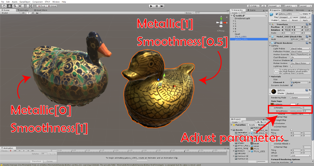
Adjust the parameters.
You can arrange the appearance of an object by adjusting those two parameters appropriately. If you want to learn more about the material parameters of Unity’s Standard Shader, I recommend you to read the Official Unity User Manual.
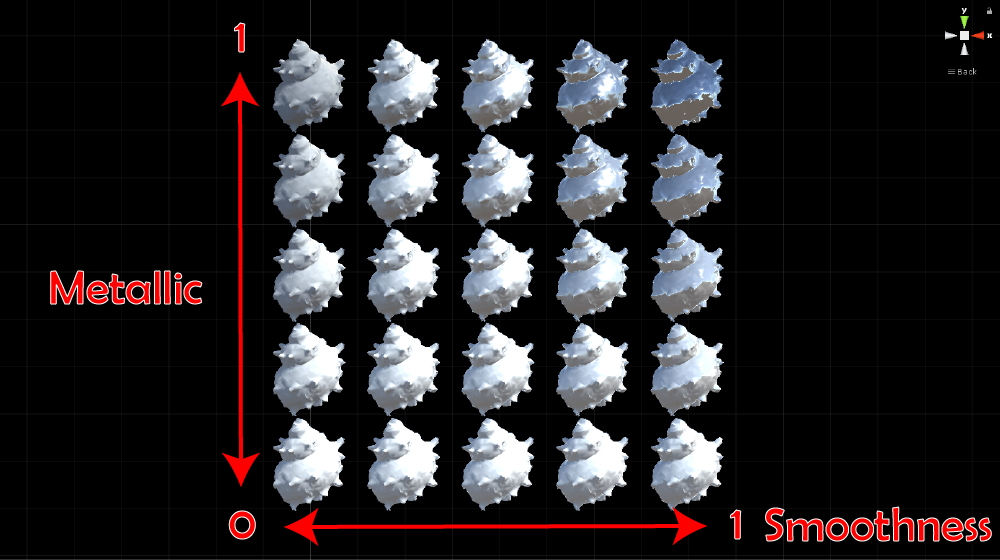
‘Metallic’ and ‘Smoothness’
Use Unity’s Unlit Shader
Unlit Shader is a shader that doesn’t reflect any light. Since it is not affected by any lights, the object doesn’t cast any shadow.
Unlit Shader
It’s useful to keep the object unaffected by lights or make it look ‘less 3D’ on purpose. It’s also suitable for the 3D model created by photogrammetry. To use ‘Unlit Shader’, open the Inspector of the material and select ‘Unlit > Texture’ from the ‘Shader’ drop-down menu.
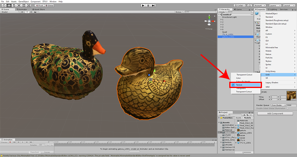
Select ‘Unlit Shader’
Arrange 3D model with a unique shader
From now on, I introduce some ‘unique’ shaders useful when you arrange your 3D model. Create a VR work full of originality by making good use of them.
Wireframe Shader
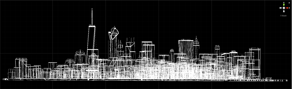
Wireframe Shader
It’s a kind of shaders to display the wireframe only, which is introduced in a website, ‘Shaders Laboratory‘. Although there are some other ‘wireframe’ shaders on the internet, this shader gives a tidier appearance since it has a function to remove diagonal lines of the wireframe.
The code of the wireframe shader
Shader "Custom/Geometry/Wireframe"
{
    Properties
    {
        [PowerSlider(3.0)]
        _WireframeVal ("Wireframe width", Range(0., 0.5)) = 0.05
        _FrontColor ("Front color", color) = (1., 1., 1., 1.)
        _BackColor ("Back color", color) = (1., 1., 1., 1.)
        [Toggle] _RemoveDiag("Remove diagonals?", Float) = 0.
    }
    SubShader
    {
        Tags { "Queue"="Geometry" "RenderType"="Opaque" }

        Pass
        {
            Cull Front
            CGPROGRAM
            #pragma vertex vert
            #pragma fragment frag
            #pragma geometry geom

            // Change "shader_feature" with "pragma_compile" if you want set this keyword from c# code
            #pragma shader_feature __ _REMOVEDIAG_ON

            #include "UnityCG.cginc"

            struct v2g {
                float4 worldPos : SV_POSITION;
            };

            struct g2f {
                float4 pos : SV_POSITION;
                float3 bary : TEXCOORD0;
            };

            v2g vert(appdata_base v) {
                v2g o;
                o.worldPos = mul(unity_ObjectToWorld, v.vertex);
                return o;
            }

            [maxvertexcount(3)]
            void geom(triangle v2g IN[3], inout TriangleStream triStream) {
                float3 param = float3(0., 0., 0.);

                #if _REMOVEDIAG_ON
                float EdgeA = length(IN[0].worldPos - IN[1].worldPos);
                float EdgeB = length(IN[1].worldPos - IN[2].worldPos);
                float EdgeC = length(IN[2].worldPos - IN[0].worldPos);

                if(EdgeA > EdgeB && EdgeA > EdgeC)
                    param.y = 1.;
                else if (EdgeB > EdgeC && EdgeB > EdgeA)
                    param.x = 1.;
                else
                    param.z = 1.;
                #endif

                g2f o;
                o.pos = mul(UNITY_MATRIX_VP, IN[0].worldPos);
                o.bary = float3(1., 0., 0.) + param;
                triStream.Append(o);
                o.pos = mul(UNITY_MATRIX_VP, IN[1].worldPos);
                o.bary = float3(0., 0., 1.) + param;
                triStream.Append(o);
                o.pos = mul(UNITY_MATRIX_VP, IN[2].worldPos);
                o.bary = float3(0., 1., 0.) + param;
                triStream.Append(o);
            }

            float _WireframeVal;
            fixed4 _BackColor;

            fixed4 frag(g2f i) : SV_Target {
            if(!any(bool3(i.bary.x < _WireframeVal, i.bary.y < _WireframeVal, i.bary.z < _WireframeVal)))
                 discard;

                return _BackColor;
            }

            ENDCG
        }

        Pass
        {
            Cull Back
            CGPROGRAM
            #pragma vertex vert
            #pragma fragment frag
            #pragma geometry geom

            // Change "shader_feature" with "pragma_compile" if you want set this keyword from c# code
            #pragma shader_feature __ _REMOVEDIAG_ON

            #include "UnityCG.cginc"

            struct v2g {
                float4 worldPos : SV_POSITION;
            };

            struct g2f {
                float4 pos : SV_POSITION;
                float3 bary : TEXCOORD0;
            };

            v2g vert(appdata_base v) {
                v2g o;
                o.worldPos = mul(unity_ObjectToWorld, v.vertex);
                return o;
            }

            [maxvertexcount(3)]
            void geom(triangle v2g IN[3], inout TriangleStream triStream) {
                float3 param = float3(0., 0., 0.);

                #if _REMOVEDIAG_ON
                float EdgeA = length(IN[0].worldPos - IN[1].worldPos);
                float EdgeB = length(IN[1].worldPos - IN[2].worldPos);
                float EdgeC = length(IN[2].worldPos - IN[0].worldPos);

                if(EdgeA > EdgeB && EdgeA > EdgeC)
                    param.y = 1.;
                else if (EdgeB > EdgeC && EdgeB > EdgeA)
                    param.x = 1.;
                else
                    param.z = 1.;
                #endif

                g2f o;
                o.pos = mul(UNITY_MATRIX_VP, IN[0].worldPos);
                o.bary = float3(1., 0., 0.) + param;
                triStream.Append(o);
                o.pos = mul(UNITY_MATRIX_VP, IN[1].worldPos);
                o.bary = float3(0., 0., 1.) + param;
                triStream.Append(o);
                o.pos = mul(UNITY_MATRIX_VP, IN[2].worldPos);
                o.bary = float3(0., 1., 0.) + param;
                triStream.Append(o);
            }

            float _WireframeVal;
            fixed4 _FrontColor;

            fixed4 frag(g2f i) : SV_Target {
            if(!any(bool3(i.bary.x <= _WireframeVal, i.bary.y <= _WireframeVal, i.bary.z <= _WireframeVal)))
                 discard;

                return _FrontColor;
            }

            ENDCG
        }
    }
}
How to use it
① Create a new shader in the Project window and double-click it to open its code. Copy and paste the code shown above into it. ② Create a material and attach it to the object. Select ‘Custom > Geometry > Wireframe’ from the ‘Shader’ drop-down menu in the Inspector. ③ To delete diagonal lines, check the ‘Remove diagonals ?’ item.
Parameters to adjust
| Parameter | Description | How to set |
| Wireframe width | The width of wireframe | Set it to the value between 0 and 0.5. |
| Front colour | The colour of the wireframe rendering the front side of the surface. | Set the colour you want by the colour dialogue window. |
| Back colour | The colour of the wireframe rendering the back side of the surface. | Set the colour you want by the colour dialogue window. |
| Remove diagonals? | It switches the visibility of diagonal lines. | Check it to delete diagonal lines. |
Gem Shader
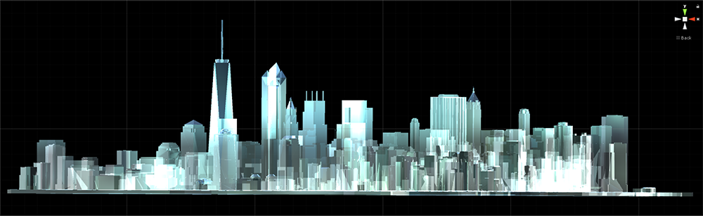
Gem Shader
Gem Shader is a free shader available in Unity Asset Store, which gives a glittering appearance like a jewel to 3D model.
How to use it
① Access the page of ‘Gem Shader‘ in Unity Asset Store, and click the ‘import’ button to import the asset. ② In the project window, open ‘Gem > Material’ to find the material. Attach it to the object.
Parameters to adjust
| Parameter | Description | How to set |
| color | The colour of ‘Gem’ | Set the colour you want by the colour dialogue window. |
| Reflection Strength | How strongly it reflects lights | |
| Environment Light | How much it’s affected by ambient light | |
| Emission | The intensity of the light emission from the surface | The larger value makes it look more self-light emitting. |
Minimalist Free
Minimalist Free
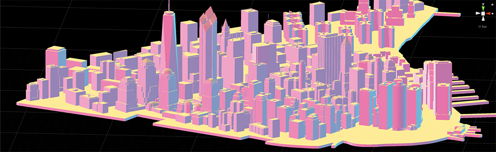
Minimalist Free is a free shader available in Unity Asset Store. It allows you to apply different colours to six different sides (front, back, left, right, top and bottom). It’s is a shader suitable for the object that consists of cubes and cuboids in particular.
How to use it
① Access the page of ‘Minimalist Free‘ in Unity Asset Store, and press ‘import’ button to import the asset. ② Create a material and attach it to the object. Select ‘Minimalist free > Standard’ from the ‘Shader’ drop-down menu in the Inspector. ③ Adjust the parameters as you like.
Parameters to adjust
| Parameter | Description | How to set |
| Main Texture | The texture to apply to the faces | You can specify the texture. |
| Custom Shading/Front | The colour of the front face | Once you set ‘Shading Mode’ to ‘Solid Color’, you can specify the colour by the colour dialogue window. The free version doesn’t support the gradation function. |
| Custom Shading/Back | The colour of the back face | |
| Custom Shading/Left | The colour of the left face | |
| Custom Shading/Right | The colour of the right face | |
| Custom Shading/Top | The colour of the top face | |
| Custom Shading/Down | The colour of the bottom face |
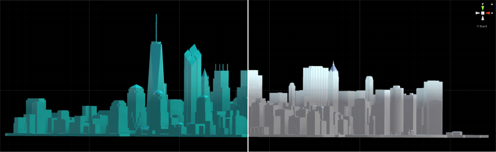
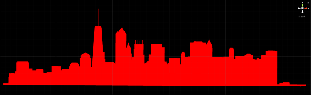
Colour By Height Shader
Colour By Height
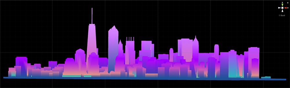
‘Colour By Height Shader’ is a free shader available in Unity Asset Store, which applies the gradation in the vertical direction to a 3D model.
How to use it
① Acess the page of ‘Colour By Height Shader‘ in Unity Asset Store, and press the ‘import’ button to import the asset. ② Create a material and attach it to the object. Select ‘Unlit > Colour By Height’ from the ‘Shader’ drop-down menu in the Inspector. (There is also the ‘Lit’ version, which is affected by ambient light. To use it, Select ‘Lit > Flat Shaded Colour By Height’. ③ Adjust the parameters as you like.
Parameters to adjust
| Parameter | Description | How to set |
| Highest Point/~Highest | The height where the colour starts changing. | The gradation of more than two colours doesn’t work in many cases. I am not sure it’s a bug or an expected behaviour by the developer. |
| ~Colour | The colour for each height |
Import to STYLY
It’s very easy to import the object attached a shader to into STYLY. All you need it to convert the created object to a Prefab and upload it to STYLY. The article below explains how to upload an asset from Unity to STYLY in detail. Read the article The appearance of a 3D model changes dramatically by using shaders. There are a lot of interesting shaders, so please find your favourite shader.