Introduction
This series is for beginners with little to no experience in modeling. We will go over the basics of Blender, create a simple 3D model, and upload it to STYLY.
In the Previous Article
If you are completely new to Blender, read this article to get familiar with the interface.
![[Blender for Beginners] Let’s start Modeling Part 1 – Downloading Blender & Navigating the Interface](https://styly.cc/wp-content/uploads/2019/09/image1-160x160.png)
In the first article of the series, we created a simple model by moving and scaling the default cube.
In the second and third articles, we will look into more complicated modeling techniques.
What We Will Create
Here is the model that we will be creating in the second and third articles:
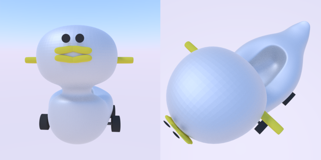
The Finished Result
It’s a duckling potty with tires! We will build this over two articles.
Basics of Modeling
Edit Mode and Object Mode
After opening Blender, select the default cube and press [Tab].
With this, the cube’s appearance (the way it is selected) will change, like in the image below:
![[Tab]キーで切り替え](https://styly.cc/wp-content/uploads/2020/08/Untitled-1-1.png)
Press Tab to switch between Object Modes.
The left image is in Object Mode, and the right side is in Edit Mode.
In Object Mode, objects can be scaled and moved as they are.
In Edit Mode, you can modify the vertices, edges, and faces of the object.
Most of the time, you will create shapes by tweaking these vertices, edges, and faces in Edit Mode.
You can switch between Object Mode and Edit Mode by pressing [Tab] or from the menu bar at the top of the window.
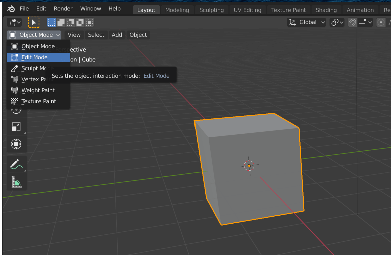
Switching Object Modes from the menu bar.
There are many shortcut keys to learn in Blender, but once you know them, modeling will become much faster. Remember to use the [Tab] key to switch between Object Modes.
Using Extrude
In this article, we will practice extruding, which is a basic way to edit your mesh in Edit Mode.
In Edit Mode, you will see three icons on the menu bar. They are, from left to right, vertices, edges, and faces.
In the next example, we will choose faces, the third icon from the left.
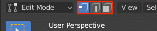
Edit Mode in the menu bar.
Also, make sure that the Move tool is selected.
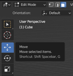
Move Tool
Now, by clicking anywhere on the cube, you should be able to select a face.
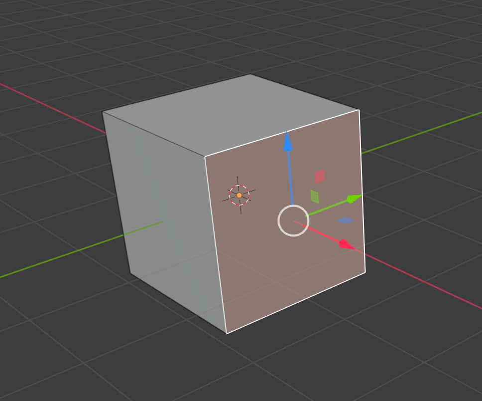
Selecting a Face of the Cube
First, try moving the red arrow on the x-axis. The cube should extend in that direction.
Next, press [E] and move the face on the x-axis. This time, the cube should have extended in the same direction, but with another cube joined to the original one.
Go back to the default cube, select the same face, and increase the scale by pressing [S]. Only the selected face should be scaled.
Now, press [E] then [S], and move the mouse to scale it down. A smaller face will be created within the face.
Press [E] again and move the face on the x-axis, and repeat the process to create differently sized shapes.
Practice Using Extrude
This process of adding vertices, edges and faces by pushing them out is called extruding.
Extruding and scaling or moving these new faces to create various shapes is a basic technique in modeling.
Vertices and edges can be extruded and moved in the same way as faces.
Next, let’s press [Tab] to go back into Object Mode.
Notice that all the new faces that you have just created with extrusion are one object.
Press [X] to delete what you have just created, as this was only an object for practicing extrusion.
Modeling the Duck Potty
Modeling the Body
Now, let’s start modeling our main object – the duck potty.
To add a new cube, select Add>Mesh>Cube in the menu bar or press [Shift]+[A] to bring up the same menu.
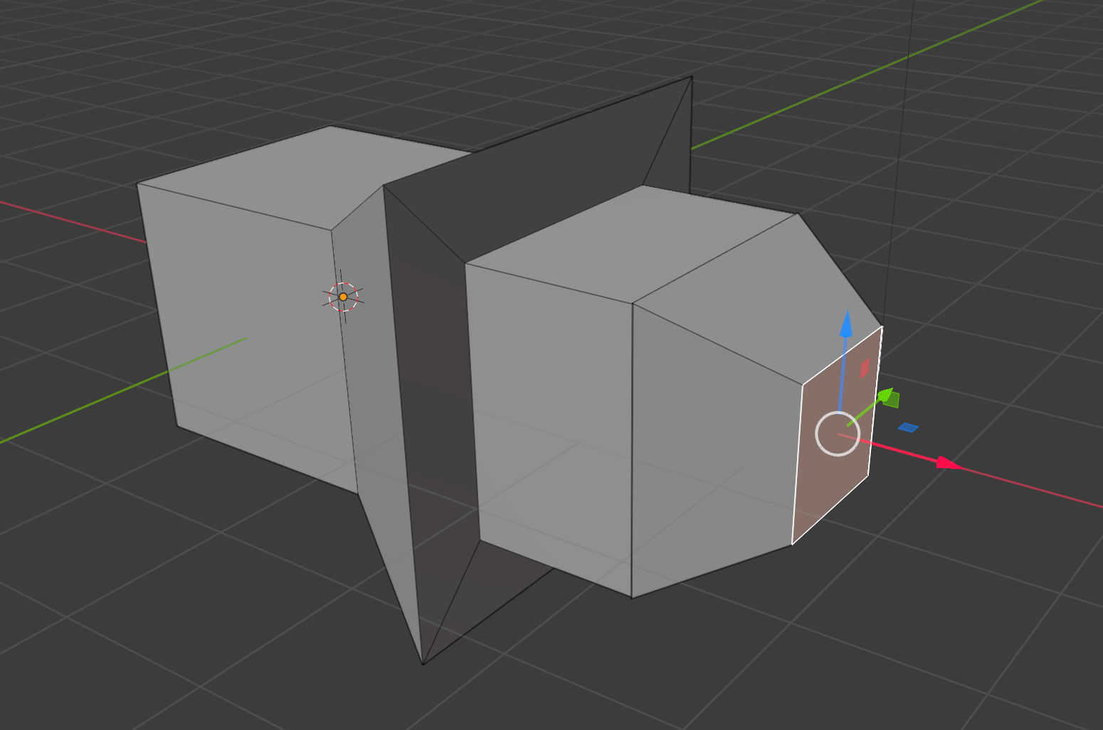
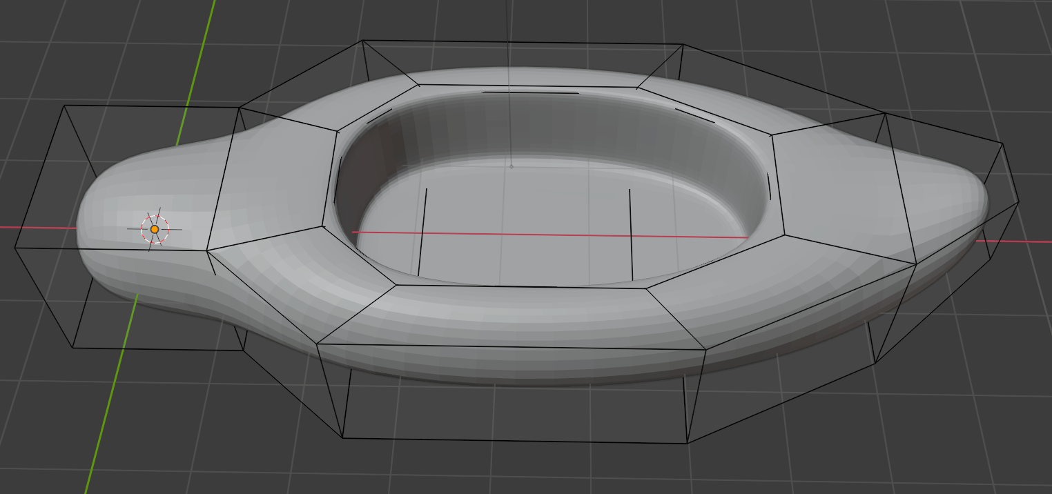
Switch to Edit Mode by pressing [Tab]. Using what we learned above, use extrude to make it look like the two pictures below.
As in Object Mode, you can scale the object on the x-axis with [S] [X] in Edit mode.
So, if you want to scale the object on the x-axis after extruding a face, press [E] [S] [X] and then move the mouse to adjust the face to the desired size.

Top View

Diagonal View
Here are some basic instructions on creating the base of your duck potty model:
- Extrude the face of the cube and move it out slightly on the x-axis, then increase the scale slightly on the y-axis.
- Extrude the same face and move it out on the x-axis.
- Extrude the same face again, move it out on the x-axis and then scale it down on the y-axis.
- Extrude the same face again, move it out on the x-axis, scale it down on the y and z-axis, and then move it slightly on the z-axis.
Before creating a hole in the duck potty, open the Modifiers tab (the wrench icon) in the Properties menu. Click Add Modifier and choose Subdivision Surface.

Clicking the wrench icon will open the Modifier Settings.
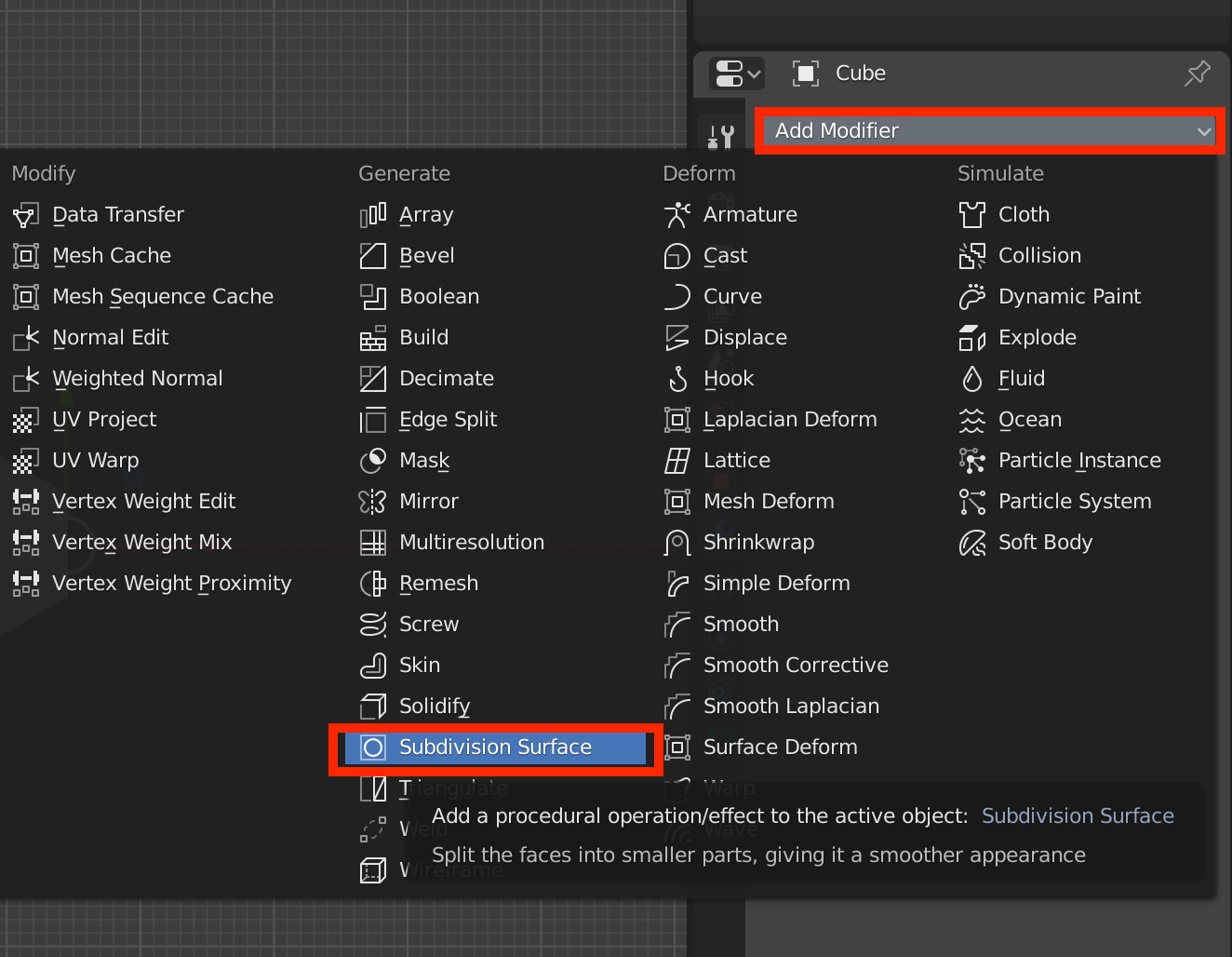
Select Subdivision Surface
When you select Subdivision Surface, the body of the duck becomes rounded.
How “round” the model looks is determined by the Levels Viewport in the Subdivision Surface settings. However, keep in mind that the higher the number, the more polygons are created. We recommend stopping at a maximum of 3 or 4 to prevent Blender from crashing.
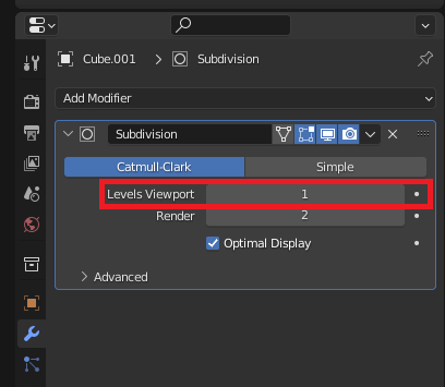
Adjust the levels of your subdivision here.
Modifiers are convenient because you can adjust the levels of subdivision without applying them to your mesh.
To see this, set the Levels Viewport to 3 and switch to Edit Mode. Since we have not applied the subdivision, the vertices, edges, and faces are editable as they are.
Now, hold down [Shift] and select these three faces:
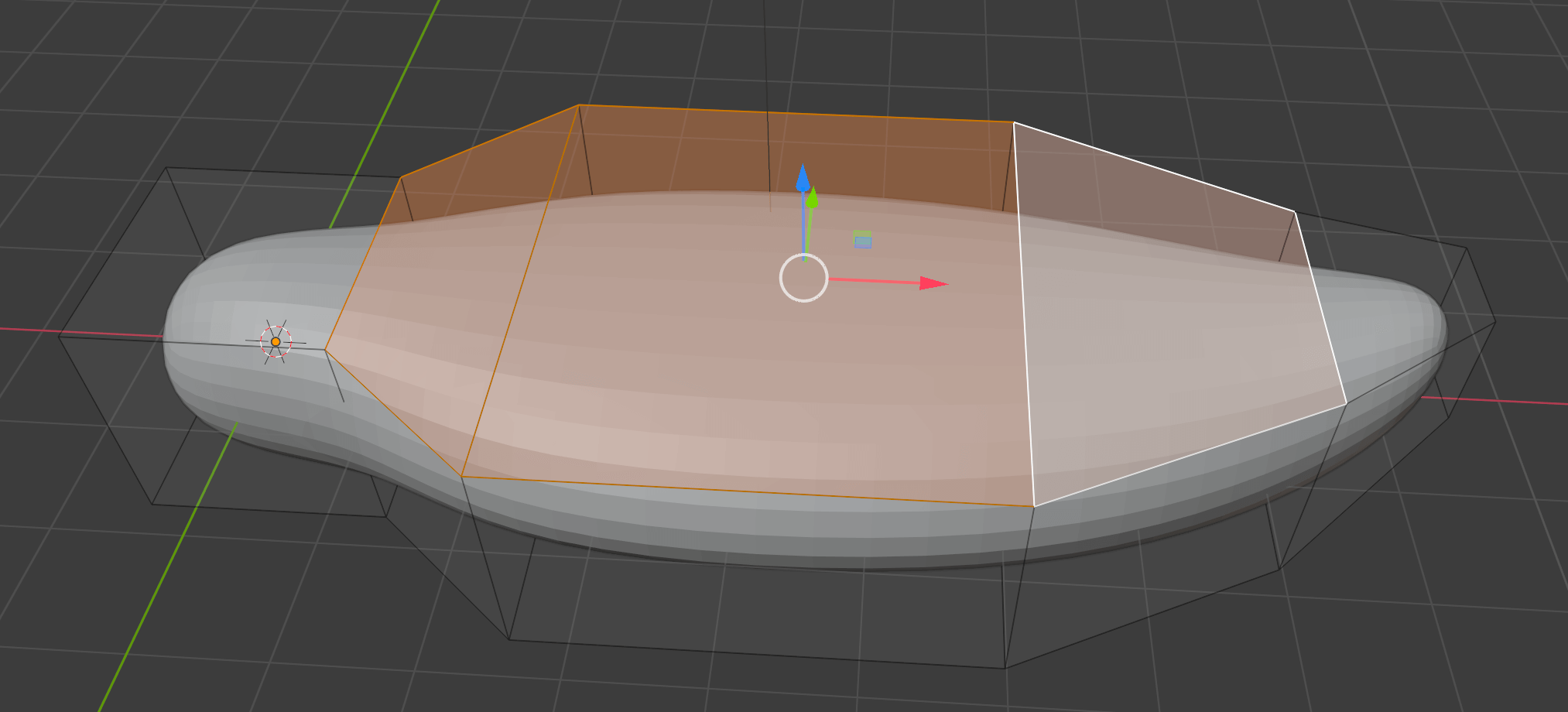
Selecting the Three Faces
Scale down the three faces with [E] + [S], then press [E] and move down on the z-axis to make a hole in the potty.
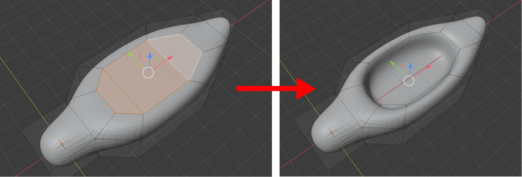
Creating a Hole in the Potty
By the way, the above process of selecting multiple faces and resizing them with [E] + [S] can also be done by simply pressing [I], which is the shortcut to Inset Faces.
However, with Inset Faces, you cannot scale on a single axis, such as the x-axis.
Right now, the edges of the hole are too smooth, so let’s make them a little sharper. This is easily done by disabling the Subdivision Surface, so let’s set the Levels Viewport to 0.
Then, from the three icons in menu bar, click Edges and select the edges of the hole.
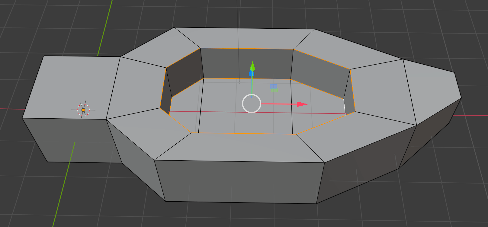
Selecting the Edges
To select an edge end-to-end, hold down [Alt] and select one of the edges. This is called Selecting an Edge Loop. This can also be applied to vertices and faces.
Once the two edge loops shown above are selected, select Bevel Edges from the menu that appears by pressing [Ctrl]+[E] and move the mouse to bevel the corners. It should look like the image below:
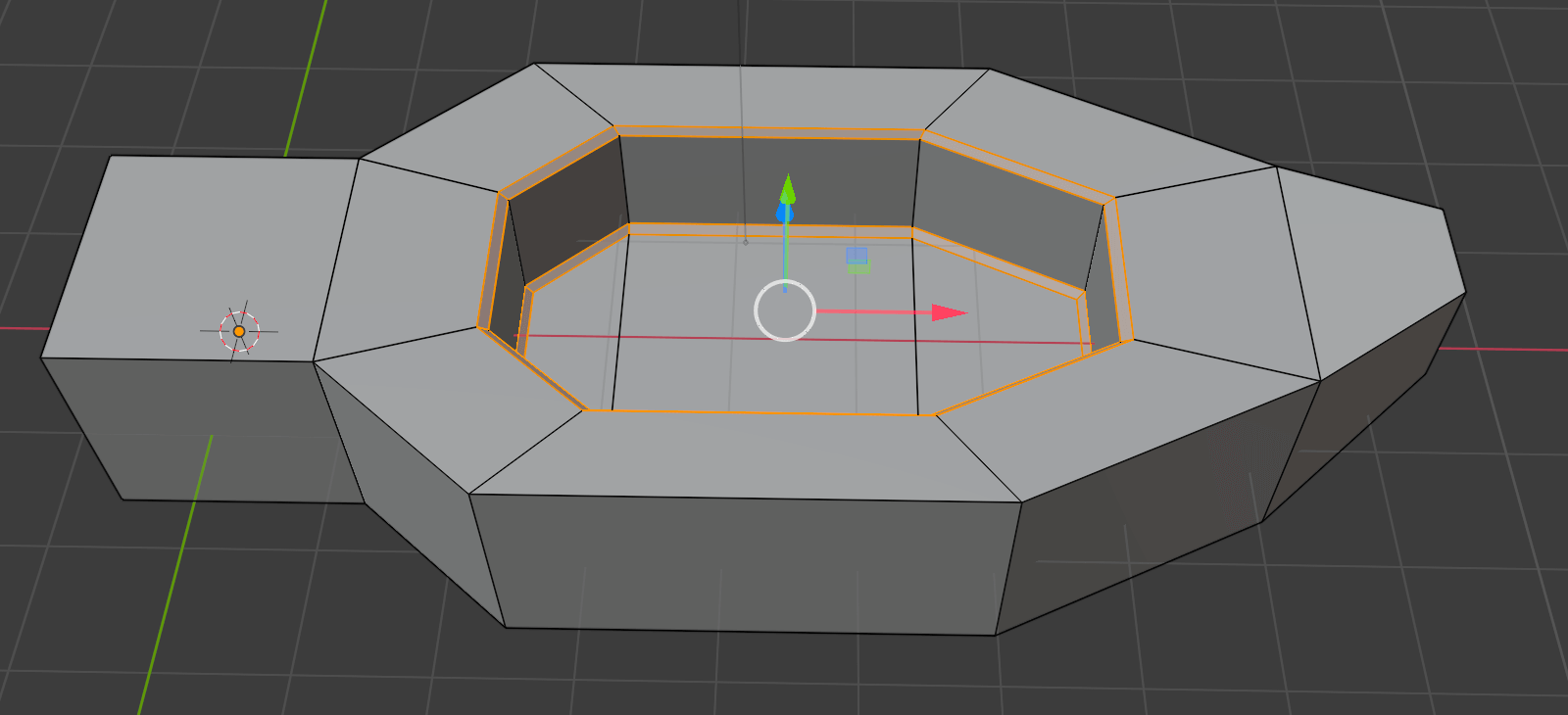
Bevel
After you have finished beveling, put the Subdivision Surface Level Viewport back to 3. The hole’s edges should be sharper than before.
The edge of the hole is now sharp.
The edges have turned out round due to the way Subdivision Surface works – the further the vertices, the rounder the edge; the closer the vertices, the sharper the edge.
Bevel is used usually to drop corners but can also be used to create edges closer to each other without changing the overall shape of an object.
Sometimes it is difficult to see the final outcome in Edit Mode, so we recommend occasionally switching to Object Mode to preview what your model looks like with the modifiers applied.
We actually used Bevel in the previous article by adding it as a Modifier. When we use the Bevel Modifier, the bevel is applied to the entire object. When we select and bevel edges in Edit Mode, we only bevel the edges that we select.
Modeling the Head
We are almost finished! Finally, let’s model the head.
From the icons in the menu bar, switch to face selection.
Select the face below, and extrude this to create the shape of the head.
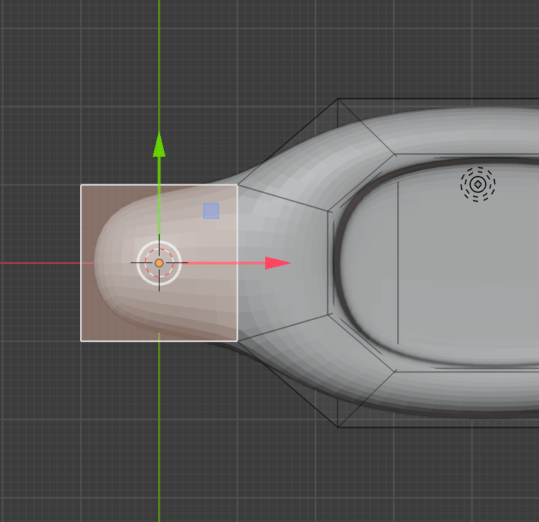
We will model the head by extruding this face.
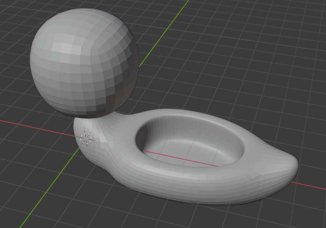
The finished result looks like this – use this as a reference while using Extrude to create your head:

The finished model of the head.
Zoom out and make sure to inspect the entire model. Refine the edges and faces to your liking.
Refining the Shape
That’s all for now!
Do not press Apply for the Subdivision Surface yet, as we will be modeling the eyes and mouth and adding color to our duck potty in the next article.
Vocabulary and Shortcut Keys to Remember from this Article
Vocabulary
- Object Mode: Allows editing position, rotation and scale, and so on.
- Edit Mode: A mode for editing an object’s vertices, edges, and faces.
- Extrude: Duplicates faces and pushes them out while keeping the new geometry connected with the original vertices.
- Modifier: An operation that affects an object’s geometry in a non-destructive way. It can be added by clicking the wrench icon in the tab on the right of the Properties editor.
- Subdivision Surface: A type of modifier that is used to split the faces of a mesh into smaller faces, giving it a smooth appearance.
- Inset Faces: Takes the currently selected faces and creates an inset of them.
- Bevel: Smooths out edges and corners.
Shortcut Keys
- [Tab]: Switch between Object Mode and Edit Mode.
- [E]: Extrude.
- [E] [S]: Extrude and scale. Press [X], [Y], or [Z] to scale on that axis.
- [I]: Inset Faces. The same as [E] [S].
- Holding [Alt] while selecting an edge: Selects a loop of edges that are connected in a line end-to-end, passing through the edge under the mouse pointer. Holding [Shift]+[Alt] while clicking adds to the current selection.
- [Ctrl]+[E]: Displays a menu for edges in Edit Mode.
Read the next article here:
For questions about STYLY, bug reports, and improvement requests, please contact the STYLY FORUM
https://en.forum.styly.cc/support/discussions
Certified (QA) by Shota Shawn Yoshizawa
Edited by SASAnishiki
Translated by cpnnn