A
“3D scan model” is a 3D model generated from a real object using a LiDAR scanning application, etc. While the ease with which a model can be generated using only a smartphone is popular, there are cases where the scan may not be clean or the file size is too large to handle
. This
article outlines how to correct such cases
.
What is 3D scan model modification?
3D scan models easily reproduce real space, but the automatically generated models are not always as intended, for example, the data is heavy, or you want to modify the model’s aperture or shape.
In
such cases, it is necessary to modify the scanned model.
This article will introduce methods to reduce the weight of heavy data, to close apertures in the scan, to smooth unevenness to make it natural, and to adjust complex shapes that were not generated during scanning based on actual cases
.
The following is a comparison and usage of various 3D scanning applications.
![[iPad / iPhone Pro Series] LiDAR 3D Scanning App Article Summary](https://styly.cc/wp-content/uploads/2021/12/eyecatch-1-160x160.png)
This article does not explain Blender or STYLY Studio or introductory knowledge on modeling.
unknown
Polygon Reduction
Polygon reduction is a
technique to reduce the weight of a model.
While scanned models are highly reproducible, the data volume of the model tends to be large. In order to run smoothly in STYLY, it is recommended to reduce the weight
.
Polygon reduction is a two-step process.
- Reduce the number of polygons in the model.
- Transfer textures from the original model to the reduced polygon model.
Import the
model into blender
where the model
polygon
count is dropped
.
As an example here, we use a monkey model (aka Suzanne), which is one of Blender’s primitive objects and can be used for testing.
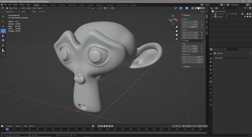
High polygon Suzanne
Turn on wireframe display to see the Edge
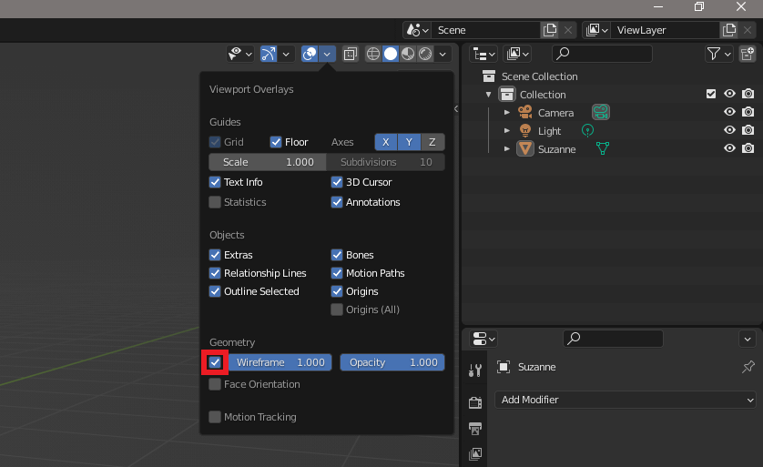
Wireframe Display
Open the Spanner Mark Modifier Properties tab and select Decimate from Add Modifier
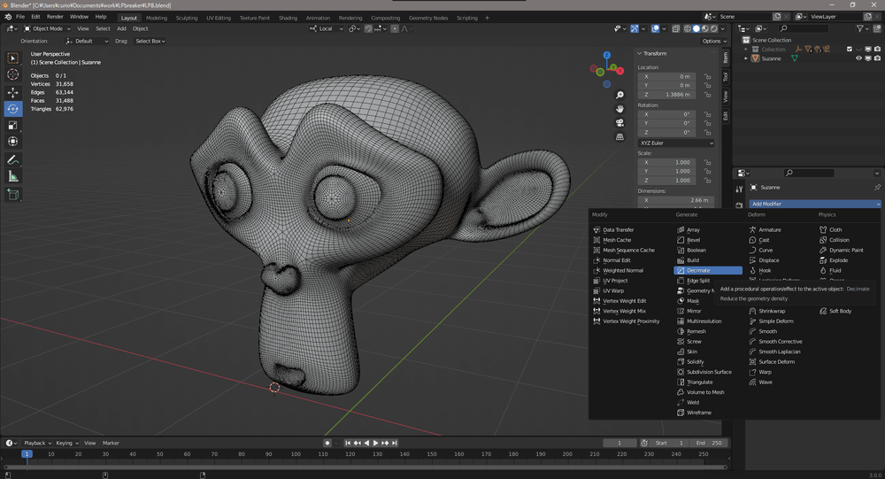
Select Decimate
Enter a numerical value in Ratio to specify the polygon reduction ratio.
At 1.0 there is
no change to the model, and at 0.5 the model has half the polygon count.
The
reduction process starts immediately after entering the numerical value, and the lower the ratio, the greater the processing load.
Reduce the ratio gradually while observing how the shape is destroyed by the reduction.
It is also recommended to enter the numbers directly instead of using mouse drag and drop.
Setting the ratio to 0.1 reduced the polygon count from the original 30,000 to 5,000 polygons.
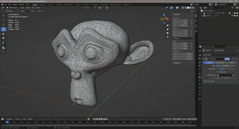
Low Polygon Suzanne
Finally, select Apply from the pull-down to apply
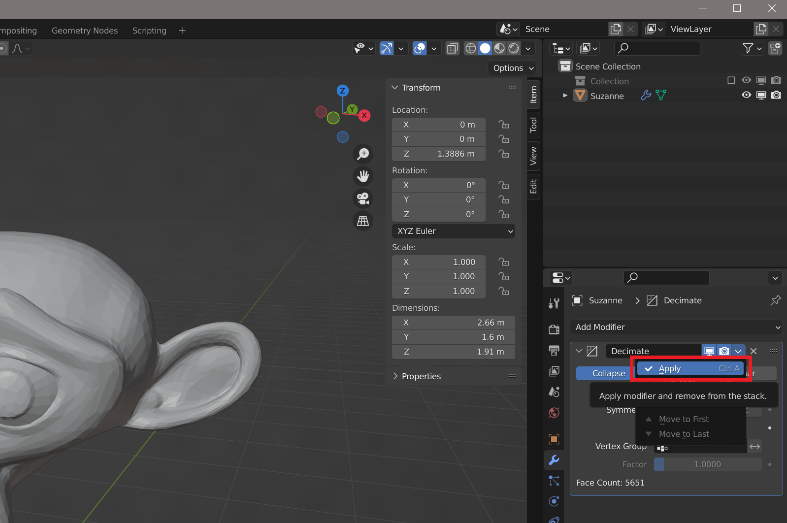
Apply Decimate
Transfer the model’s text
ures The
originally set textures will be visually misaligned because the polygon reduction changed the vertices. The misalignment will be noticeable depending on what is being scanned, so do as needed
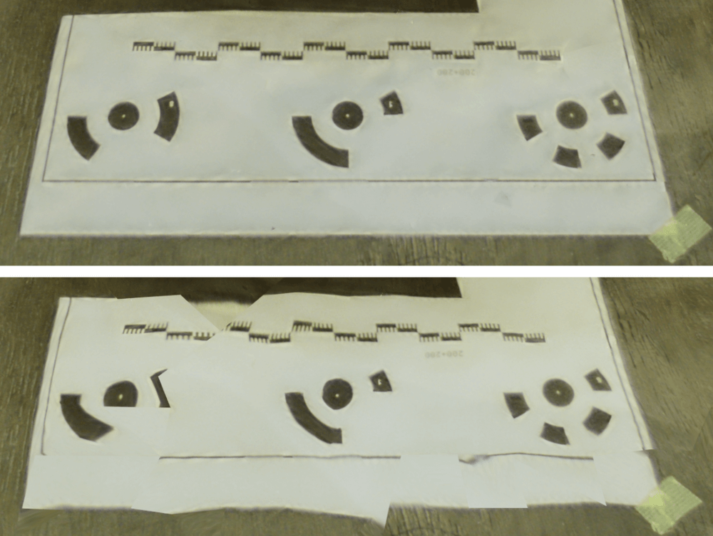
Top: Original, Bottom: Reduction with Decimate 0.01
To
correct the appearance discrepancy, retexture the low-poly model using the model before reduction based on the following article:
![[Blender 2.81] Baking textures into retopology models](https://styly.cc/wp-content/uploads/2020/03/キャプチャ6-160x160.png)
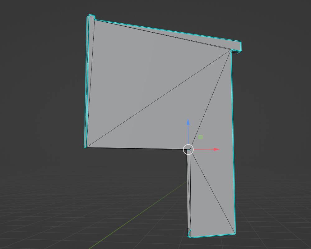
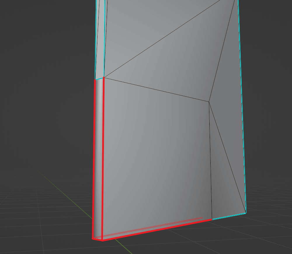
Example 1, Basic, “Blocking Openings”
In
this example, a Mesh is used to seal an opening in a wall
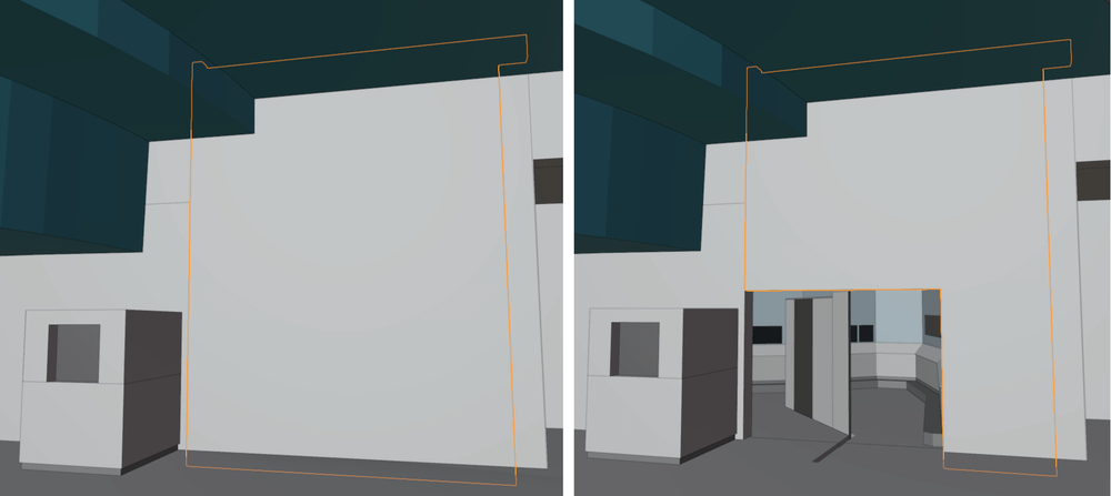
Left after modification, right before
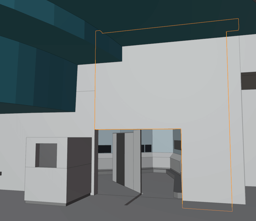
Openings
Individuals are shown individually by selecting the object and pressing the / key
Hide all but the selection
Let’s modify the model using the following technique:
[tab] key to go to Editmode.
Left-click on the red range Mesh to select it and press x key to delete it
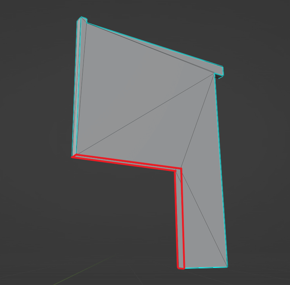
Delete area
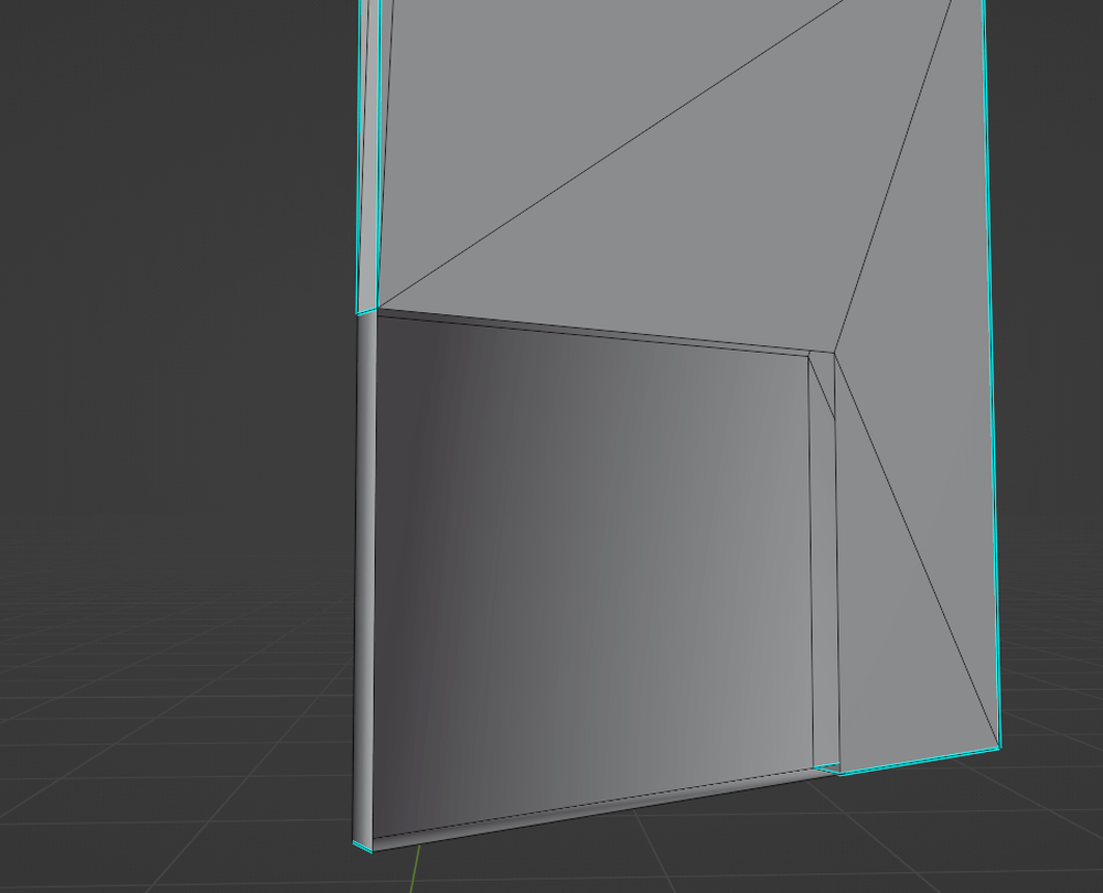
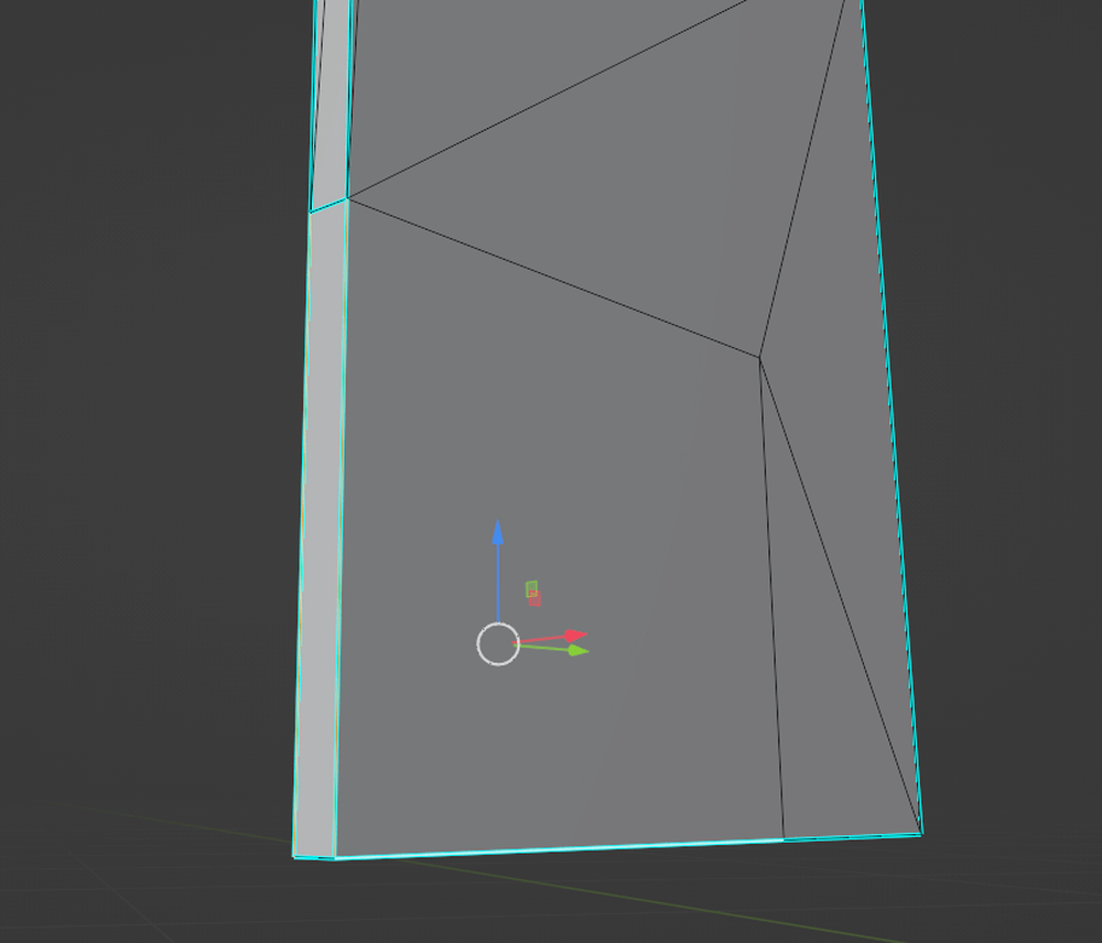
Extend one Edge with the [E] key.
Connect the two remaining Edges with the [F] key to connect the faces

Create a frame with Mesh
Select the four Edges of the opening and close the opening with Mesh using the [F]
key
Stretch the left side with Mesh
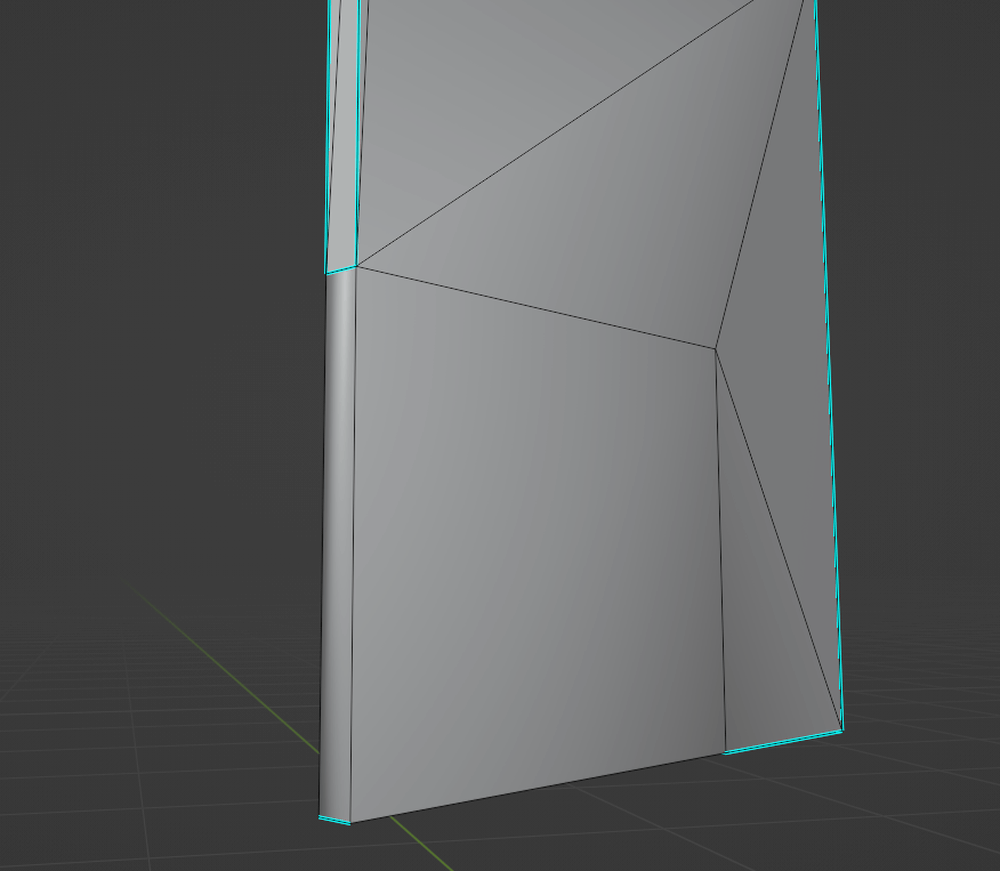
Stretch the right side with Mesh
Adjust the normals.
Select the 5 newly created Edges and click Make Sharp from the right-click menu.
You are now done closing the openings
Edge to Make Sharp
Normal adjustment complete
If you want to assign a texture, do UV expansion.
Go to the UV Editing tab.
Set the right screen to Edit Mode and select the newly created Mesh.
Select UV>Unwrap>Unwrap and do UV expansion.

UV Expansion
Tips: UV Checker
In UV expansion, a UV checker map is temporarily applied to the material to check if the UVs are expanded at the proper ratio.
You can find one on the Internet, or you can create your own at the following site.
UV Checker Map Maker: A site where you can generate UV checker textures in a web browser.
http://uvchecker.byvalle.com/
Example 2: Basic “Adjusting for Unevenness
Sometimes the
surface of a scanned model can be uneven.
In such cases, use Sculpting to even out the surface.
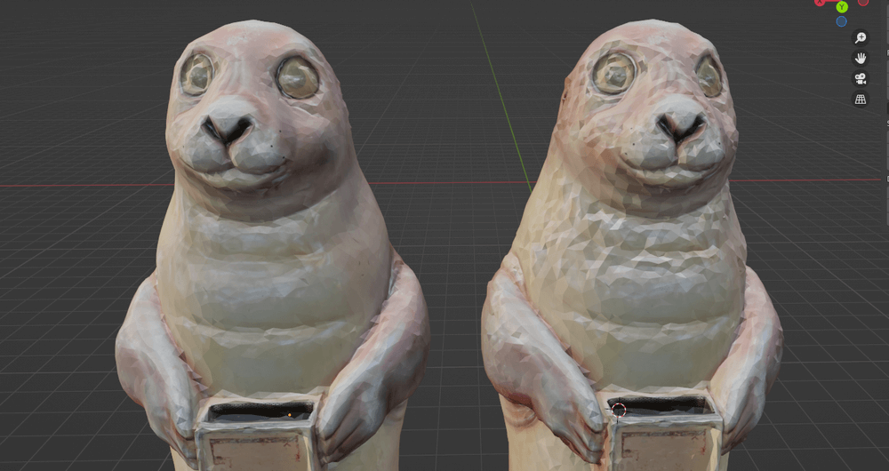
Left: after modification, Right: before modification
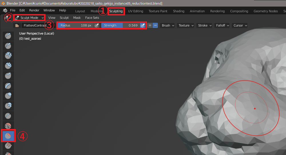
①Click the Sculpting tab to switch workspaces.
②Select “Sculpt Mode” from the mode selection pull-down on the top left button or click the [tab] key to enter Sculpt mode.
③ Adjust the size of the brush with Radius and the strength of the brush effect with Strength.
④Use the Flatten brush and left click to smooth the small surface bumps. just leveling a large surface looks quite different.
Sculpting mode
If you want to adjust fine details, reduce the Radius of the Flatten brush or use other brushes from the brush list on the left side of the screen
.
Example 3 – Application: “Reconstructing a Complex Shape
Delete the areas where the Mesh has failed, paste a new Mesh, and adjust the UVs.
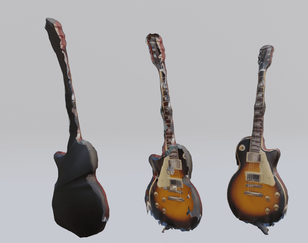
Left: model back after modification, center: model back before modification, right: scanned model front before modification
.
Merging Models
A
scan model may look like a single Mesh, but it may be divided into smaller Mesh pieces.
In such cases, the apertures cannot be selected all at once with alt, so the Mesh is merged together using the following procedure:
Right: scanned model, Left: Mesh placed apart
After selecting all by pressing [A] key, press [M] key and select ByDistance in the menu that appears.
Merge Distance:0.0001 will appear in the lower left corner.
If the shape is not correct, try to adjust this value.
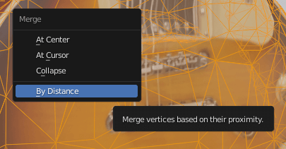
Merge Distance
Mesh Delete
Select the Mesh and [X]key>Face to delete it and [Shift]key+left click in sculpting to smooth the cross section

Mesh deletion
Edge selection
Select>Select All by Trait>Non ManifoldCheck only Boundaries in the lower left checkbox (only in Edge selection mode) or [Alt]key+left click to select boundaries (hold down [Shift]key for additional selection)
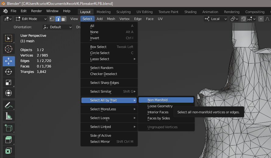
Edge selection with Non Manifold
Mesh creation
[
F]key to fill the currently selected Edge with mesh
Mesh Stitching
Tips: Grid Mesh
If the hole is small enough and the Edge can be adjusted to an even number, it is recommended to use Grid Edge.
Unlike the normal [F] key, it divides the Mesh and makes it easy to adjust the blocked Mesh.
[Ctrl]+[F]keys>Close the hole with Grid Mesh and the grid Mesh.

Create Mesh with Grid Mesh
Tips:
Statistics Display Display Statistics to see how many Edges are selected.
ViewpointOverlays>Statistics checkbox.
The number of Objects, Vertices, Edges, Faces and Trigangles is displayed in the upper left corner.
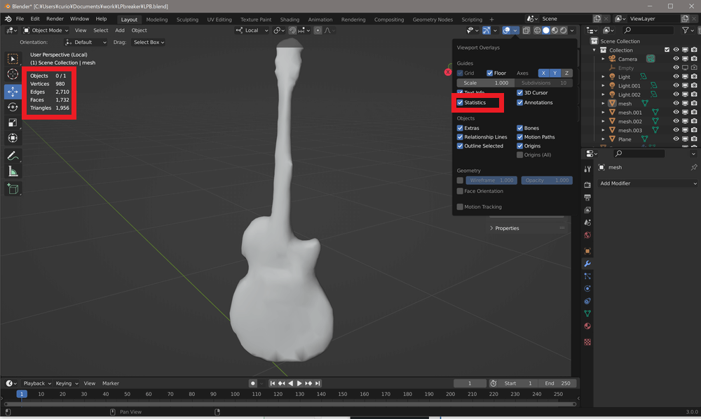
Statistics display
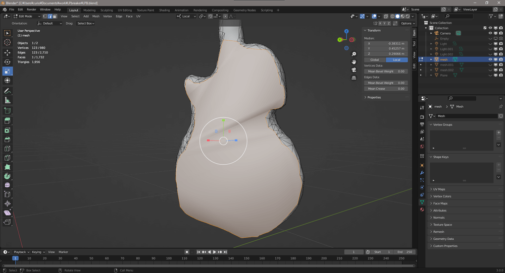
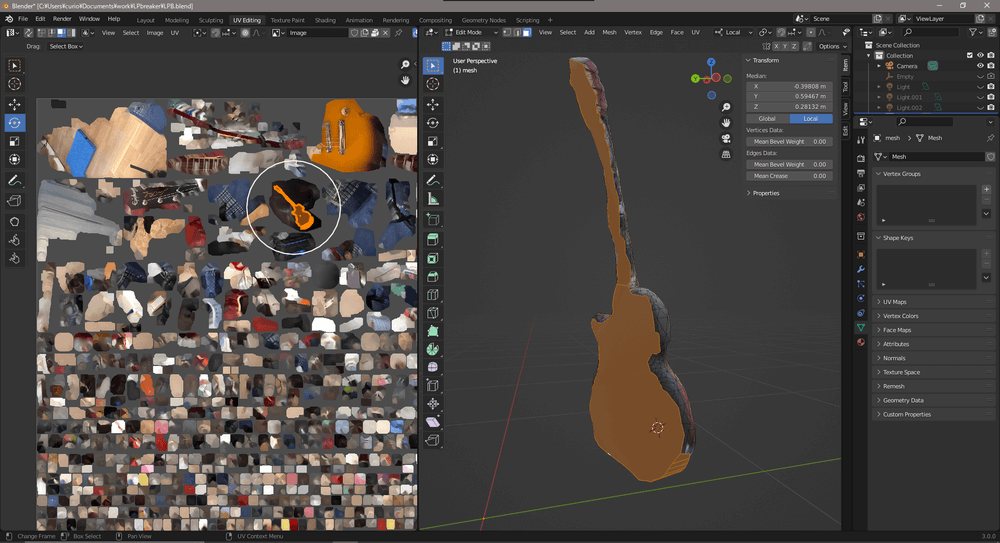
UV development and adjustment
If the
Mesh is just pasted, it will not look right as shown in the image, so the UVs need to be adjusted

The Mesh you created is a mess
Select only the Mesh you created on the right side of the UVEditing tab.
UV>Unwrap>Unwrap and expand the UV.
[
caption id=”attachment_50998″ align=”aligncenter” width=”925″]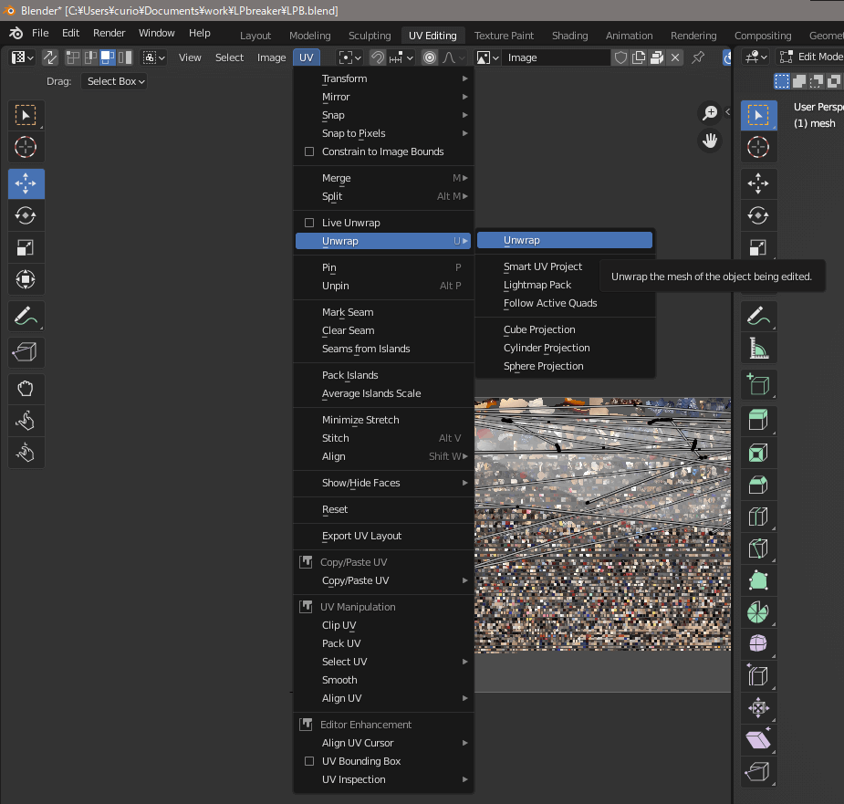 Unwrap[/caption]
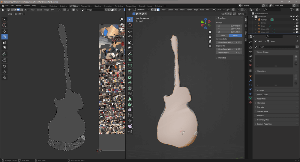
Expanded UV
Place the expanded UV over any color on the UVMAP
Place as desired
.
Upload to STYLY
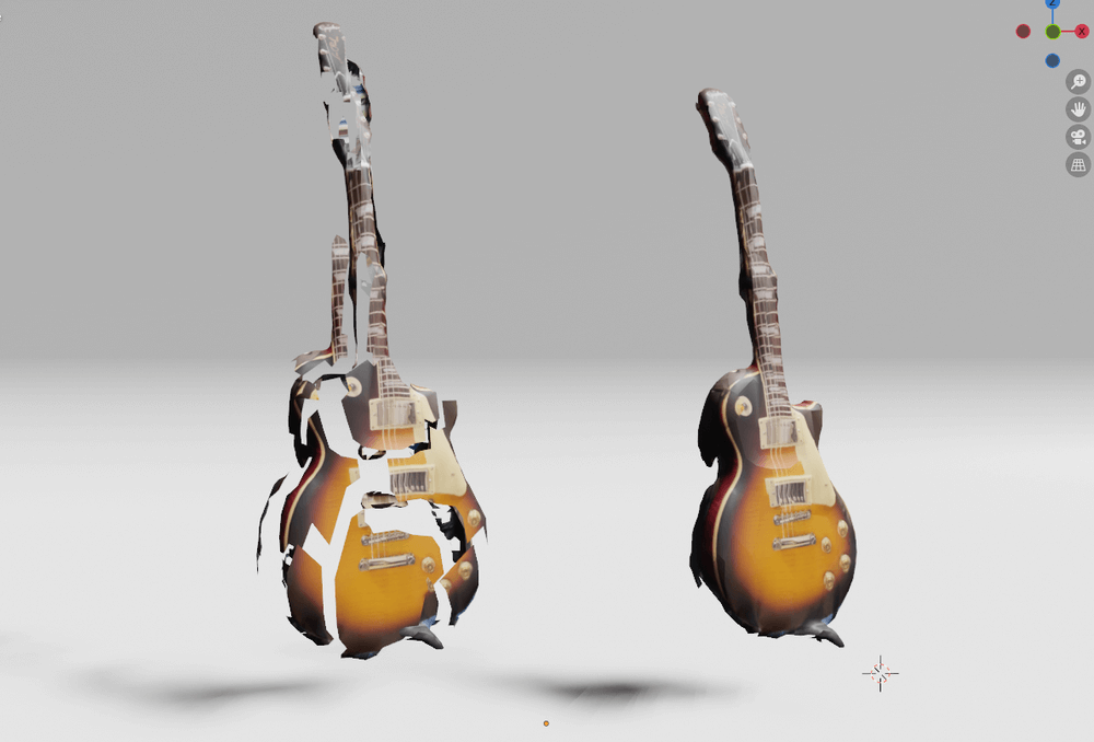
Finally, let’s upload the scan data
to STYLY. The
scene below shows the guitar scan data before and after the modification
.
First, export the data from blender to FBX.
Click File>Export>Fbx
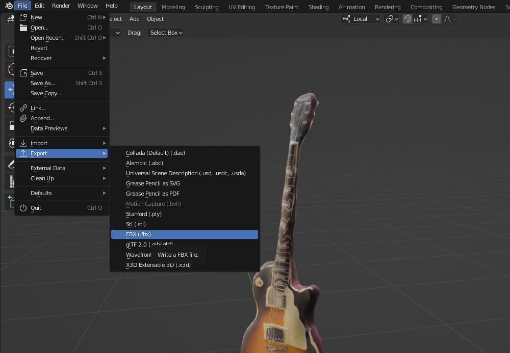
FBX Output
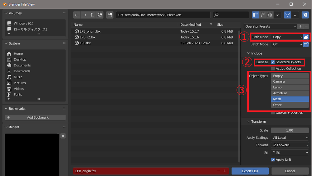
①Select Copy in Path Mode to embed the texture in FBX and click the icon on the far right.
②Check if you want to filter what to output by object type.
③Check as shown in the image as we only need to output mesh data.
Advanced Settings
Next, upload the FBX model to STYLY Studio.
See the “Upload” section of the following article for instructions.
Select the uploaded model and add it to the scene.
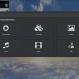
As it is not lit as is, go to Asset button > Environment > Light and select Directional Light, Point Light, Spotlight, etc. as needed and place them in the scene.
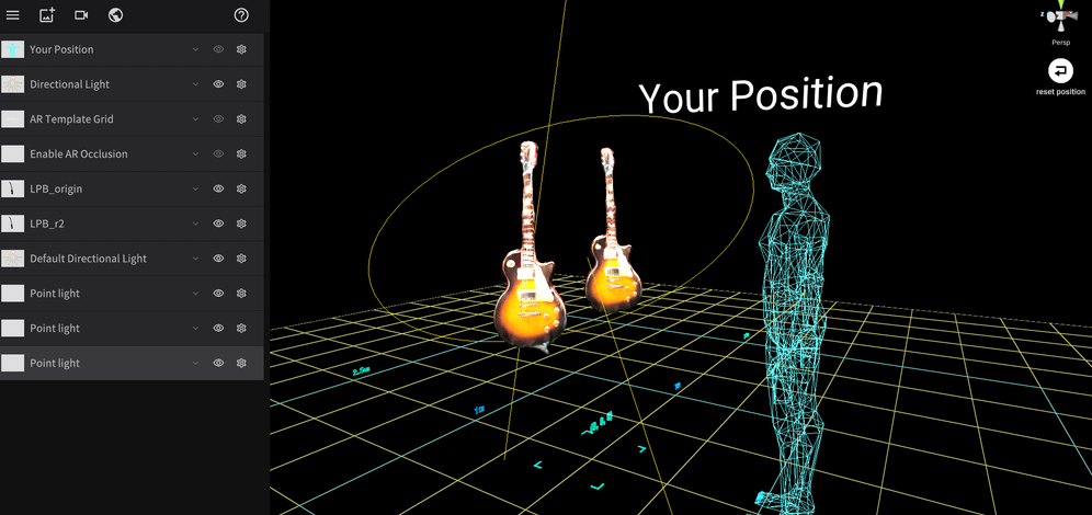
Light placement
Finally, publish the scene from the Publish button
.
Summary
We
have summarized three methods of polygon reduction and modification of scan models.
Scan model creation has become so easy that
even
a
single smartphone can be used to create a scan model.
Even CG beginners can easily incorporate it into scene creation.
Make good use of it to expand your creative range.
Some examples are from the development of VR Keikyu Yubotsubo Marine Park.
Please try viewing VR scenes to find closed phantom rooms and seals.

Questions, bug reports and requests for improvement about STYLY are welcome in the STYLY FORUM
https://jp.forum.styly.cc/support/discussions
Certified (QA) by Shota Yoshizawa
Edited by SASAnishiki