Geometry nodes were introduced in Blender 2.92 as a feature that allows for a wide variety of geometrical expressions.
This article will cover the basics to get you started with geometry nodes.
What Are Geometry Nodes?
Blender’s geometry nodes are a very sophisticated system for modifying the geometry of an object.
With a node-based interface, you can achieve everything from very simple to very complex modifications.
Geometry nodes were introduced in Blender 2.92 but have undergone major changes in version 3.0.
In this article we use Blender 3.2, but many node features are available from Blender 3.0 and later.
Since geometry nodes are relatively new, we expect to see changes and additional features in the future.
Node Characteristics
A node is a method of defining a process by connecting “boxes” with inputs and outputs.
In addition to geometry nodes, Blender has several other node-type interfaces, including shader nodes and compositor nodes.
The elements of nodes are listed below:
| Node | A “box” for data to be processed. |
| Node tree |
The entire structure of multiple connected nodes. |
| Socket | The doorway that defines inputs and outputs to and from a node. Input from the input socket is processed in the node and sent to the output socket. Some nodes have multiple sockets for inputs and outputs. |
Node Types
More than 120 types of nodes are available in the following categories:
| Attribute | Nodes for working with data stored per object element. |
| Color | Nodes for modifying color data. |
| Curve | Nodes that operate only on curves. |
| Curve primitives | Nodes that create a primitive curve, e.g., a circle. |
| Geometry | Nodes that can operate on different geometry types (i.e. volume, mesh). |
| Input | Nodes used mainly as input to other nodes. |
| Instances | Nodes that operate only on instances. |
| Material | Nodes that work with materials. |
| Mesh | Nodes that operate only on meshes. |
| Mesh primitives | Nodes that create a primitive mesh, e.g., a cube. |
| Output | Nodes that output outside the node tree. |
| Point | Nodes that modify the object elements, e.g., vertices. |
| Text | Nodes to manipulate strings. |
| Texture | Nodes to add textures. |
| Utilities | Nodes with general purpose for modifying data. |
| Vector | Nodes for modifying vector quantities. |
| Volume | Nodes for creating or working with volumes. |
In addition to these, there are Group and Layout nodes.
The Geometry Node Workspace
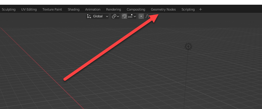
To begin using geometry nodes, click on Geometry Nodes in the Workspace tab at the top of the screen.
Geometry Nodes tab
By default, the geometry nodes workspace looks like this:
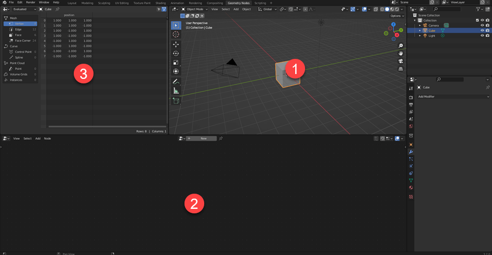
Geometry nodes view
(1) 3D viewport
(2) geometry node editor
(3) spreadsheet
The 3D viewport is the regular 3D view, showing the image in real time.
The geometry node editor is used to connect nodes.
The spreadsheet editor displays data (e.g., vertex positions) for the object selected.
By viewing the spreadsheet, you can ensure that the desired changes are being made to the object.
Connect Nodes
Getting Started
Press the “New” button to start adding nodes.
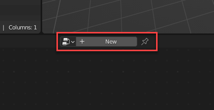
“New” button
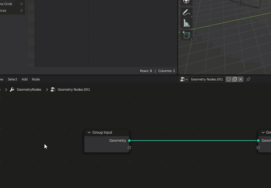
The initial display of the geometry node editor looks like this:
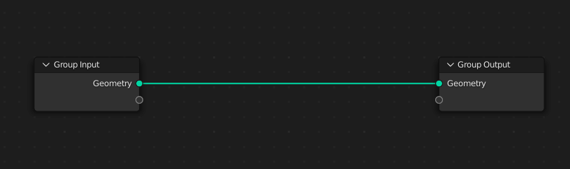
Initial display of the geometry node editor
You can see that the “Group Input” is connected directly to the “Group Output.” There are no modifications to the input; i.e. The output and the input are the same.
Therefore, there will be no changes to the object in the 3D viewport either.
The spreadsheet allows you to see that there are eight vertices, along with their XYZ coordinates.
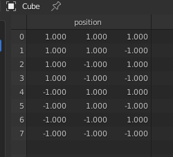
Spreadsheet editor
You can also display different types of data by selecting specific categories (e.g., “Edge” or “Face”) in the left region of the panel.
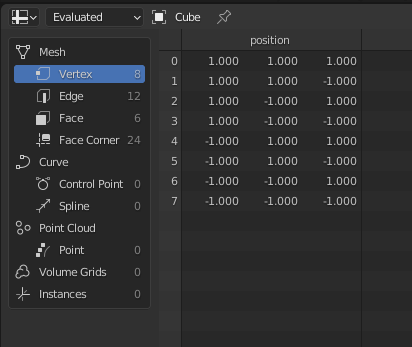
Switching views
Adding Nodes
Let’s add a node by selecting Add > Mesh > Extrude Mesh.
The Extrude Mesh node will appear and you can move it around with your mouse. Move it between the two nodes and left-click when the line turns white.
Adding a new node
With the Extrude Mesh node added, the object’s surfaces are extruded and look like this:
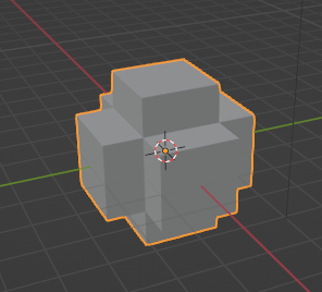
Extruded object
It is possible to change the values of the node. For example, changing the Offset Scale will alter the scale of the extrusion offset.
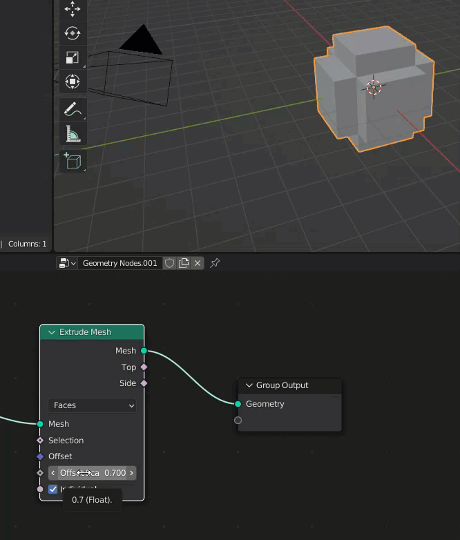
Changing the Offset Scale
By connecting the nodes like this, the geometry data on the left side is processed by the Extrude Mesh node and output as new mesh data.
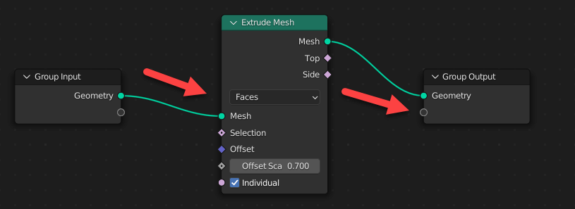
Data flow of geometry nodes
Randomizing the Extrusion
The size of the extrusion can be freely modified like the example above, but it’s also possible to make the extrusion offset random.
To do this, select Add > Utilities > Random Value.
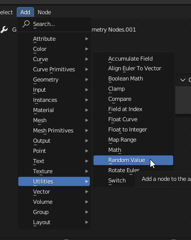
Select the Random Value node
Next, place the node like this:

Adding the Random Value node
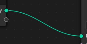
Connect the Value to the Offset Scale.

Connecting the nodes
How to View Node Links
The node link displays several different statuses.
Valid Links
When the link is valid, it is shown as a green line.
Valid link
Invalid Links
When the link is invalid, it is shown as a red line.
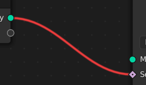
Invalid link
Function Flow Links
When the output data from a node is used as a function for calculations in the next node, it is shown as a dashed line.
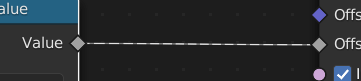
Function flow link
You will see this dashed line appear when the link from the node applies to multiple elements—such as to each face of the object in the example above.
Changing Values Outside the Geometry Node Editor
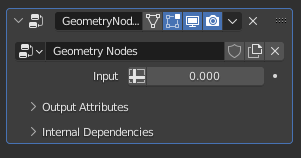
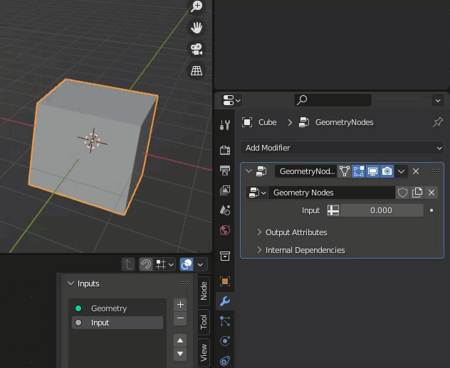
A geometry node can be added to an object as a modifier, so like other modifiers, it can incorporate variables.
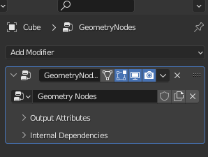
Geometry nodes displayed as a modifier
In the geometry node editor, press the N key to display the panel below.
Select the Group tab of this panel to specify inputs and outputs.

Inputs and outputs
Adding an Input
After adding the input, you will see a new socket added to the node’s Group Input, as shown below.
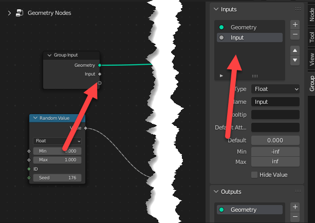
Adding an input
You can now change the value in the modifier properties.
Changing the input value from the Modifier Property tab
Changing this value will affect the geometry.
Behavior when modifier’s input value is changed
Tips to Remember When Exporting to STYLY
As with other modifiers, the geometry nodes modifier must be applied when exporting to STYLY.
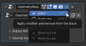
Applying modifiers
You can also automatically apply all modifiers when exporting in formats such as FBX by checking “Apply Transform” before exporting.
Keep in mind that because this is an experimental function, it may not work as expected. If this is the case, make sure to apply the modifiers individually.
In future articles, we will cover applications and other useful ways to use geometry nodes.
Translated by cpnnn