In this article, I will introduce the function and simple usage of Geometry Nodes.
*The version of Blender used in this article is 2.92.
Incidentally, this article is the third in a series of three articles.
In the first article, I introduced the three functions of the Generate modifier (Array/Bevel/Boolean) as an introduction to the modifier tool.
![[Introduction to Blender] Using modifier tools (1) Introduction – Generate(Array/Bevel/Boolean)](https://styly.cc/wp-content/uploads/2021/06/eye-160x160.png)
In the second article, I introduced another three functions of the Generate modifier (Build/Decimate/Edge Split).
![[Introduction to Blender] Using modifier tools (2) Generate (Build/Decimate/Edge Split)](https://styly.cc/wp-content/uploads/2021/06/IMG_9201-160x160.png)
- 1 What is Geometry Nodes?
- 2 Trying to use Geometry Nodes
- 3 Create a motion graphic
- 3.1 Adding a Plane
- 3.2 Adding and Removing Nodes
- 3.3 Assigning a Sphere
- 3.4 Change the size of the Sphere with Attribute Fill
- 3.5 Mixing Attribute Nodes with Attribute Mix
- 3.6 Moving Some Spheres with Vertex Group and Vertex Weight Proximity
- 3.7 Edit the Weight Paint
- 3.8 Adding and editing the Attribute Mix
What is Geometry Nodes?
Geometry Nodes is a function that was added in version 2.92.
As the name implies, you can edit them in node format.
You can use mathematical formulas to create objects that move in a different way than with the existing functions.
Trying to use Geometry Nodes
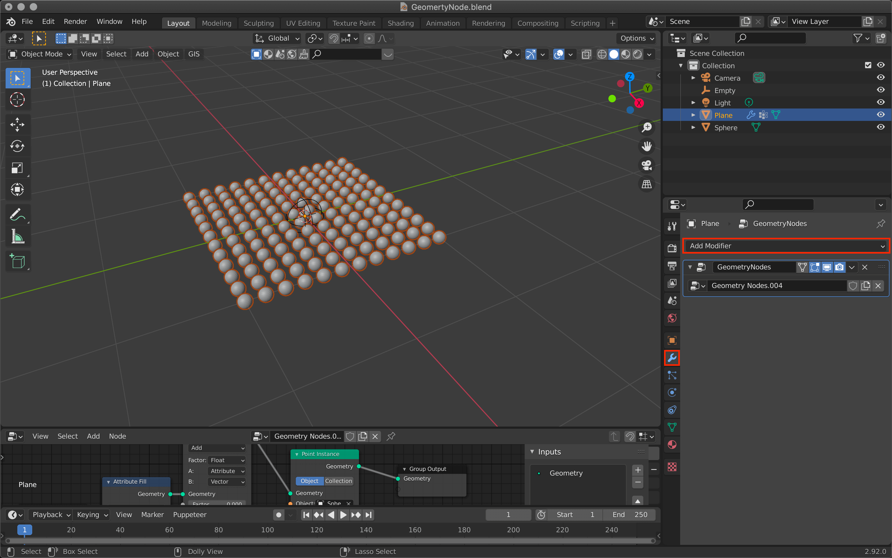
As with other modifier tools, you can add modifiers by clicking on the tool icon.

Tool icon -> Add Modifier
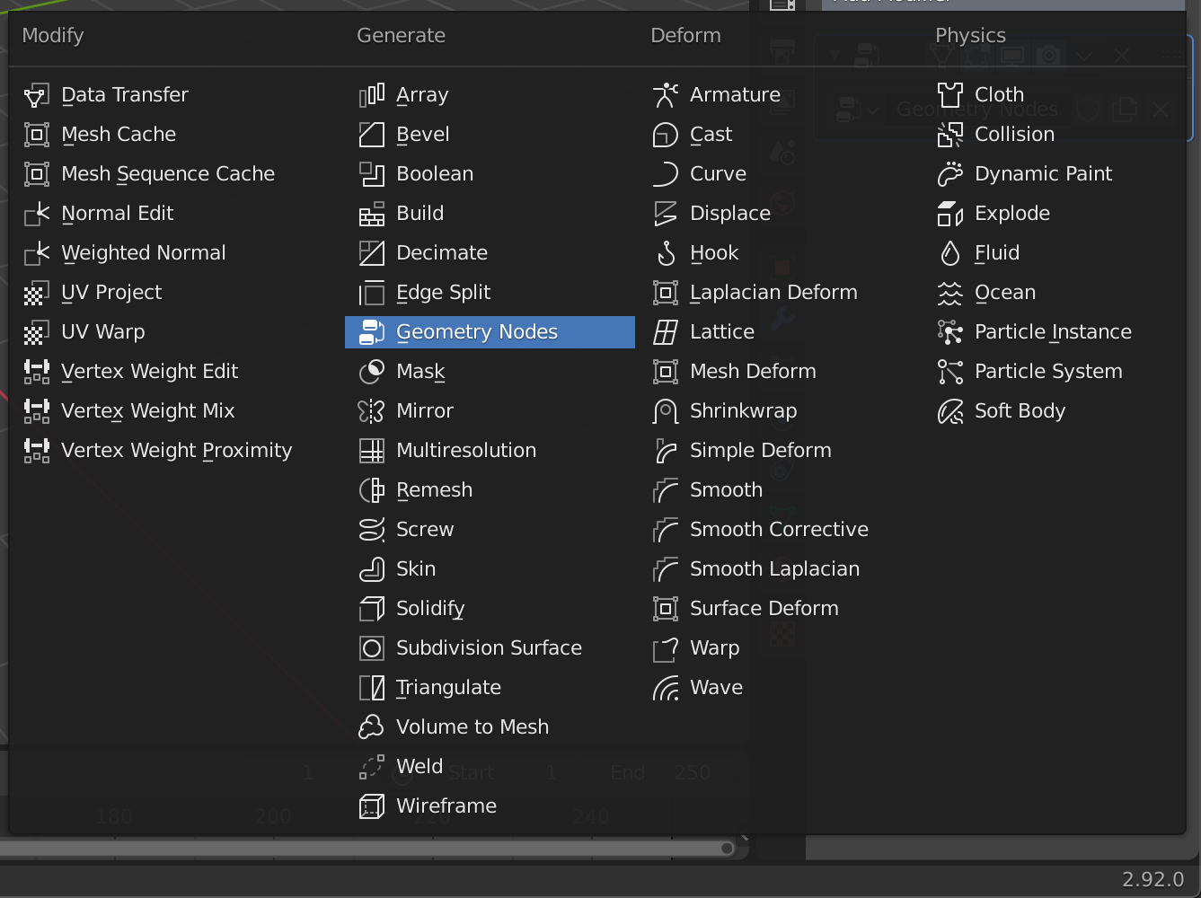
Geometry Nodes
To edit a geometry node, let’s switch the screen to the upper left icon.
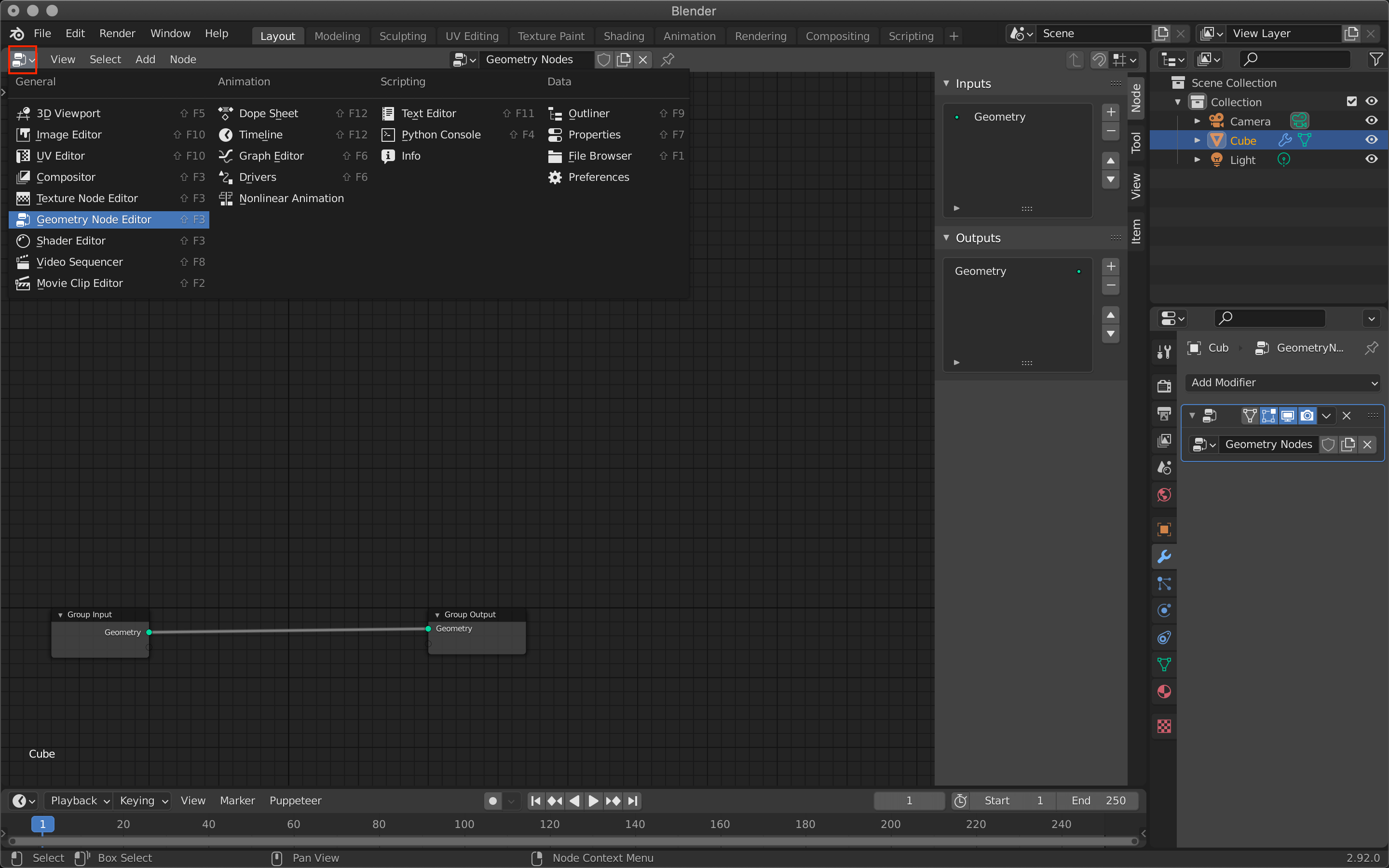
Switch to Node Geometry Node Editor with the upper left icon.
Add more screens for preview.

You can increase the screen from the upper right corner of the screen (click to confirm)
Create a motion graphic
Let’s create a motion graphic using the vertex data of the plane.
We will follow the steps below.
- Create a plane as a base.
- Assign a set of Spheres to the plane
- Set up the motion
- Set the object that moves the Sphere
Completed image (click to confirm)
Adding a Plane
First, select the default cube -> [X] to delete it, and [Shift+A] to add a plane.
![At the top of the screen, [Shift+A] -> Add Plane](https://styly.cc/wp-content/uploads/2021/06/Screenshot-161.png)
At the top of the screen, [Shift+A] -> Add Plane
[Tab] to switch to edit mode and subdivide the plane.
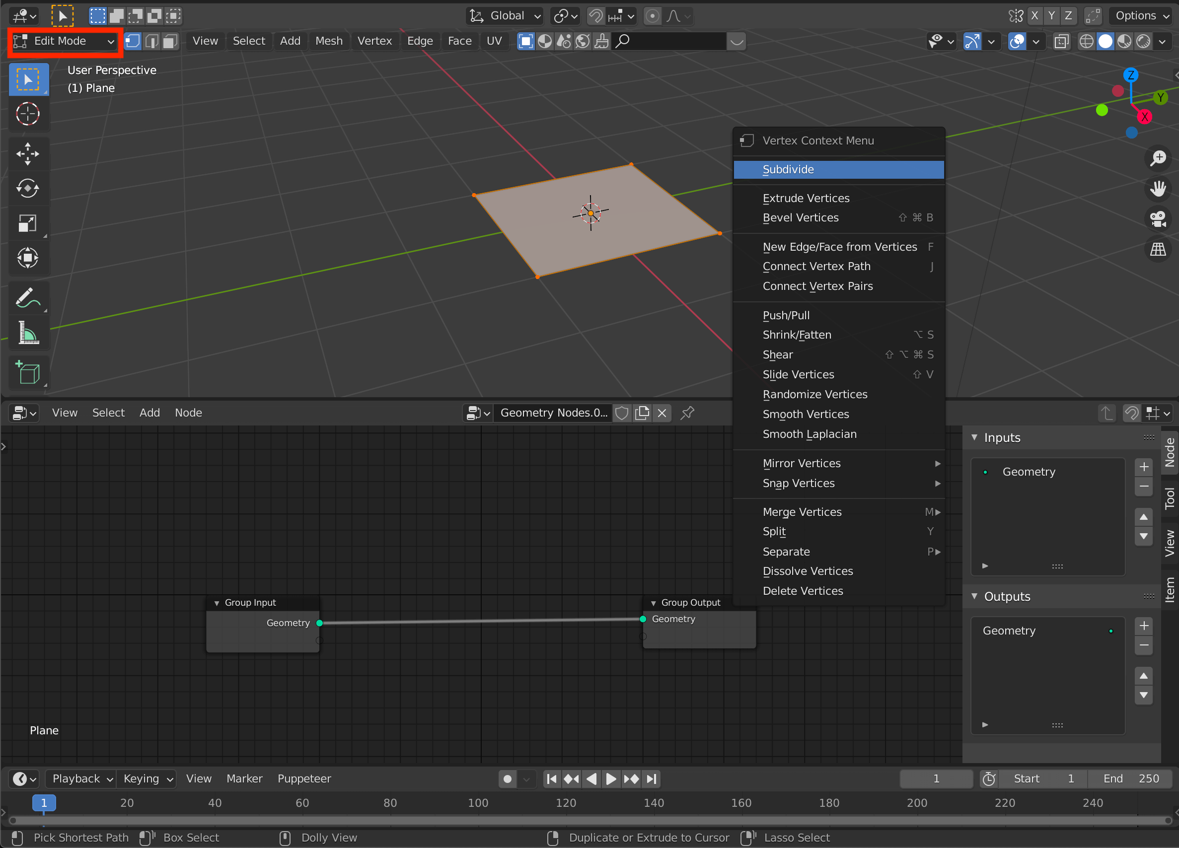
Right-click -> Subdivide
Change the “Number of Cuts” value to 10 in the menu at the bottom left to make it even finer.
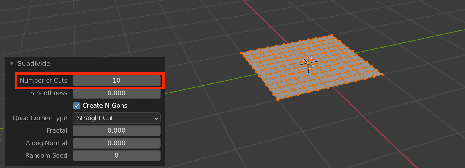
Number of Cuts
After deselecting the plane, add a Sphere.
![Switch to object mode by pressing [Tab], then [Shift+A]→Sphere.](https://styly.cc/wp-content/uploads/2021/06/Screenshot-162.png)
Switch to object mode by pressing [Tab], then [Shift+A]→Sphere.
Adding and Removing Nodes
Select the plane again and add geometry nodes from the modifier tool.
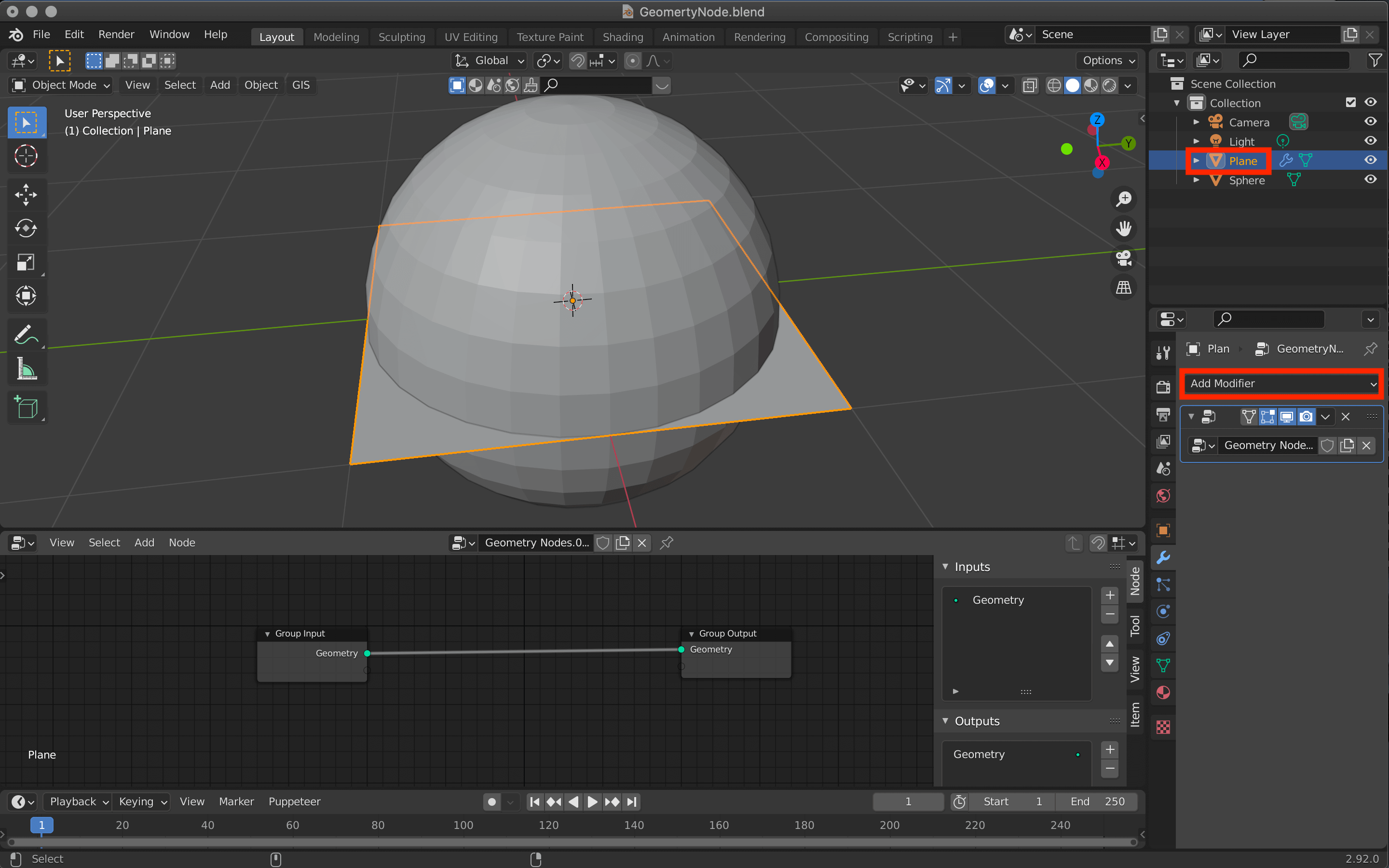
Geometry Nodes
Then press [Shift+A] on the Geometry Node Editor to add a node called Point Instance.
Move the cursor to the location where you want to add the node (in the case of Point Instance, between Group Input and Group Output), and click to connect it automatically.
Point Instance (click to confirm)
I added it from the Point menu, but it is convenient to search for it by typing its name in the Search section.
When you want to delete a node, click it and press [X].
Select a node and press X to delete it.
Assigning a Sphere
Click on the ■ of the Object in the Point Instance node and select the Sphere.
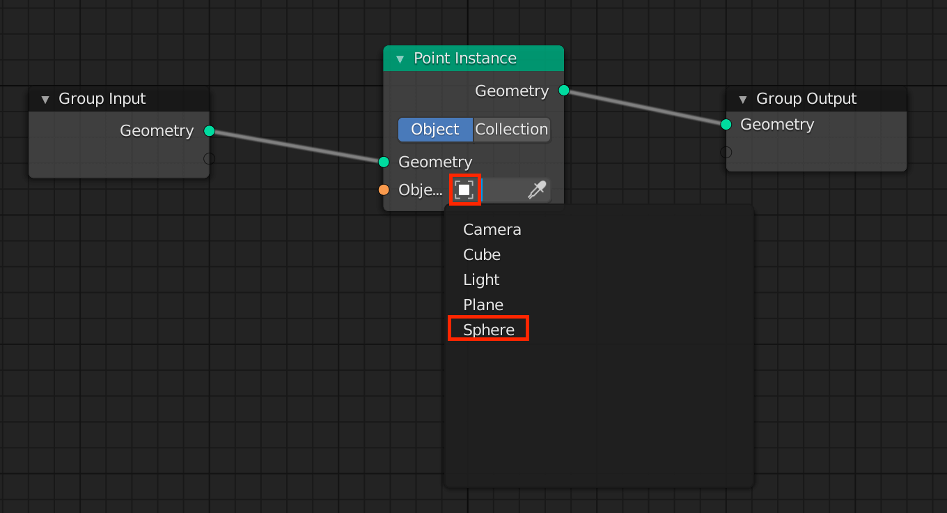
You can also use the eyedropper mark and click on the object directly.
The plane will change with the assigned Sphere and look like this.
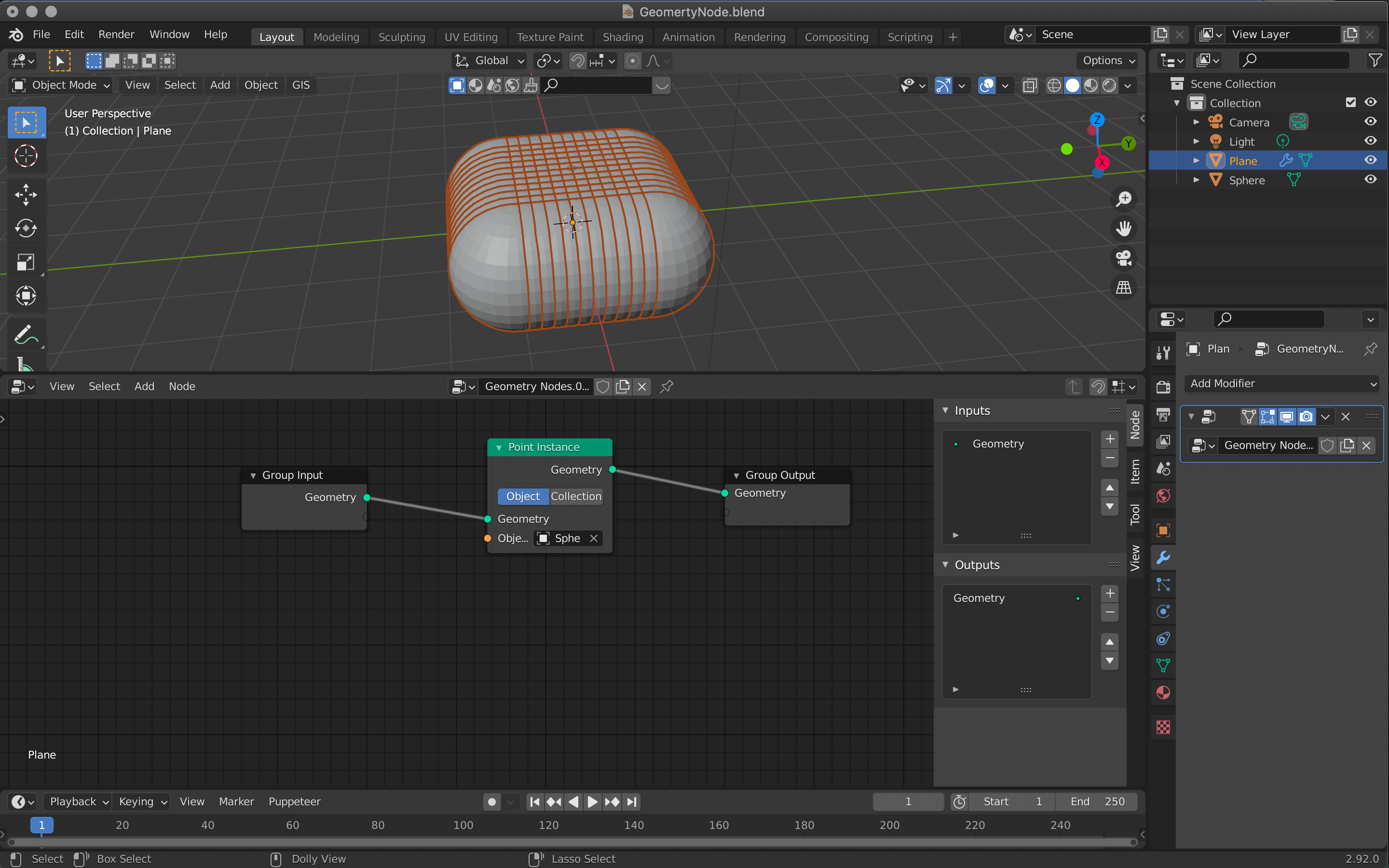
Each vertex of the plane has a Sphere assigned to it.
Adjust the size of the Sphere because it is too large for the plane.
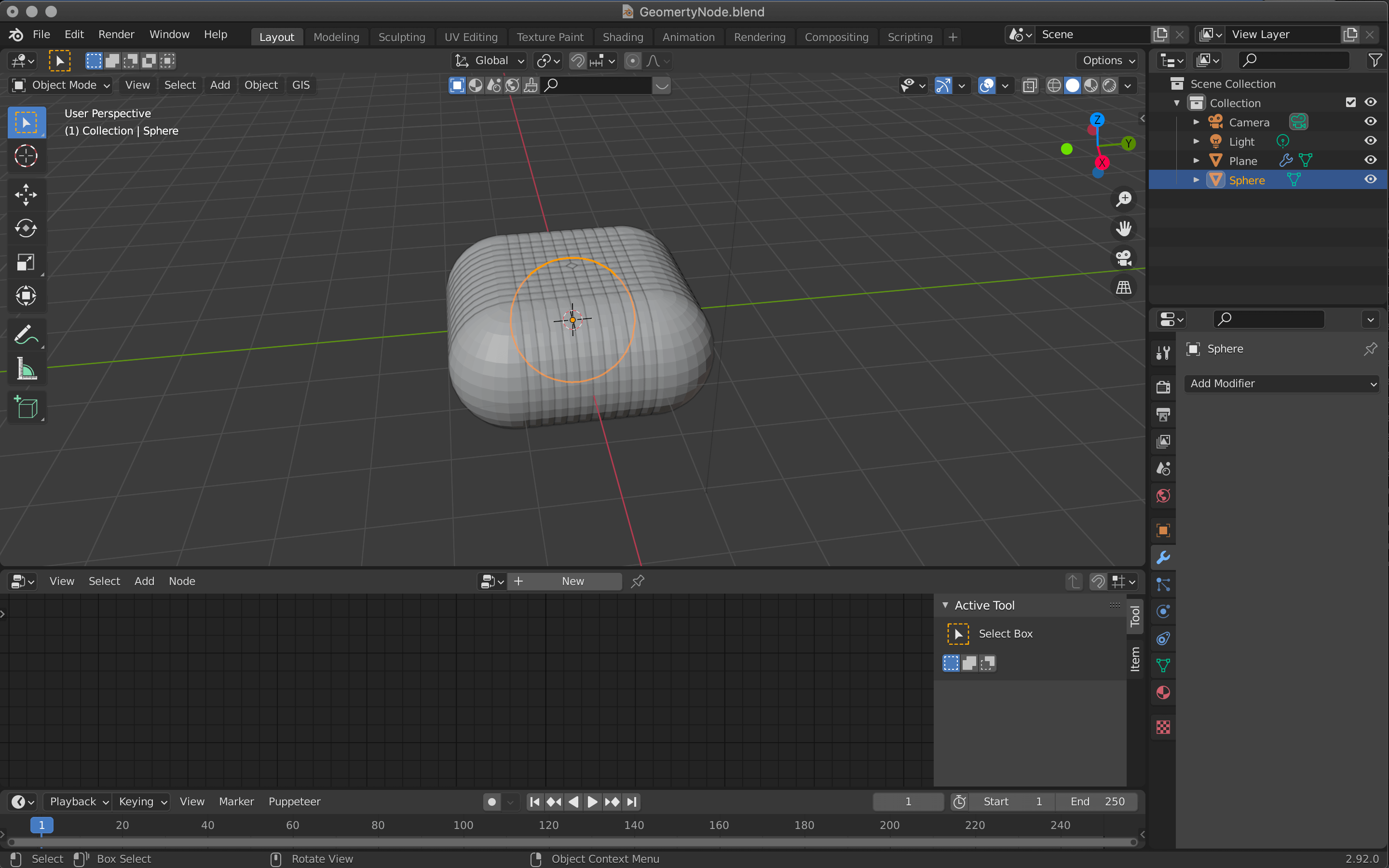
Select the Sphere
Use [Tab] to switch to edit mode, and then [S] → move the cursor to shrink the Sphere.
The size should be small enough that all the spheres do not overlap each other.

Click to confirm
Change the size of the Sphere with Attribute Fill
Use [Tab] to switch to object mode, select a plane, and switch to geometry node editing.
Use [Shift+A] to add a node called Attribute Fill between Group Input and Point Instance.
In this node, you can enter an attribute in the Attribute field and change the attribute by adjusting the value below it.
In this case, we will enter “scale” here, but other default attributes such as “position” and “rotate” are also available.
You can also enter other attributes and they will be created.
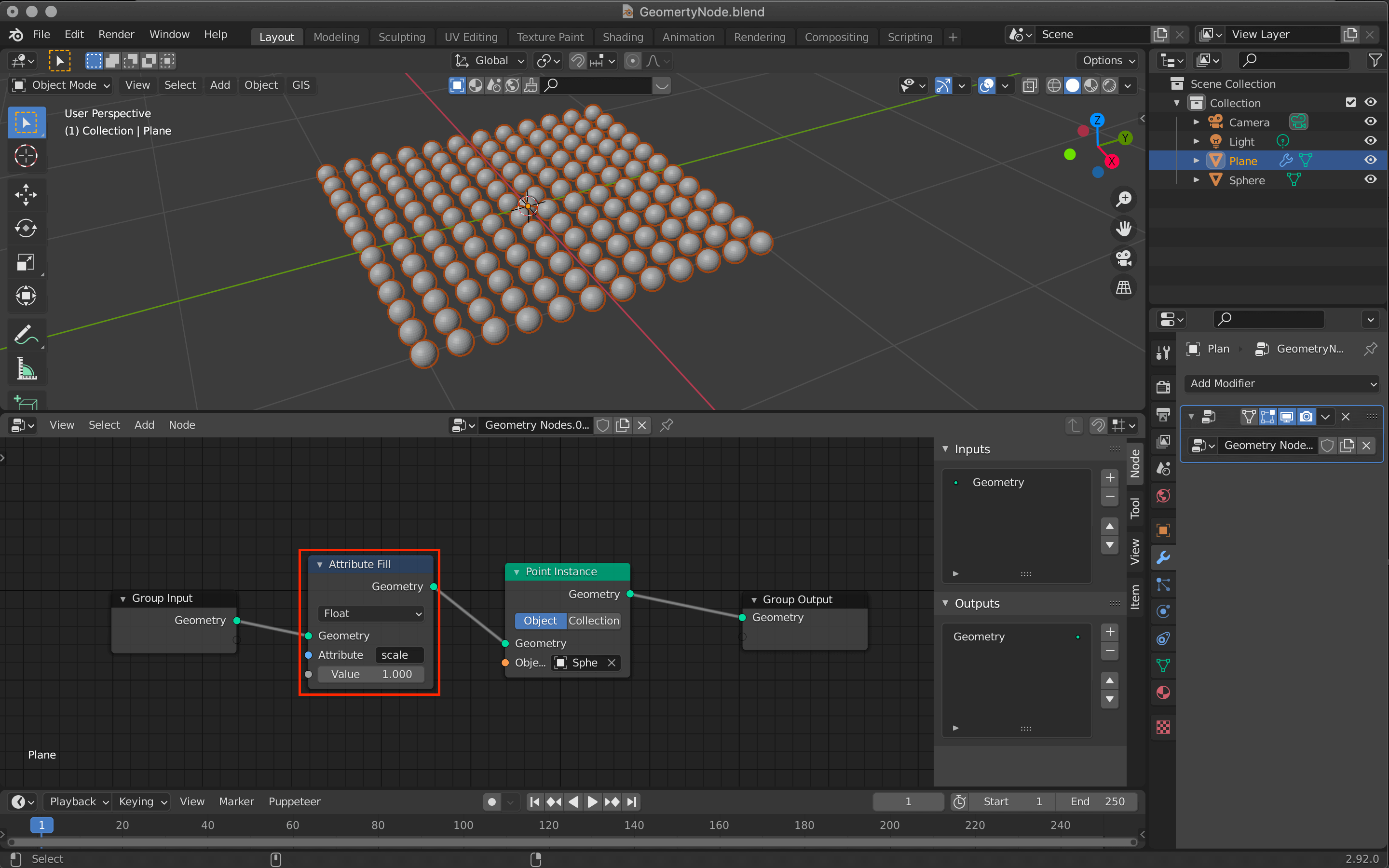
Attribute Fill
Now we can easily change the size of the sphere.
The value of the Attribute Fill is linked to the change in the size of the sphere (click to confirm).
Mixing Attribute Nodes with Attribute Mix
The next step is to add an Attribute Mix between the Attribute Fill and the Point Instance.
This node mixes the two Attribute nodes and creates a new Attribute node.
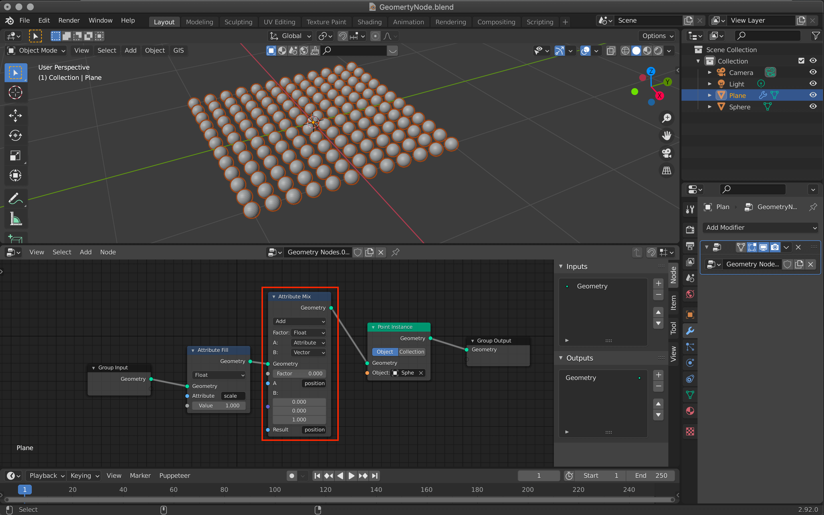
Attribute Mix
The changes are as follows
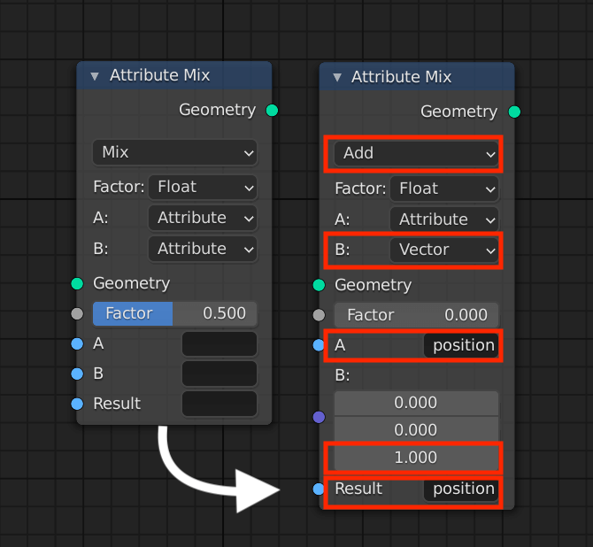
Attribute Mix
- Changed from Mix to Add
- Changed from B:Attribute to Vector
- Change the value of the third row of B: to 1.0
- Enter “position” in the “A” field
- Enter “position” in the “Result” field
You can see that the position of the sphere is also moved by changing the value of Factor.

Click to check
Moving Some Spheres with Vertex Group and Vertex Weight Proximity
Let’s add a Sphere to move some Spheres.
![In the window at the top of the screen, press [Shift+A]→Empty→Sphere](https://styly.cc/wp-content/uploads/2021/07/Screenshot-176-1.png)
In the window at the top of the screen, press [Shift+A]→Empty→Sphere
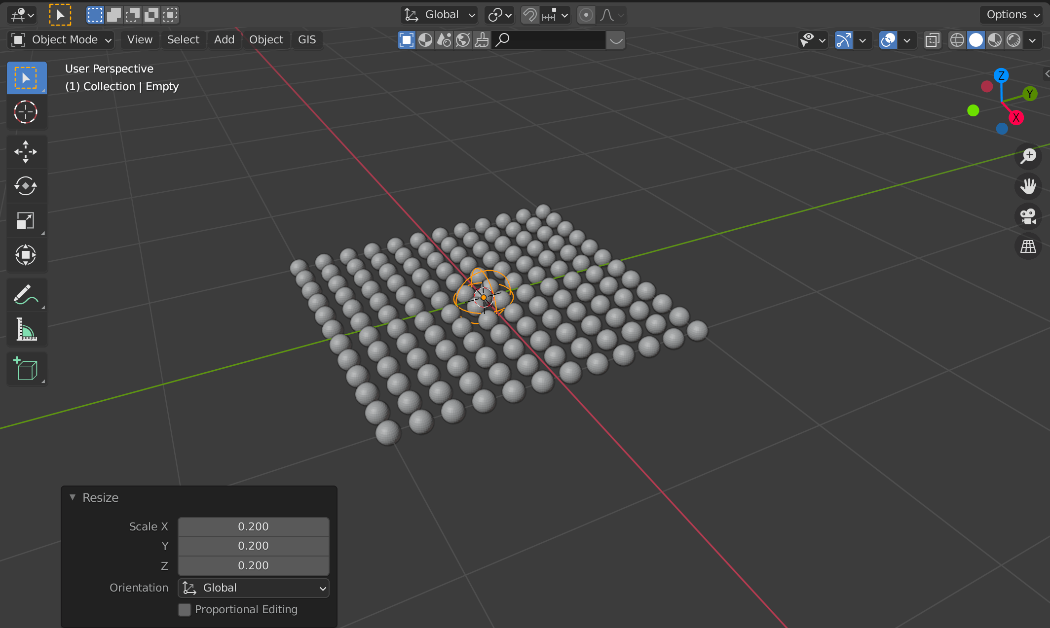
S key -> move the cursor to adjust the size
Select the Plane again and select the Object Data Properties icon.
Then click on the + button in Vertex Groups to register the plane.
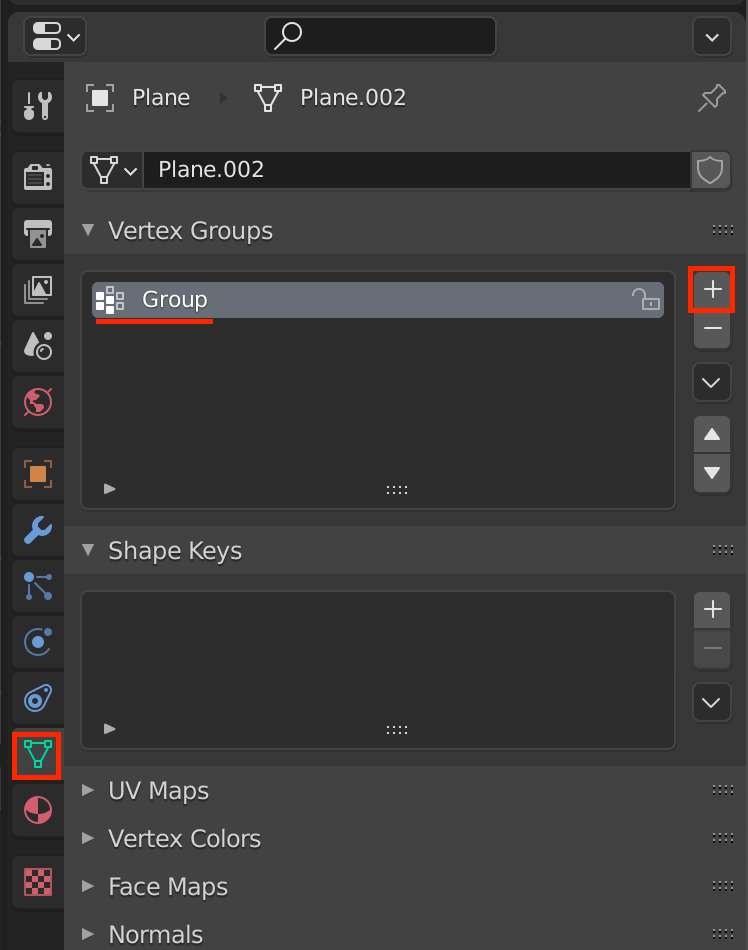
Vertex Groups
Click [Tab] to switch to edit mode, then click Assign to assign the selected plane.
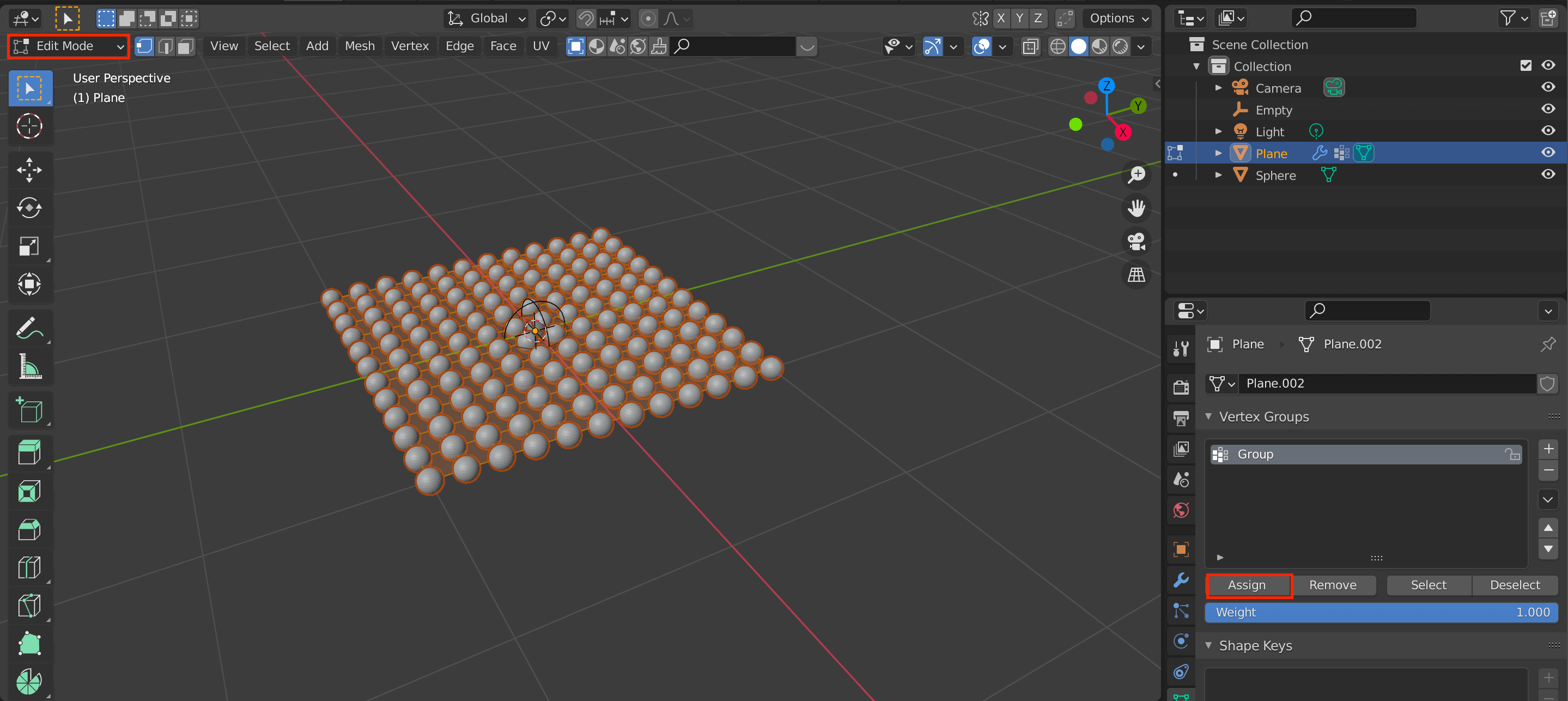
Assign
Go back to Modifier Properties and add Vertex Weight Proximity.
I’ll introduce this tool in detail in another article.
Modifier Properties
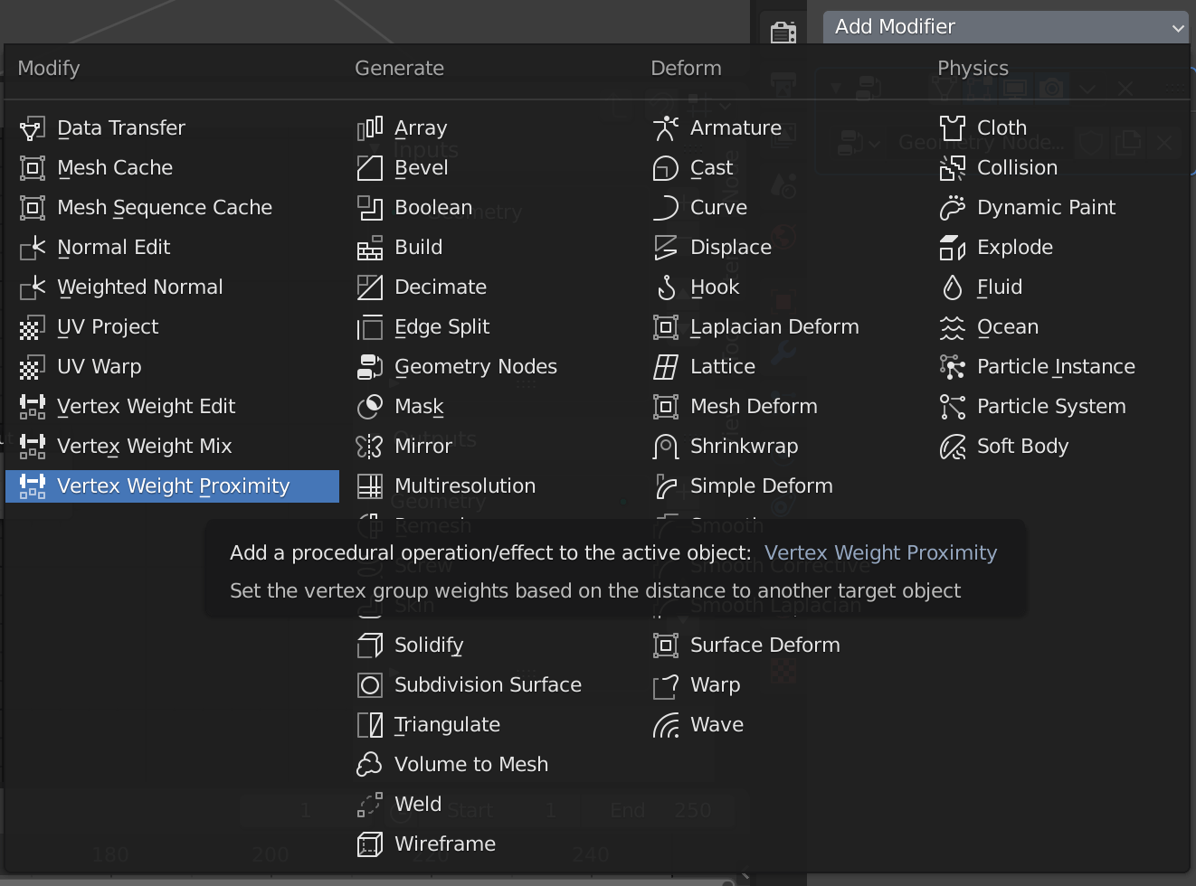
Vertex Weight Proximity
Assign the “Group” that you just registered to the Vertex Group item and Empty to the Target Object.
Set the Proximity Mode to Geometry.
Assign each object in a different order (click to confirm).
Edit the Weight Paint
Once the Geometry Nodes are hidden, switch to Weight Paint mode from the icon in the upper left corner.
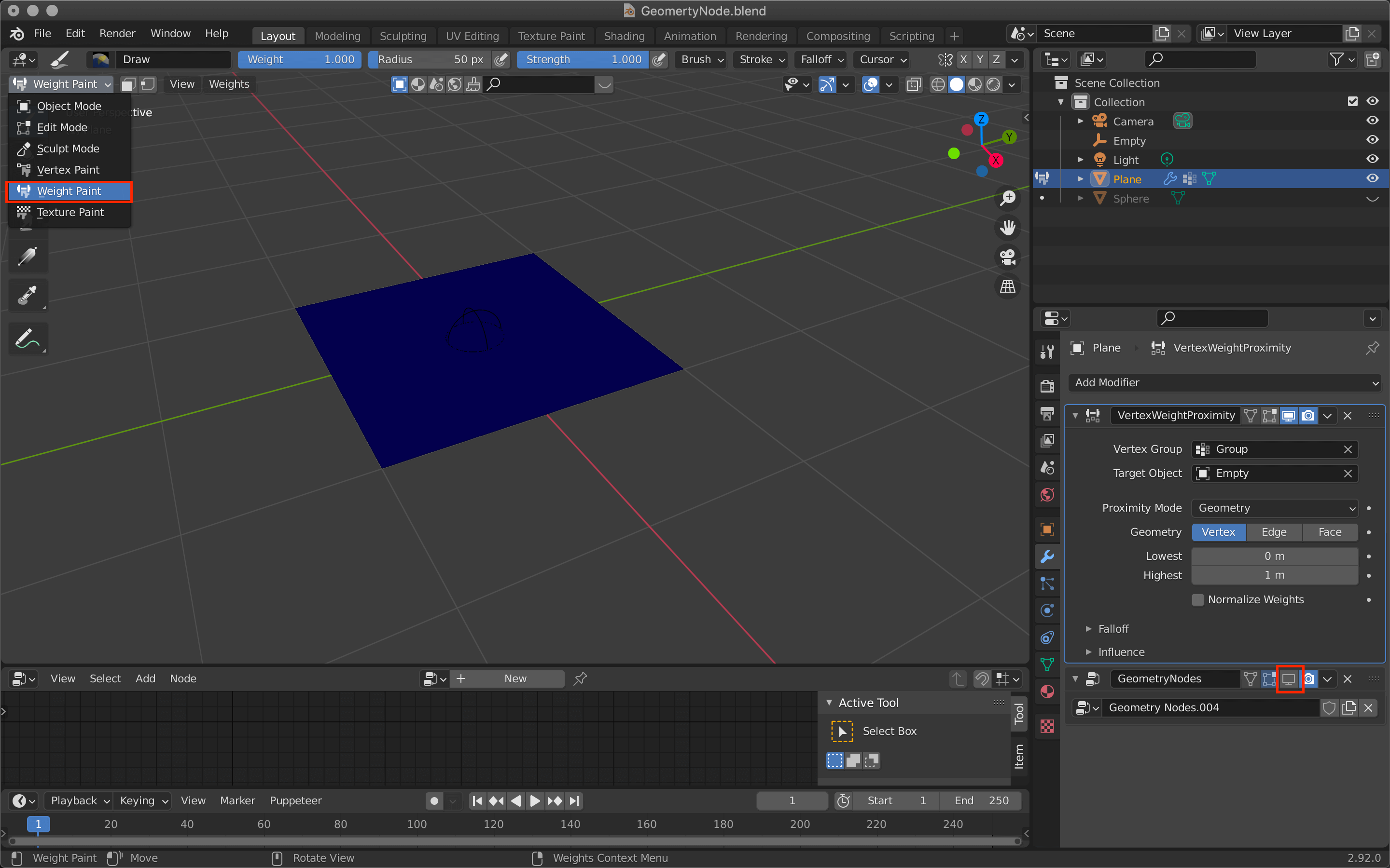
Weight Paint
Adjust the Lowest value to create a gradient circle in the center, as shown in the screenshot.
The size of this circle will be the range of influence when moving the Sphere assigned to the plane later on.
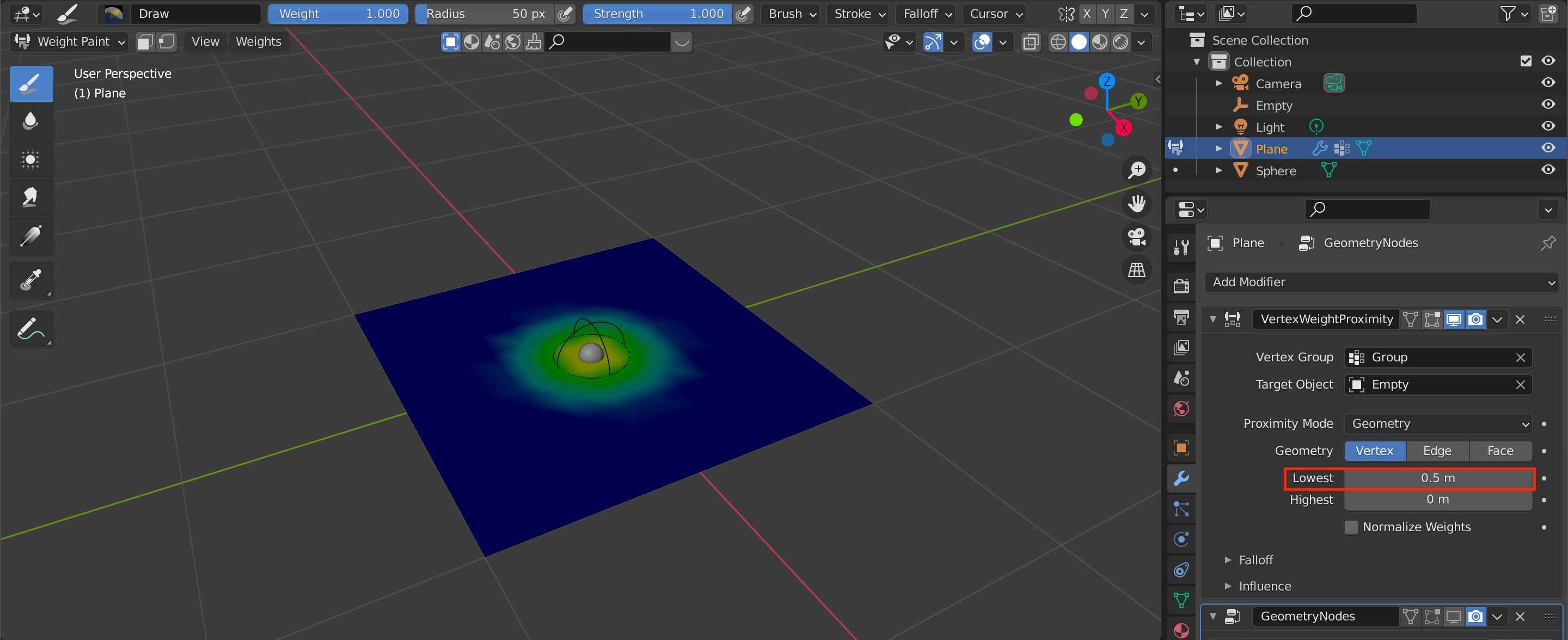
Since the plane is small, I set Lowest to 0.5.
Adding and editing the Attribute Mix
Click on the icon in the upper left corner to return to object mode.
- Select the Plane
- Click on the display icon of the geometry node in Modifier Properties to display the assigned sphere again
- Click on the node icon to return to node editing
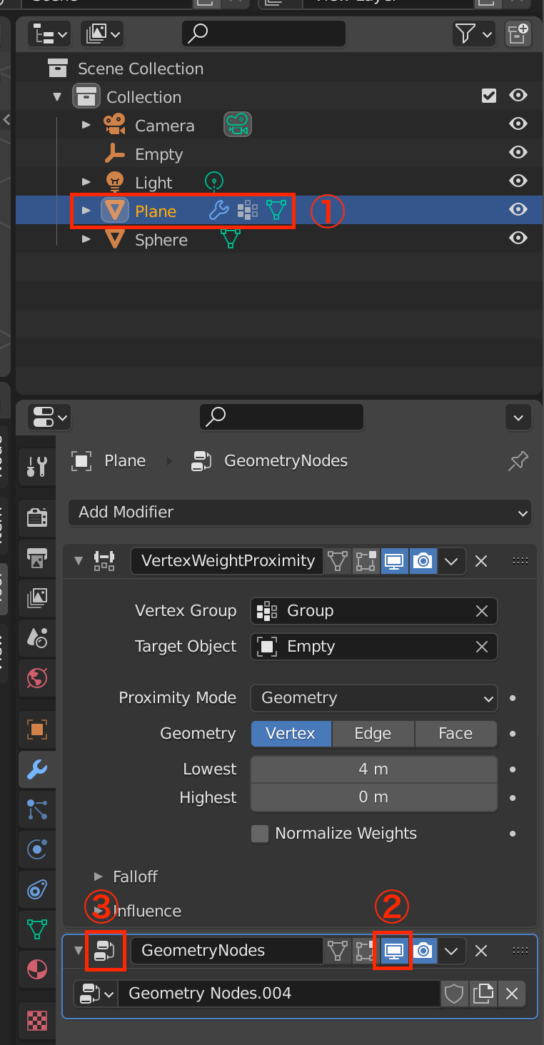
Select Plane -> Redisplay Sphere -> Redisplay Node and Edit
Once you have selected the Attribute Mix node, copy and paste it into the new node between the original Attribute Mix and the Point Instance.
Adding an Attribute Mix
Then edit the node you added.
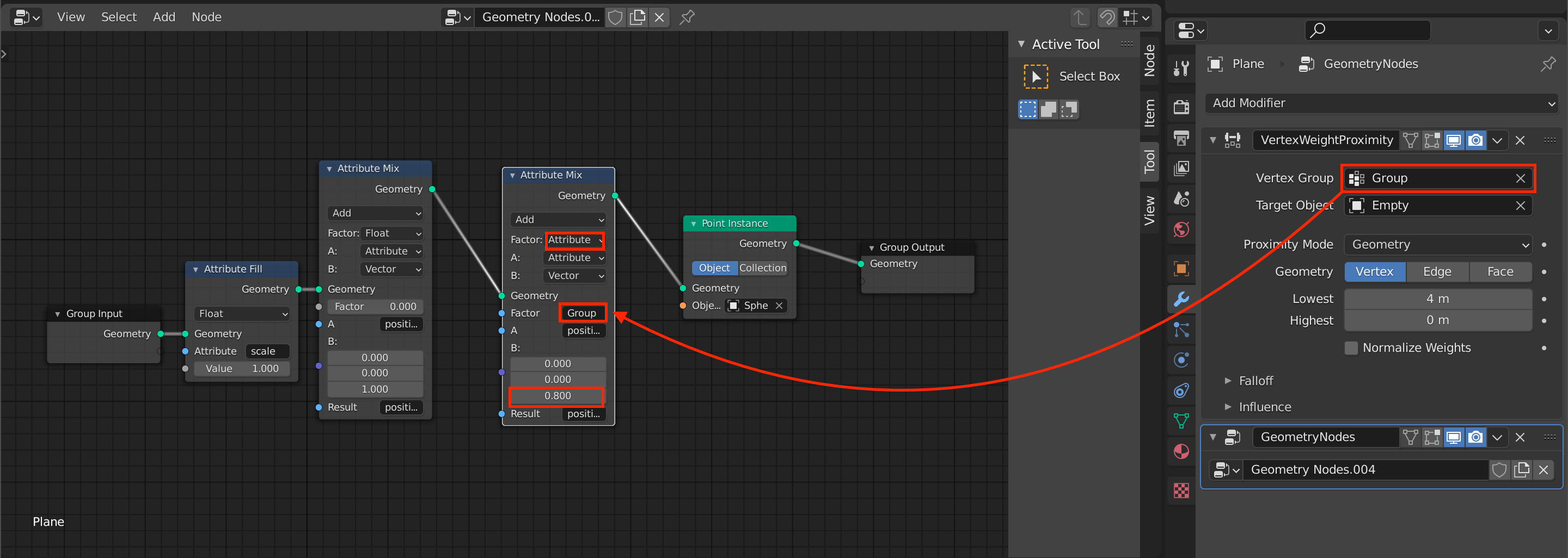
Change the node values, etc.
- Change the Factor from Float to Attribute
- Enter the Group (the name of the Vertex Group you just registered) in the second Factor field.
- Adjust the value at the bottom of B:.
Now all the settings are complete!
Select Plenty, click [G], and move the cursor to see the Sphere moving with it.
There are many more functions in Geometry Nodes alone, so please try them out.
The assigned Spheres are moving together (click to confirm).