Hello everyone, this is noria901.
In the last article, I showed you how to create a textured mesh from 8 photogrammetric photos.
You can use them in STYLY by exporting them as described in this article and uploading them from Unity!
By the way, is there any dust, holes, or unevenness in your photogrammetric model? If you feel that way, it means that the current model cannot be used in STYLY. In such a case, it’s time to process the model! When we talk about model processing, modeling software such as Blender comes into play, but actually, photogrammetric tools themselves have processing functions.
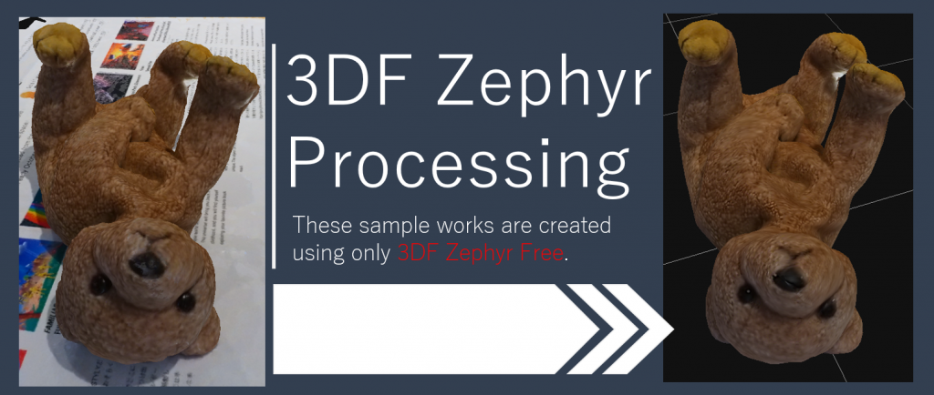
The free version of 3DF Zephy also offers advanced features.
Getting Started
3DF Zephyr is a photogrammetric tool available for Windows. Since some of you may not be familiar with it, let’s review the basic workflow of 3DF Zephyr.
Reviewing the 3DF Zephyr workflow
The workflow of 3DF Zephyr is simply to generate and output a model according to the workflow. In particular, the workflow up to model creation is organized in the Workflow menu. If you just want to create a model, you can do so in three steps:
- create a new project
- create a 3D model
- create a textured mesh.
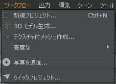
Just press them in order from the top.
| Workflow | Description |
| New Project |
|
| 3D Model Generation |
|
| Creating a textured mesh |
|
| Advanced |
|
| Add photo |
|
| Quick Project |
|
There are three ways of exporting the completed model in the Output menu.
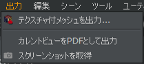
There are three ways to export
| Output | Description |
| Output a textured mesh |
|
| Output the current view as a PDF |
|
| Get a screenshot |
|
Now you can get Obj models from photos. But did you know that when you generate a textured mesh, the mesh may be thinned out and the model may be degraded? In order to get a clean model, you need to know about “thinning” when creating a textured mesh.
“Thinning” when creating a textured mesh
What is a clean model? One way to think of it is that the more vertices and polygons in the final model, the higher the definition (i.e., the cleaner the model). However, the more vertices and polygons, the more computations are required and the heavier the PC becomes. As a result, the overall experience of the scene created using the model may be degraded. Therefore, it is necessary to consider “thinning out” vertices and polygons to the extent that the appearance is not affected.
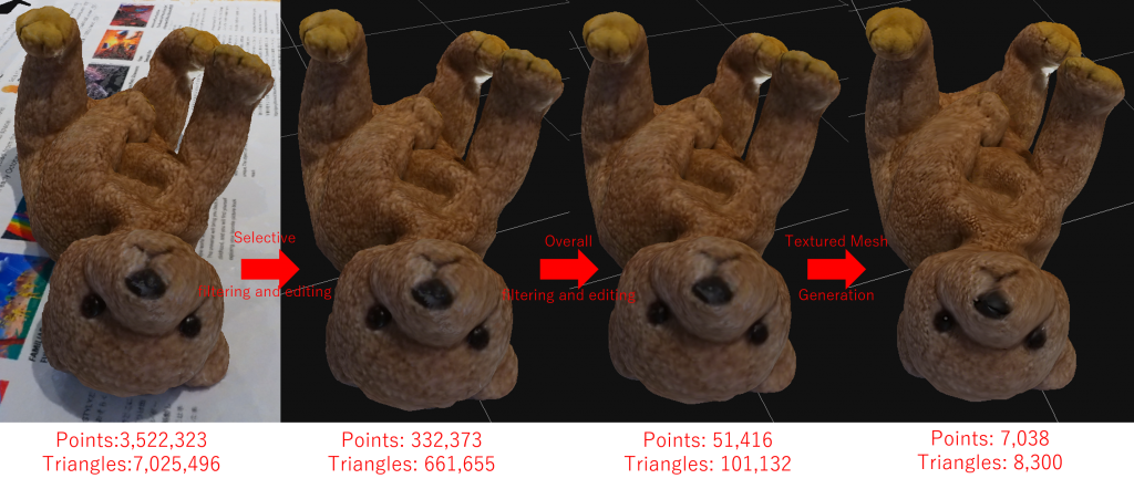
The current vertex count of a mesh can be checked by viewing the properties of the mesh. Where it says “points” is the number of vertices. For example, in this example, the number of vertices is 3,522,323.
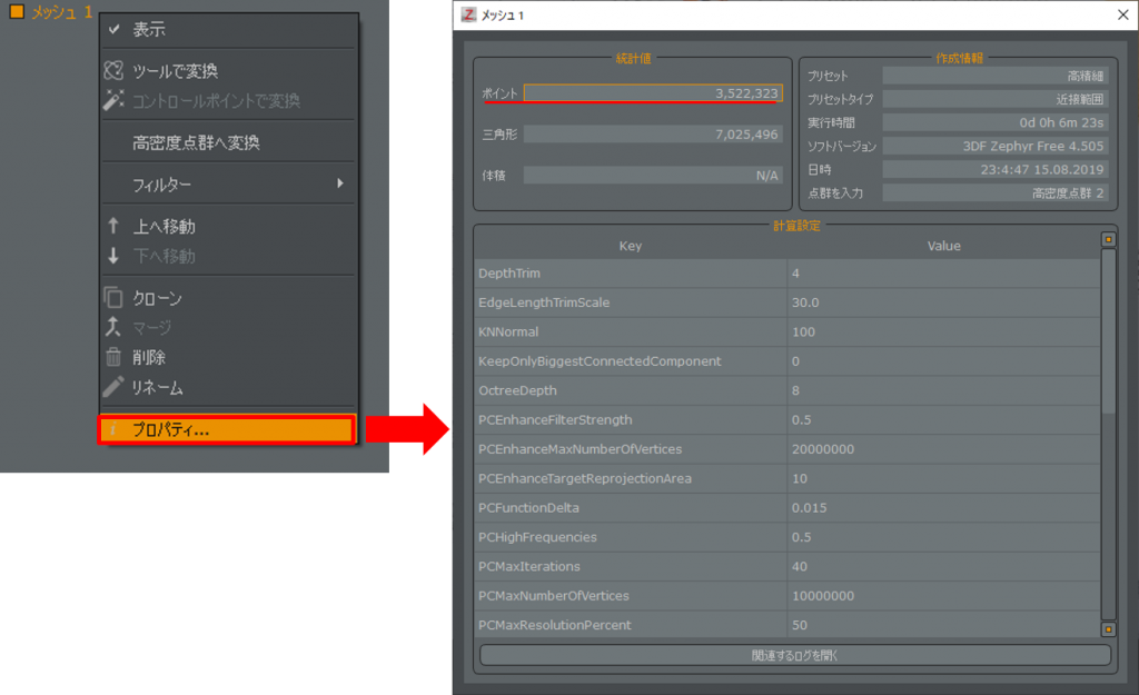
If you look at the points section, there are 3,522,323 vertices. That’s a lot.
So let’s thin it out quickly. If you change to Advanced in the Textured Mesh Wizard, you will see that there is a setting for Maximum Vertices. The maximum vertex is set by default to the same value as the number of vertices in the mesh. This means that it is in high definition. If this setting is not changed, the process may become heavy when multiple models are placed on STYLY. So in order to thin out the number of vertices, let’s create a model with the maximum vertex setting of the Textured Mesh Wizard set to 5000.
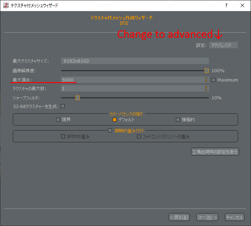
Change it to Advanced to see the maximum vertex count setting.
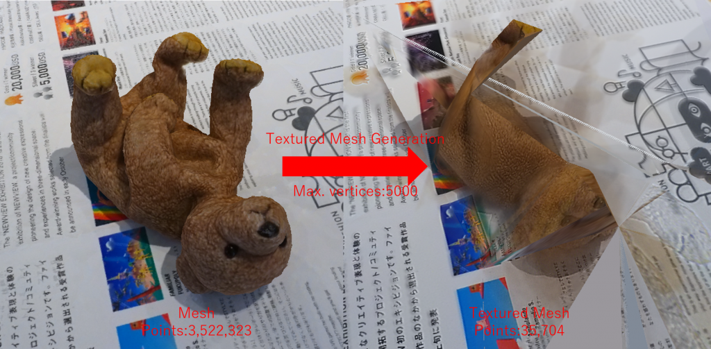
After thinning out the model, it broke.
The mesh broke because it was suddenly thinned from a high number of vertices to a low number of vertices, making the model unusable as is. As you can see, there is a tradeoff between thinning and high definition. To avoid this, the number of vertices in the mesh must be reduced sufficiently before performing thinning when creating a textured mesh. 3DF Zephyr provides a processing capability for this purpose.
3DF Zephyr has a processing capability for dense point clouds and meshes. As of version 4.5 of 3DF Zephyr, dense point cloud creation and mesh creation have been combined into a workflow called “3D model creation”. Therefore, it is common to process the meshes that are obtained when the “3D model creation” is completed. Therefore, in the following explanations, we will focus on mesh processing.
Whole and partial processing
There is a range of applications for the processing function. In other words, you can either process the whole mesh or just a part of it. In my opinion, it is better to process the part you are interested in first, and then process the whole mesh. Processing the area of concern means, as mentioned at the beginning of this article, deleting unnecessary meshes, filling holes in meshes, and cleaning up unevenness in meshes. After this process, the number of vertices is inevitably reduced to some extent. Then, the number of vertices is further reduced while preparing the entire image.
It is possible to undo this process, but it is better to clone the mesh and save the project as a precaution.
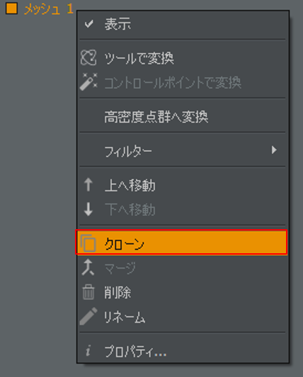
Clone and save before processing
We are now ready to go. Let’s try to delete the extra meshes.
Deleting extra meshes
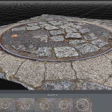
If you have created a 3D model with a bounding box set up, you have probably removed some of the excess. However, there are still some superfluous parts left in the target object. Let’s select and delete these superfluous meshes. The means of selection are gathered in the Selection palette.
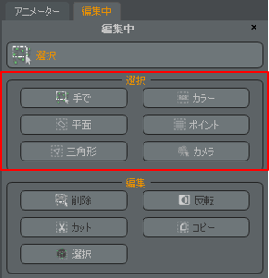
Selection functions are grouped in the Selection palette.
|
Selection |
Description |
| By hand | A method of selection that is similar to that of common painting tools, where you select by delimiting areas. |
| Color | Select based on the color of the texture. |
| Plane | Selects a mesh on one side of a plane. |
| Point | Selection method for high-density point clouds only. It is not used for meshes. |
| Triangle | Selects polygons with edges longer than a certain threshold. |
| Camera | Selects an aligned camera. Not used for meshes. |
Let’s try to use polylines to select from “by hand”. For example, if you don’t need the floor mesh, you can select it by wrapping it around the floor mesh. The area where the mesh turns red will be the selected area.
Draw a polyline and select the area
Now let’s delete the selected extra mesh. The editing options for the selected meshes are listed in the Editing palette.
| Edit method |
Description |
| Delete | Delete the mesh in the selected area; you can also delete it by pressing the Del key. |
| Invert | Invert the selected area. |
| Cut | Cut the selected area as a separate mesh. |
| Copy | Copy the selected area as a separate mesh. |
| Select | Apply a filter to the selected area. |
In this case, the area you want to keep is selected, so you can delete it after inverting.
You can also delete the selected area with the Delete key.
Selection “by hand” selects all meshes in the selection area. It is very easy to select only the side of the model and then select the other side. In such a case, you can deselect only a part of the mesh by selecting the “Delete” mode in the selection dialog and then selecting the unneeded area again. Conversely, you can add selections by using the “Add” mode.
Unnecessary selections can be deselected.
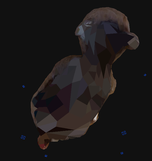
There are still some small meshes left, but after repeating the deletion process, the garbage is gone.
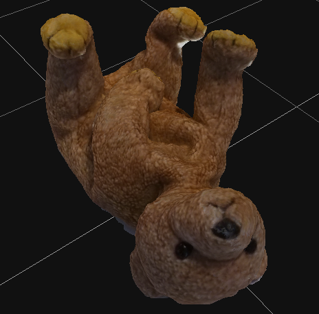
A bad bear with cleanly disappeared garbage
Filling holes in the mesh
Areas that have not been photographed enough or thin objects tend to have holes in the mesh. There are two functions in the Filtering palette to fill these holes.
| Hole filling function |
Description |
| Selective Hole Filling | A function that looks for holes where the mesh is not closed and selects holes to fill. |
| Watertight | Finds holes where the mesh is not closed and fills all the holes. |
Which one to use depends on the case, but for photogrammetry such as small objects, filling all the holes is fine. In the case of wide area photogrammetry, filling holes often results in unintentional shapes, so it is better to use selective hole filling to fill holes steadily.
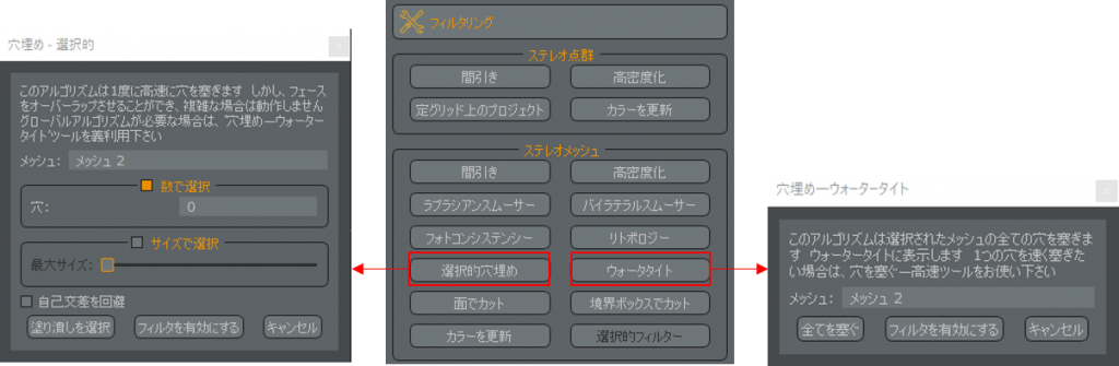
Selective filling or filling all at once?
In the case of selective hole filling, there are two options: “select by number” to plug specific holes, and “select by size” to plug specific holes. When you have successfully selected the holes you want to fill, select “Select Fill” or “Enable Filter.” If you select “Fill”, the mesh will be directly modified. If you want to keep the current mesh, choose “Enable Filter”.
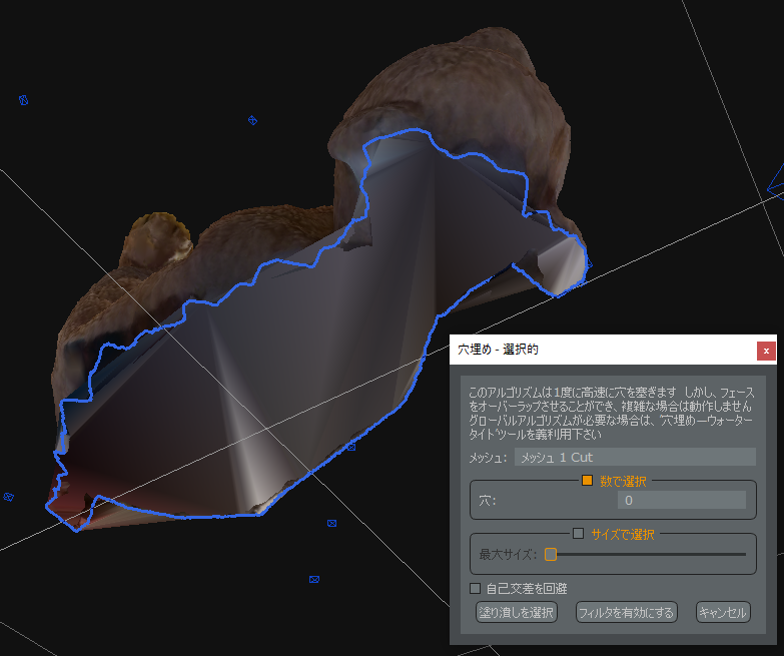
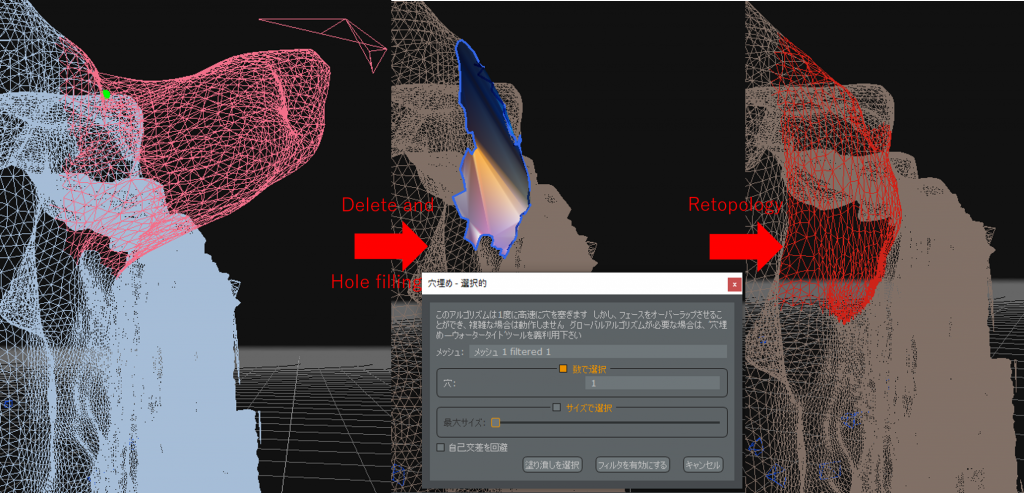
Try to fill the holes on the surface that touches the desk.
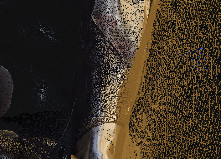
This may look like it is filled, but the mesh is actually very rough. Activate “Show Wireframe” to see the rough state of the mesh. If you create a textured mesh while the mesh is rough, it will break easily, so repair the rough mesh.
Displaying wire frames shows the state of the mesh.
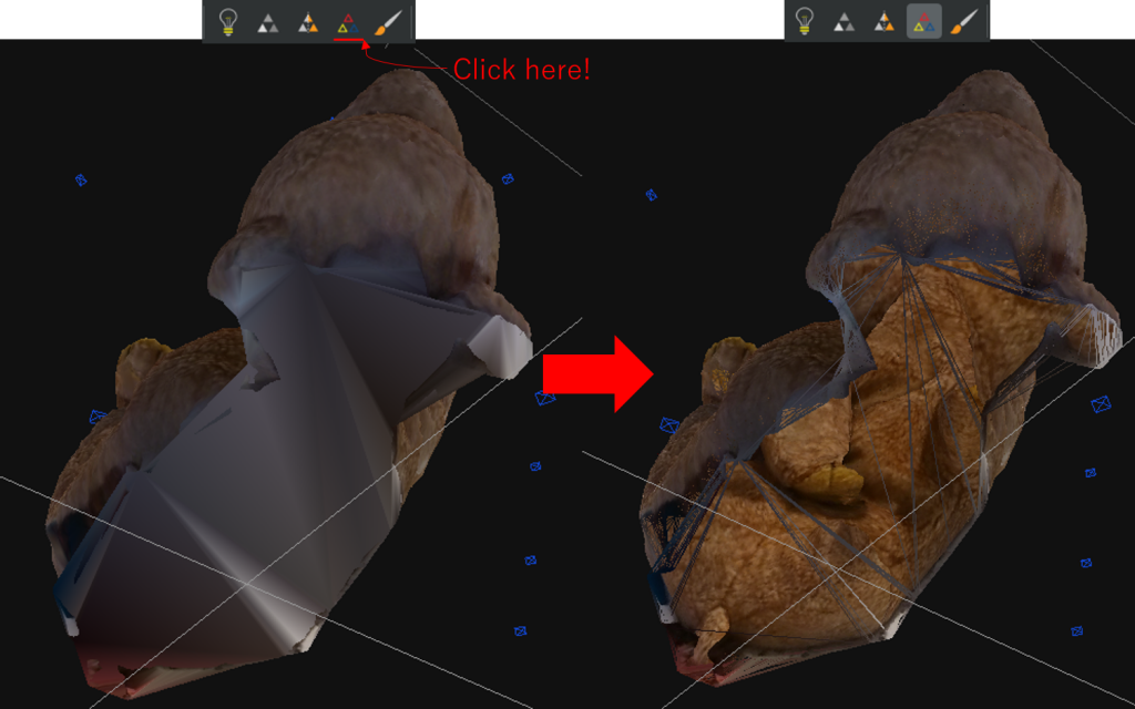
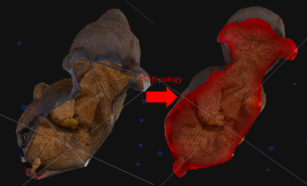
To repair the rough mesh, we will use a filter called Retopology. Select a larger area around the rough mesh and select “Select” in the Edit panel or “Selective Filter” in the Filtering panel to open the Selective Filter dialog. You can select a retopology from the list and run it to partially refine the mesh.
Selecting and then retopologizing will clean up the mesh in the selected area.
The number of iterations is the number of times you want to retopologize. Increasing the number of iterations will make the mesh cleaner, but it will take more time, so be sure to specify a moderate number of iterations.
The result of selecting and retopologizing. If it’s not enough, you can add more.
By the way, I filled in the hole in the back of the bear as an example, but you may not need to fill in the hole. For example, if you are going to place the bear in a lying position on a bed, the hole in the back will be buried in the bed and will not be visible. Also, since we don’t have a picture of the back, even if we create a textured mesh, it won’t generate a nice texture. In order to reduce the number of vertices, let’s consider the possibility of not filling the hole.
Do you really need to fill that hole?
When a hole is present but not recognized as a hole
There are times when you can’t fill a hole even if you do all the above. A common example is a battern that looks like it has a hole but the mesh is closed. This is especially likely to happen with thin objects.
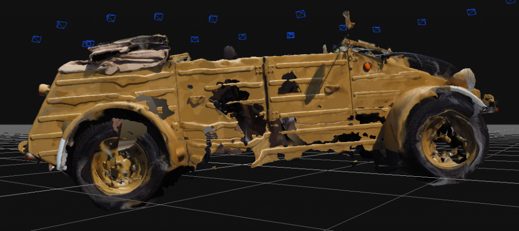
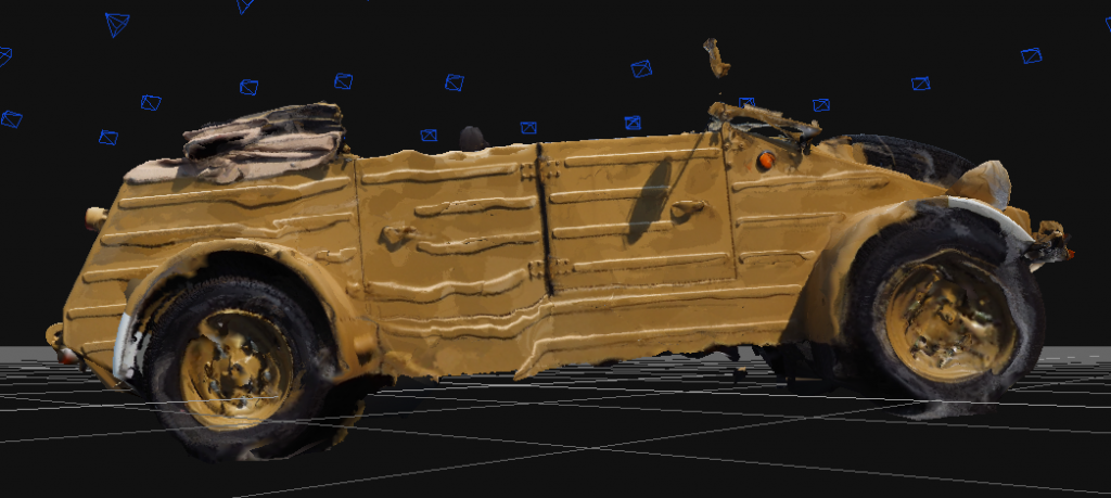
I had a car door that was so thin it was falling apart.
If you look at the hole from the side, you can see that it is connected to the mesh on the other side.
In this case, you can remove the closed mesh and make a hole in it.
Select the closed mesh and delete it, and you will find two holes.
The holes are now cleanly filled.
3DF Zephyr is all that is needed to plug the holes.
Cleaning up the unevenness of the mesh
The mesh may be uneven if the light source or the feature points of the object are difficult to capture. Let’s fix this.
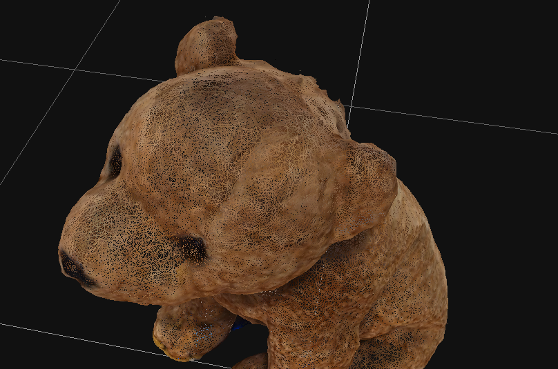
The back of the head is uneven. This is worrisome.
The basic operation is the same as before: select and apply a filter. These are the two filters we will use.
| Filter | Description |
| Laplacian Smoother | This filter flattens uneven surfaces. If you use it on a sphere, it will make it thin. It is recommended to use this filter when creating a flat surface. |
| Bilateral Smoother | This filter emphasizes edges and flattens fine bumps. It is good to use this filter when you want to emphasize angular areas. |
In this case, we want to flatten the image, so the Laplacian Smoother is appropriate. Let’s select the image and try applying the Laplacian Smoother. The more iterations, the flatter the image becomes. As it gets flatter, there are more planes, so there may be more unwanted meshes. This is what it looks like when you retopologize it in the selected state.
Laplacian Smoother smoothes out the bumps.
As a result of the previous processing, there are times when the edges are squashed. In such a case, select it and apply a bilateral smoother.
It’s hard to tell, but the edges stand out without destroying the overall roundness.
Now the unevenness is cleaned up.
Application: Smoothing out a protruding mesh
Depending on how the light hits the mesh, it may pop out extremely. It is very difficult to flatten this out using the Laplacian Smoother. In this case, it is possible to create a flat surface by selecting only the protruding area, deleting it, creating a hole, and plugging the hole. Since the hole is affected by the surrounding mesh, it is best to delete the mesh so that only the flat mesh around the extremely protruding mesh remains.
It is faster to delete the protruding unevenness and fill in the holes.
If the area of the plane is large, perhaps it is not necessary to fill the holes. Even a plane will have a reasonable number of vertices. If this is the case, remember that you may want to leave the plane with a hole in it, and later combine it with a texture that matches the plane on the poly. For more examples of this, please refer to [Photogrammetry] Architectural Digital Archive #3: Post-processing.
This completes the processing of all the areas of concern. You can see that the model is still beautiful enough to look good, but if you add one more step, you will be able to express it with fewer vertices. That’s right, we need to adjust the whole model.
Adjusting the whole model
Now let’s see how much the number of vertices has been reduced from the beginning. If we look at the mesh properties, we can see that we now have 332,373 vertices, or 3,189,950 fewer than before. The number of vertices has been reduced enough even with the partial modification, but we can optimize the number of vertices further by applying filters such as retopology to the entire mesh.
The number of vertices can be greatly reduced just by retopologizing the entire image, but before doing so, we should think about how to handle minor irregularities. We just cleaned up some of the unevenness, but it would be difficult to select and then smoother all of the unevenness. If the entire image is uneven, now is the time to apply a Laplacian smoother to the entire image. Then retopology can be done. On the other hand, if the model has important borders, you should apply a bilateral smoother to emphasize the borders, and then apply the retopology.
Since the model has a lot of roundness, I applied a Laplacian smoother.
Now the number of vertices has been optimized and we are done with the overall alignment. The current number of vertices is 51,416, and by adjusting the entire model we were able to reduce it by 280,957 vertices. In this state, I can create a clean model without breaking the textured mesh even if I thin it out with the maximum number of vertices set to 5000. I have created a textured mesh with 7,038 vertices, which should not be too heavy for my PC. Let’s upload the model to STYLY. For more information on how to upload your model, see Introduction to Photogrammetry: How to Shoot – Creating 3D Models.
The number of vertices may decrease, but the cuteness does not.
Application: Combining with STYLY
In the previous section, we talked about deliberately creating holes in a flat surface. In addition to simple textures, you can combine them with video to create more dynamic works. All of these operations can be done in STYLY. There are also various ways to express models created with photogrammetry, such as using a hole as an expression of brokenness.
You can check out a sample scene from STYLY GALLARY that uses the model that appeared in this example.
10
Due to the use of unprocessed models, some PCs and other devices may not finish loading or may run slowly. In that case, please click here.
Conclusion
In the end, it’s best to use a tool that you are comfortable with, such as Metashape, or you can use a modeling tool like Blender to create a textured mesh without thinning. Metashape has a similar function, and you can also use modeling tools such as Blender without thinning when creating textured meshes in the first place. However, in such a situation, knowing that photogrammetric tools can do some light processing will make your work more efficient. There are other features in 3DF Zephyr that I could not explain in this article. If you are interested in learning more about 3DF Zephyr, please check out the 3DF Zephyr tutorials available in English.