This article shows how to use Blender’s standard Geometry Nodes feature to create objects with unique organic shapes.
This article is a continuation of the following article:
What are Geometry Nodes?
Geometry Nodes is a Blender feature that modifies the geometry of an object on the basis of nodes.
It is used by adding a Geometry Nodes Modifier to an object.
By connecting elements called nodes to create a node tree, animation and modeling can be performed.
In this case, Blender 3.1 is used since Dual Mesh Node does not exist in Blender 3.0 or earlier.
Usage Examples
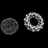
In this article, we will create a node-based Voronoi structure similar to the object created with the Dual Mesh feature described in the Tissue Tools article above.
The advantages of using Geometry Nodes include the ability to create more unique shapes and easily transfer them to another object of a different shape.
Let’s create one together.
The first step is to place a mesh in the 3D view.
The mesh can be any shape, but for this example, we will use the Cube that is placed by default.
Click on the Geometry Nodes Workspace at the top of the screen.
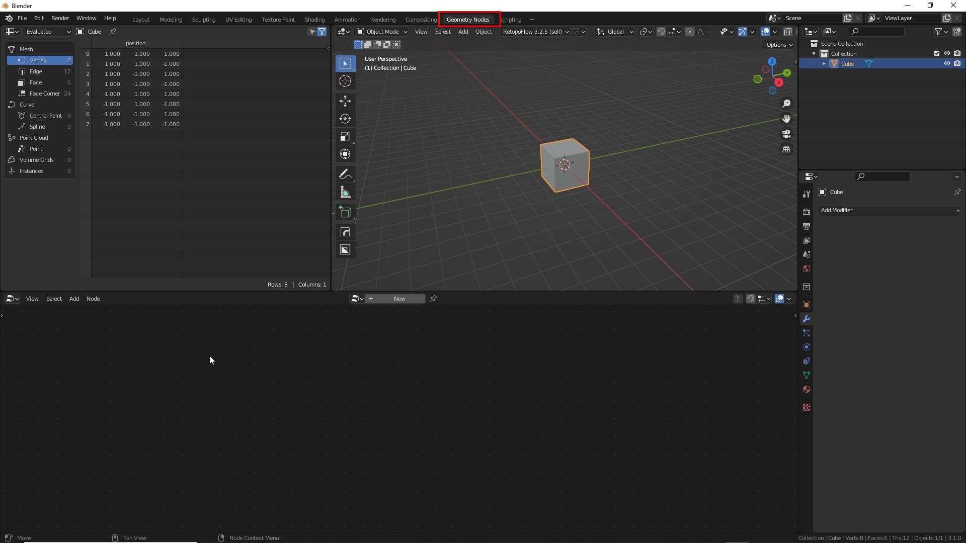
Geometry Nodes Workspace
Select the object to which you want to add a node and click New.
The node is now displayed.
Click on New
Delete one Group Input and add Mesh Primitives→Ico Sphere by pressing Shift+[A].
![Shift+[A]でMesh Primitives→Ico Sphere](https://styly.cc/wp-content/uploads/2022/04/5e.png)
Shift+[A]→Mesh Primitives→Ico Sphere
You can also search for a node using the Search feature at the top of the window which appears by pressing Shift+[A]
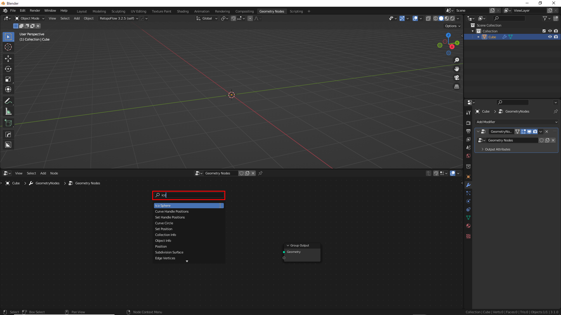
You can search for nodes with Search
Connecting Ico Sphere and Group Output changes the Cube into an Ico Sphere.
Now, set the value of Subdivisions to 4.
Set the value of Subdivisions to 4
Then press Shift+[A] to add Geometry→Merge by Distance.
Dragging a node between the connected nodes will automatically connect them.
![Shift+[A]でGeometry→Mergr by Distanceを追加します](https://styly.cc/wp-content/uploads/2022/04/8-1.gif)
Shift+[A] to add Geometry→Merge by Distance
Add Utilities→Random Value node and change the Data Type to Boolean.
Changing this value changes the number of vertices and edges of the mesh.
In this case, it acts like a Decimate modifier.
Connect the Value of Random Value to the Selection of Merge by Distance.
Change Data Type to Boolean
Add Mesh→Subdivide Mesh, and drag it between Merge by Distance and Group Output.
The Subdivide Mesh node has the ability to partially complete the gaps in the mesh.
Drag between Merge by Distance and Group Output
Add Mesh→Triangulate, and drag it between Subdivide Mesh and Group Output.
The Triangulate node can transform all the faces of the mesh into triangles.
Add Mesh→Triangulate
Add Mesh→Dual Mesh, and drag it between Triangulate and Group Output.
The Dual Mesh node converts faces to vertices and vertices to faces.
This feature creates gaps where vertices are densely packed.
Add Mesh→Dual Mesh
This completes the basic node.
Now, add the Wireframe and Subdivision Surface modifiers.
Make sure the order of the modifiers is: Geometry Nodes, Wireframe, and Subdivision Surface from the top down.
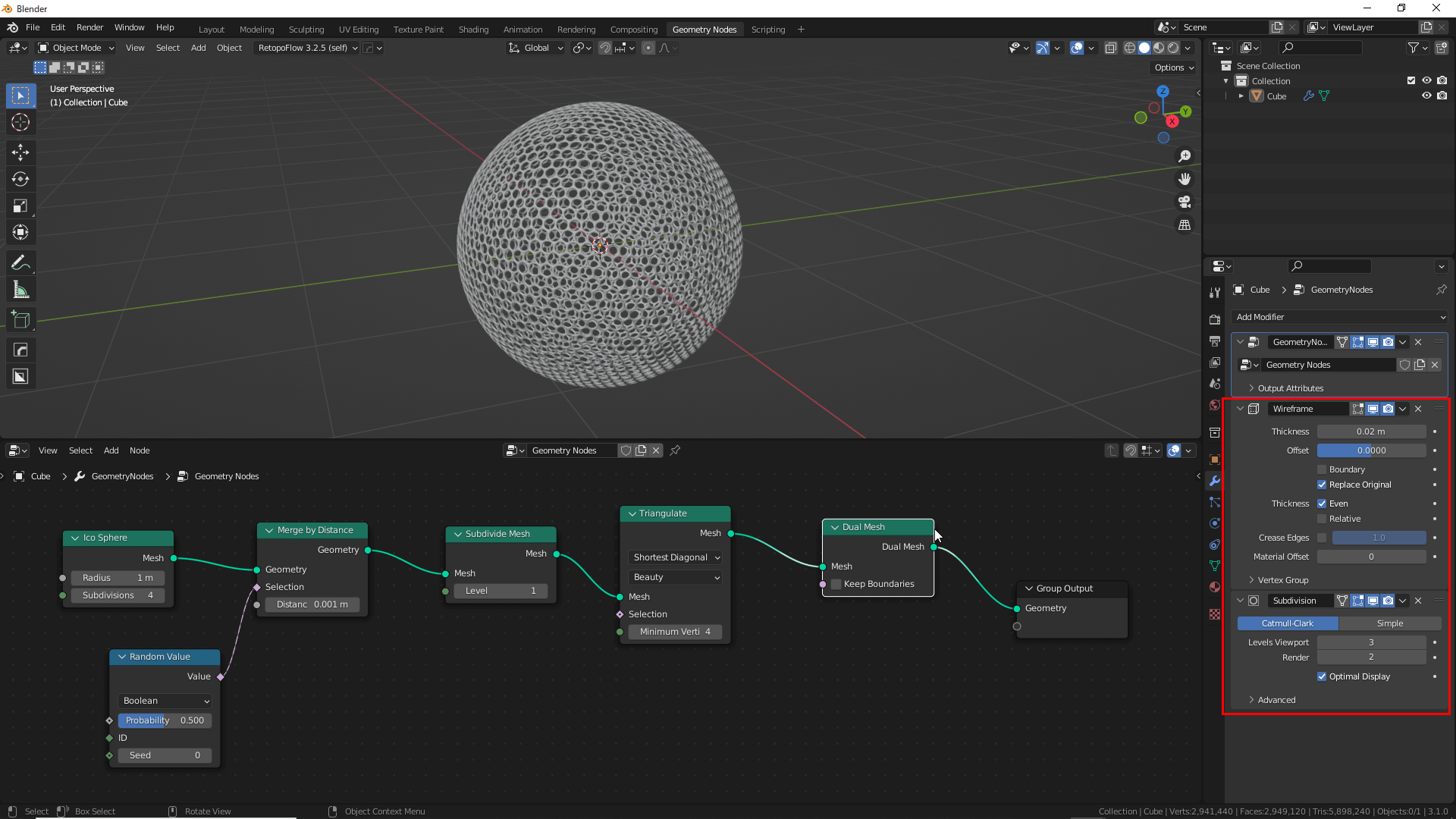
Geometry Nodes, Wireframe, and Subdivision Surface from the Top down
A Subdivision Surface value of 2-3 is appropriate, depending on the performance of the PC being used.
Adding a modifier produces a reticulated sphere.
Change the Shape by Changing the Numerical Value
From here, the shape of the object is changed by changing the value of the Geometry Nodes.
It is recommended that the Subdivision Surface modifier be hidden, as it becomes slow while changing the values.
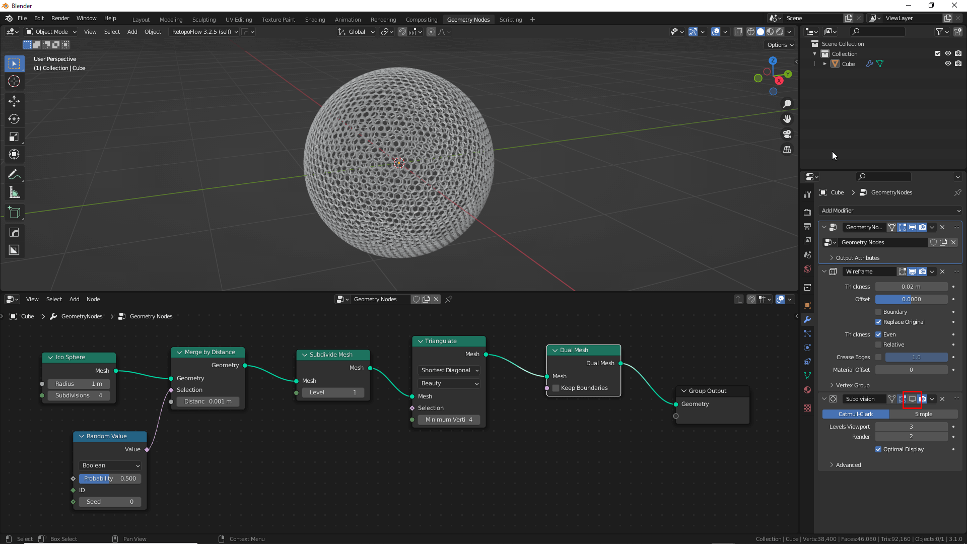
Hide Subdivision Surface modifier
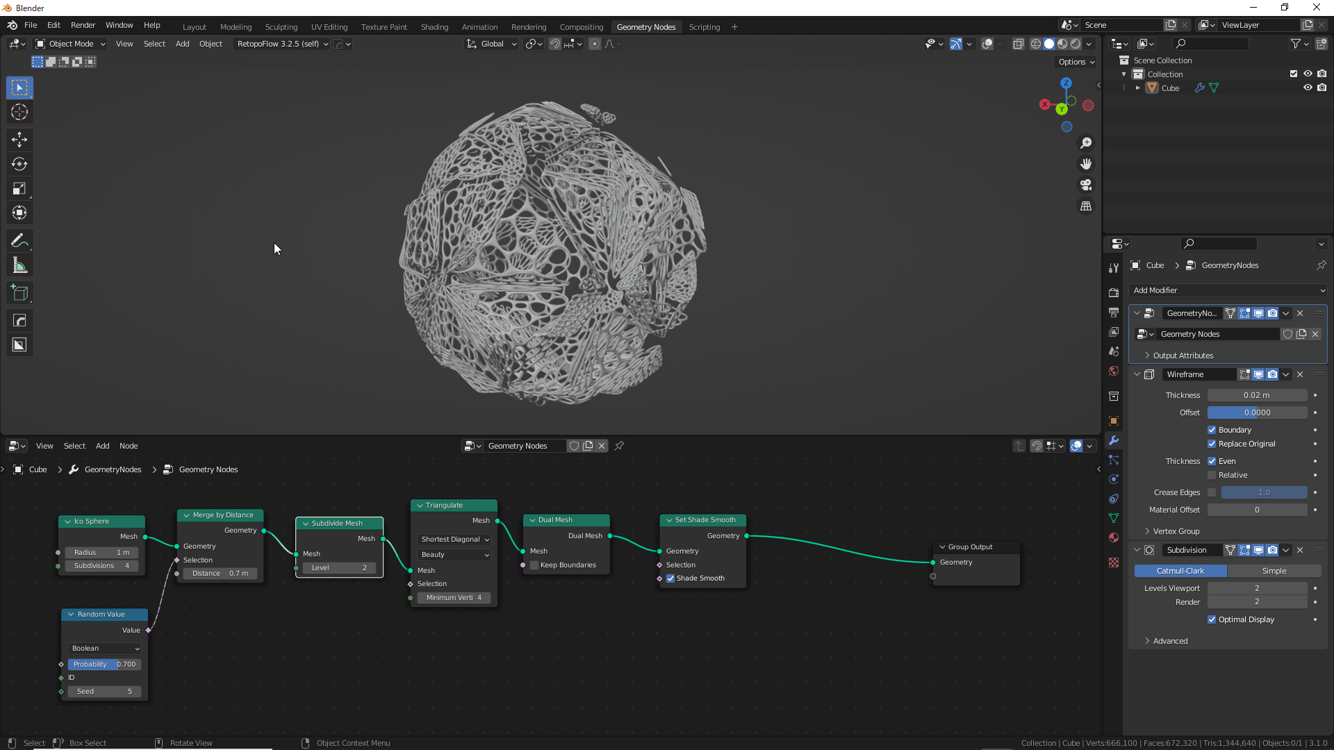
Now, let’s try changing both the Merge by Distance value to 0.7 and the Random Value value to 0.7.
The structure is now random and organic.
Basically, change the shape by changing the value of these two nodes.
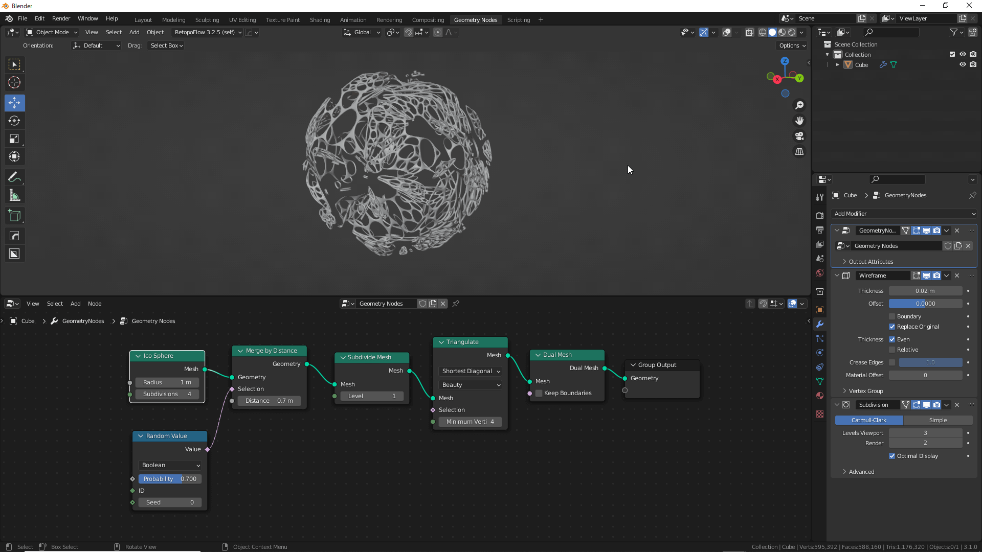
Merge by Distance and Random Value values at 0.7

Hide Subdivision Surface
The randomness of the object can also be changed by changing the Seed value in the Random Value node.
Change the Seed Value
If you look closely at the object, you will notice that there are some hollow areas. These can be filled in by checking the Boundary checkbox in the Wireframe modifier.
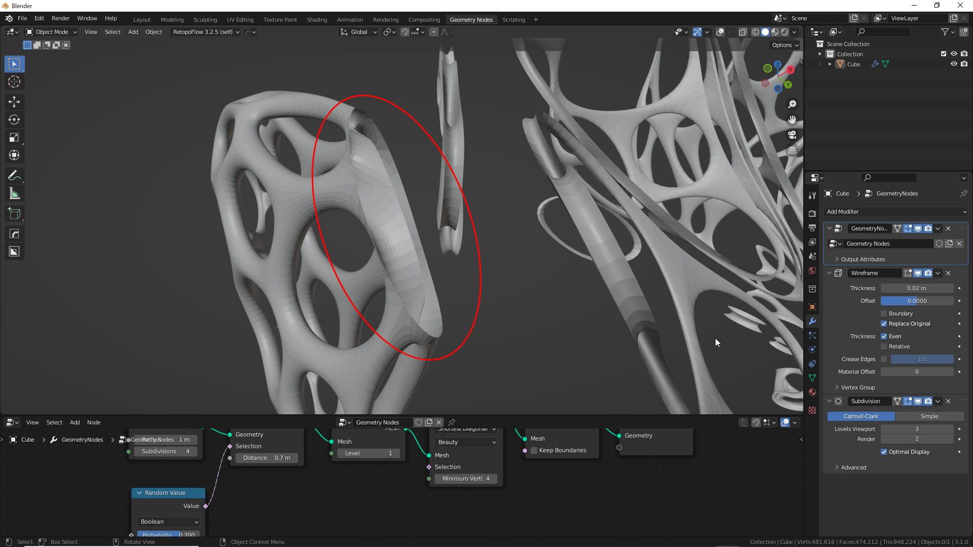
Hollow in Some Areas
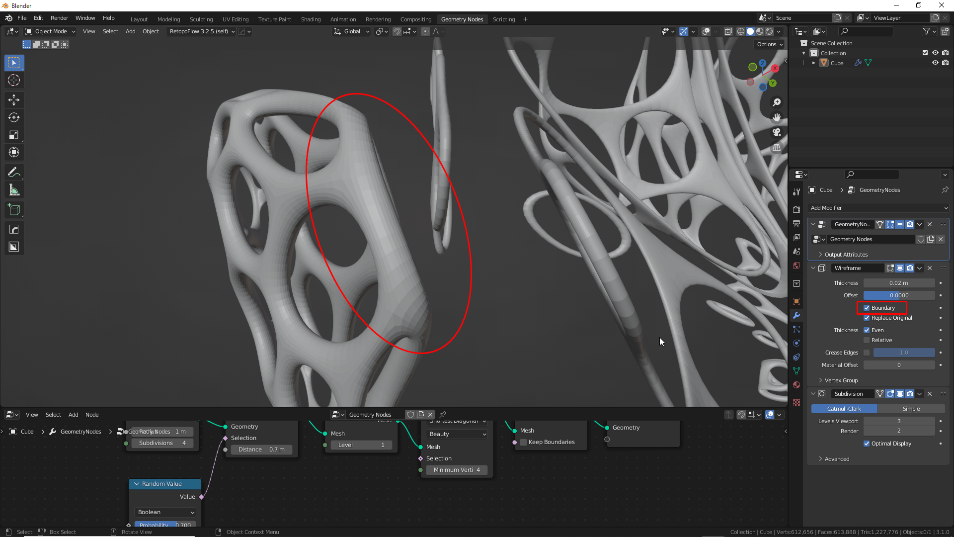
Check the Boundary Checkbox in the Wireframe Modifier
The object’s surface is still not smooth, so add Mesh→Set Shade Smooth, and drag it between Dual Mesh and Group Output.
The surface is now smooth.
Add Mesh→Set Shade Smooth
Next, let’s duplicate the Subdivide Mesh node.
Select Subdivide Mesh, and press Shift+[D] to duplicate the node.
![Shift+[D]でノードを複製できます](https://styly.cc/wp-content/uploads/2022/04/21.gif)
You can Duplicate a Node by Pressing Shift+[D]
Drag the duplicated node between the Set Shade Smooth node and the Group Output.
The gap between the objects is now minimized.
The Effect Depends on Where the Node is Inserted
Changing the value of an existing Subdivide Mesh will cause a similar change, but the gap between the entire object will be refined, so use according to your preference.
Changing the Subdivide Mesh Value also Refines the Mesh
Apply to Other Meshes
This node tree can also be connected to another Primitive Mesh Node to create a different shape.
Add Mesh Primitives→Cone, and replace it with the Sphere node.
Apply to Other Primitive Mesh Nodes
Connecting modifiers and nodes with different values, as shown in the image below, creates an abstract shape that is based on a cone.
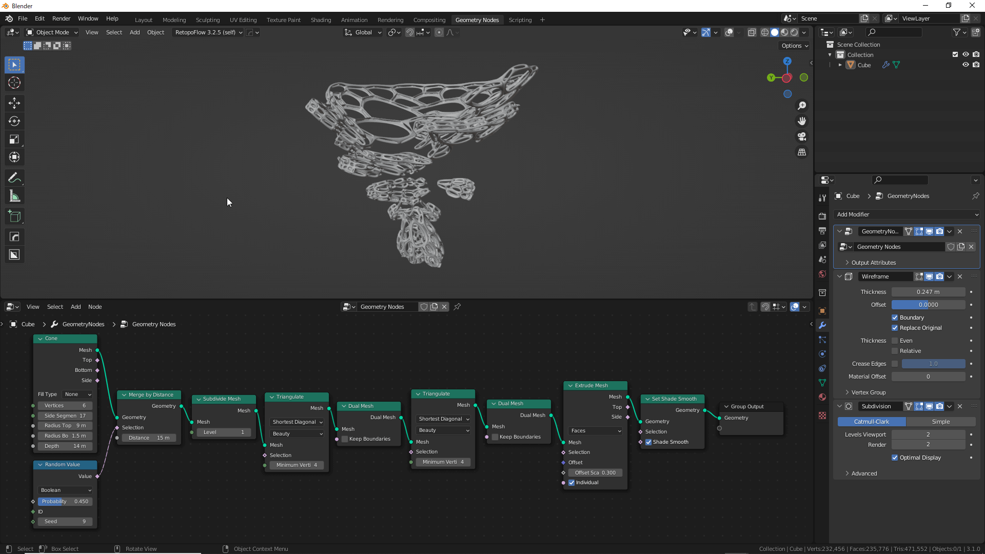
An Abstract Shape has been Created
Other nodes can be reordered and combined to create not only abstract objects but also parametric design-style objects.
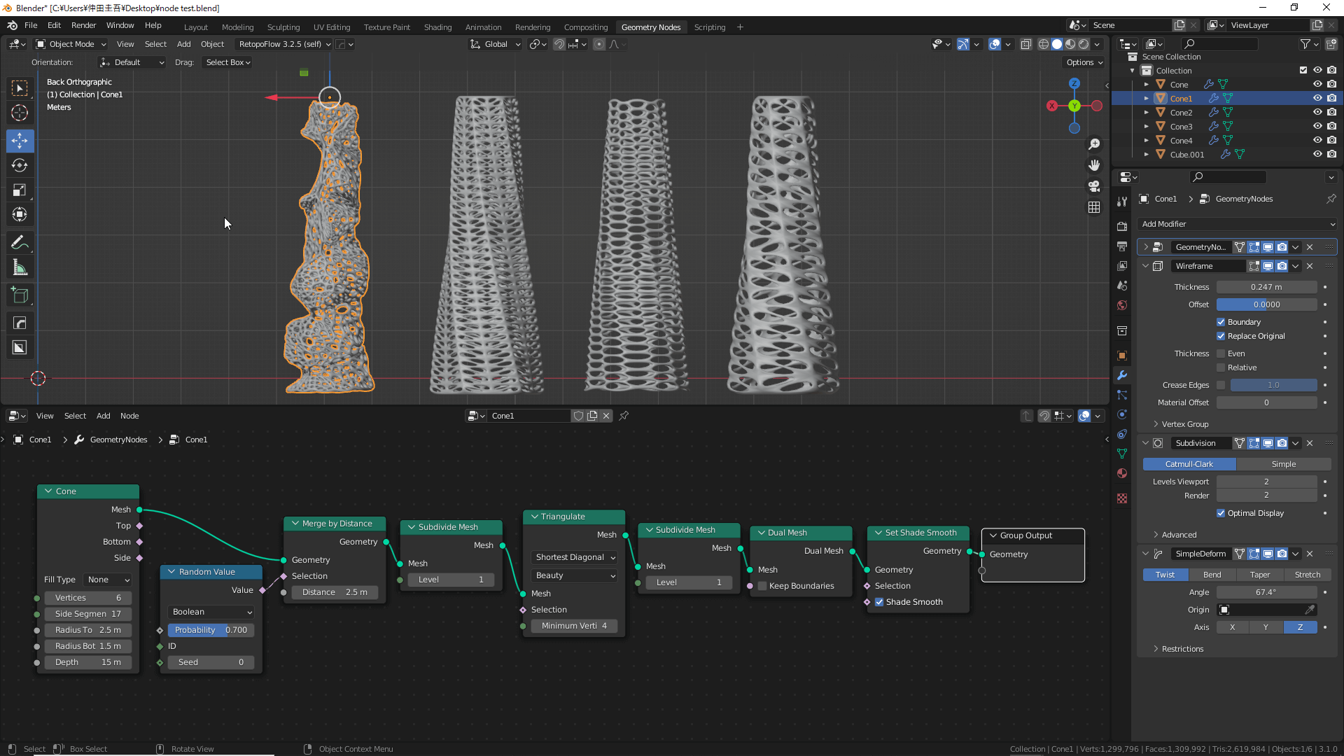
1
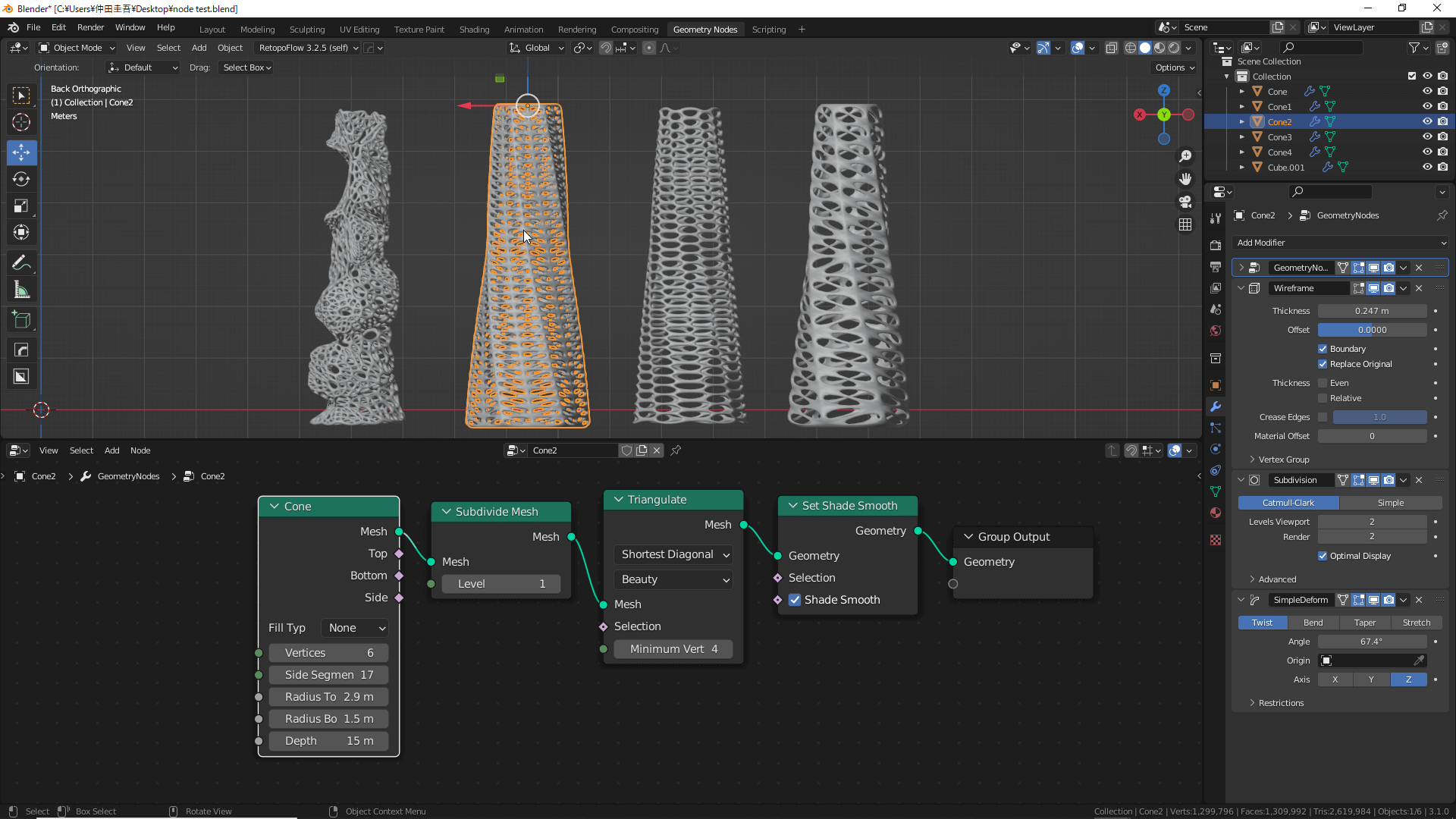
2
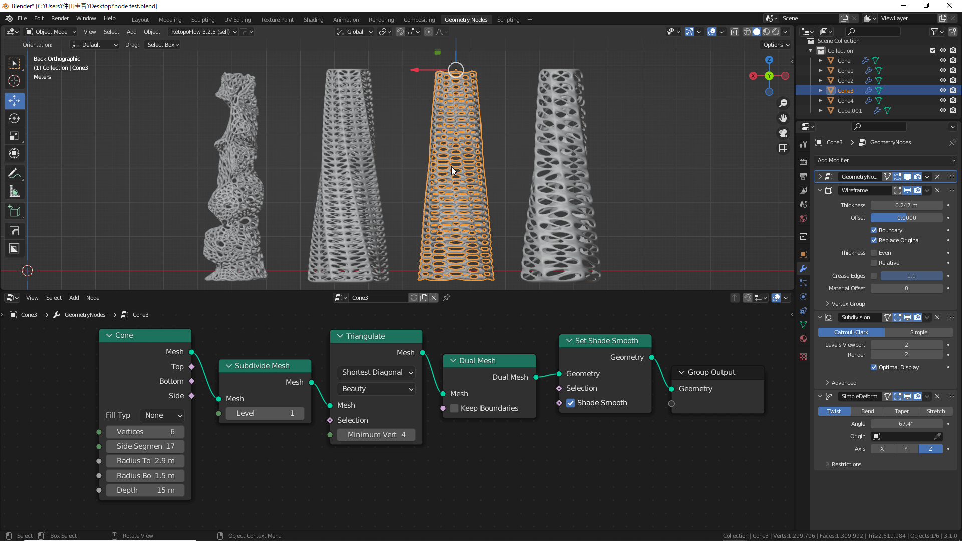
3
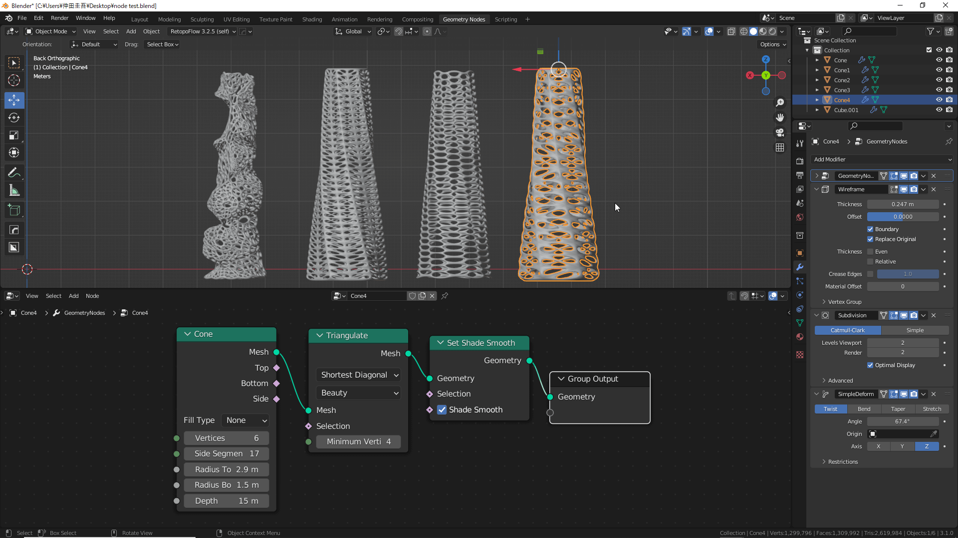
4
How to Export
Return to the Layout window and press Shift+[D] to duplicate the object so that the geometry node information can be edited later.
![Shift+[D]でオブジェクトを複製します](https://styly.cc/wp-content/uploads/2022/04/30.gif)
Press Shift+[D] to Duplicate an Object
Right-click on the object, and select Convert To→Mesh to apply the geometry nodes and modifiers to the original mesh.
Select Convert To→Mesh
Once applied, select the object, and choose File→Export→FBX.
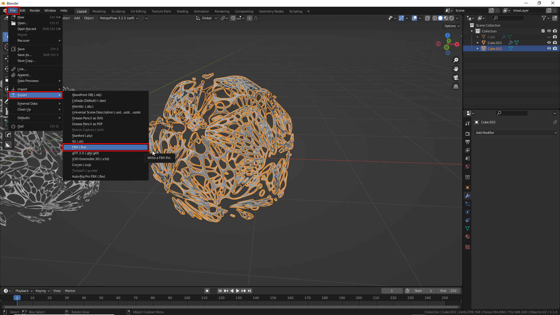
Select File→Export→FBX
Once selected, as shown in the red circled area of the image, select Export FBX.
The export is now complete.
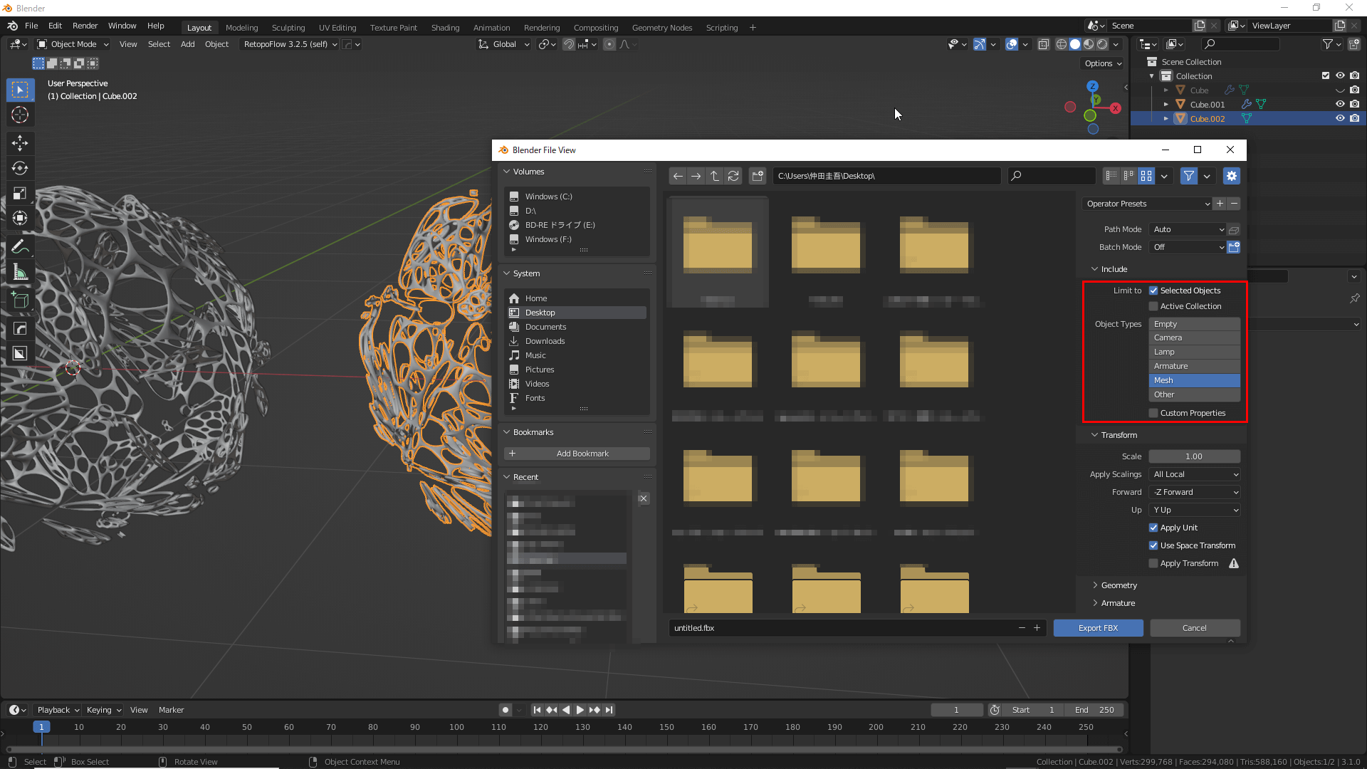
Select Export FBX
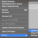
How to Upload to STYLY
How to create an account:

How to upload to STYLY:
How to upload from Unity to STYLY:
Once the 3D model is placed as an object, it will appear as shown below.
This completes the upload to STYLY.
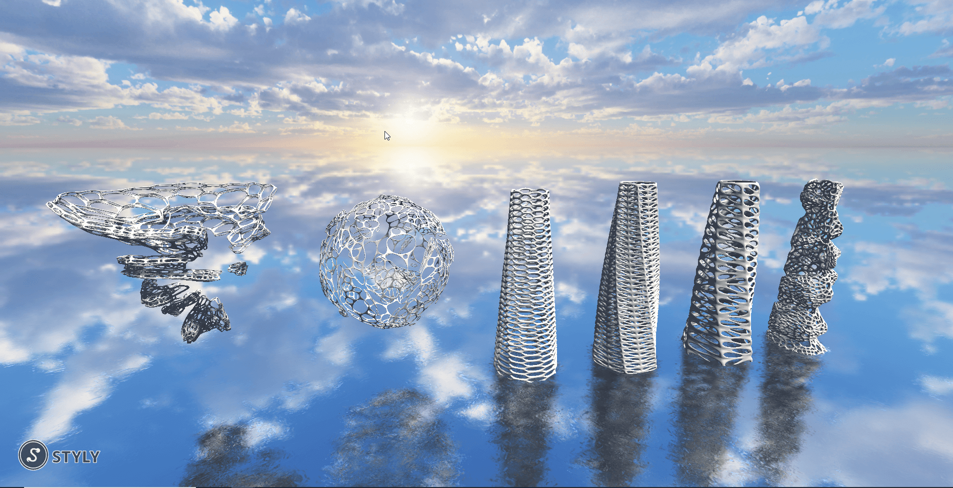
A scene on STYLY