This article introduces the use of Tissue Tools, a standard add-on for Blender.
Tissue Tools has a wide variety of functions, but in this article we will explain how to use the main functions, Tessellate, Dual Mesh, and Weight Tools.
Introduction
Tissue Tools can be used with Blender 3.0, but we recommend using it with Blender 3.1 because it has fewer features and is unstable.
Type Tissue in the search tab under Edit→Preferences→Add ons, and you will see an add-on called Mesh:Tissue and put a check mark in the box.
Check the add-on Mesh:Tissue in Preferences
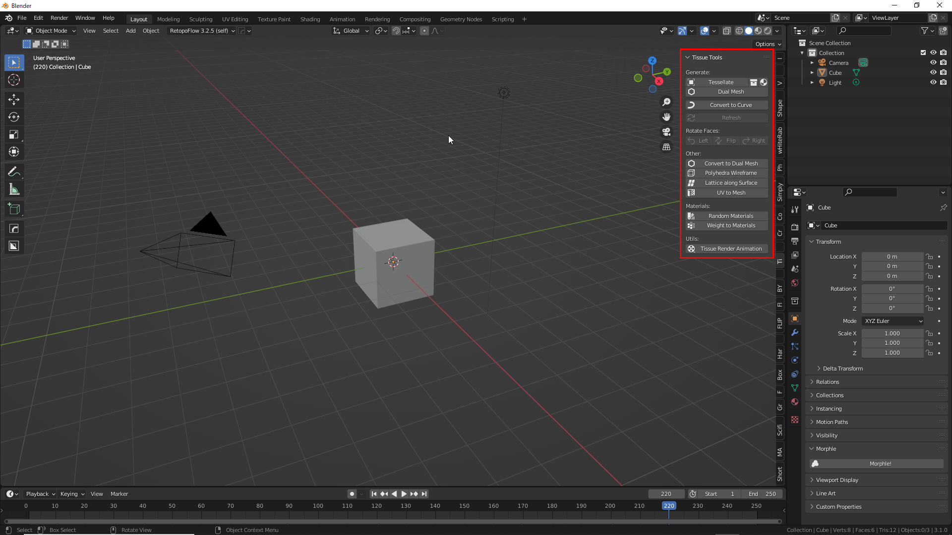
TessellateTools
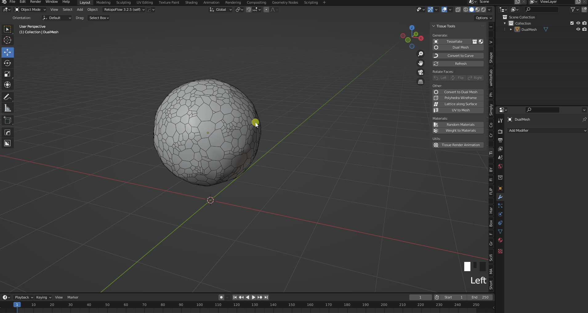
The Tessellate tool duplicates and pastes the selected object (Component) to all faces of the active object (Base).
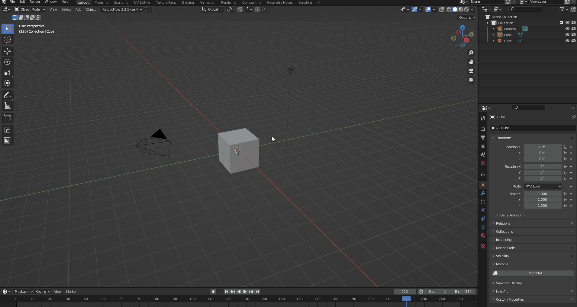
Press the [N] key to display the sidebar and the Tissue Tools tab will appear. It is recommended to display it at all times as it is used frequently.
The Tissue Tools tab appears.
To use the Tessellate tool, you need two objects, so here we have a Cube and a Torus.
![Shift+[A] to add an object](https://styly.cc/wp-content/uploads/2022/04/2.png)
Shift+[A] to add an object
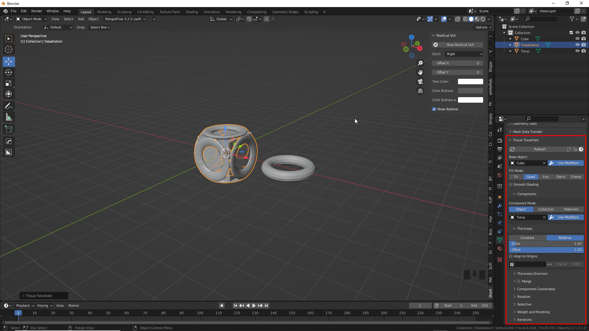
Select objects in the order Torus(Component) → Cube(Base) and press the Tessellate button.
Let’s leave the default settings here and press OK; we recommend saving frequently, as too many faces of the Base object will slow down the operation.

Press the Tessellate button.
Torus is now attached to all surfaces of the Cube. This is the basic function of Tessellate.
Detailed settings can be changed and updated from the Object Data Properties even after Tessellate has been applied.
Here are the main items used.
Object Data Properties
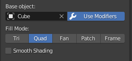
Fill mode allows you to select the shape of the Base when mapping it to the Component object.
Fill mode
- Tri:Automatically divides the faces of the Base object into triangles and assigns Component objects to the triangular faces.
- Quad:Assign a Component object to the quad of a Base object. This is the most basic form.
- Fan:Divide each side of all faces of the Base object into triangles connected to its center.
- Patch:Basically the same as Quad, but suited for curved surfaces such as subdivision surfaces.
- Frame:Component objects can be applied along surfaces of a specific thickness.
Component mode allows you to select where to place the component object.
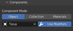
Component mode
- Object:Attach Component objects to all faces of the selected Base object.
- Collection:Assigns objects contained in the selected collection; Component objects are attached randomly by default, but you can also select vertex groups for placement.
- Material:A Component object can be pasted at any position on the Base object by using the same material assigned to the Base object and the same name for the Component object (it is not necessary to use the same material).
Thickness allows you to adjust the scale and offset values of the Component object.
Thickness
- Constant:Paste the Component object with equal thickness in the normal direction.
- Relative:The Component object is pasted onto the Base object with a thickness proportional to the dimensions of the face of the Base object. The aspect ratio will be the same as the original Component object.
- Scale:Adjusts the thickness of the Component object.
- Offset:Adjusts the distance between the faces of the Component object and the Base object.
Examples of Usage
The first step is to add the Extra Object add-on to prepare a component object.
Type “Extra” in the search field of Edit→Preferences→Add ons to see the Add Mesh:Extra Object add-on and put a check mark in the box.
Check the Add Mesh:Extra Object add-on in Preferences
Shift+[A] mesh→Extras→Add Honeycomb.
Once added, go to the AddHoneyComb tab in the lower left corner and set Num of rows to 3.
![Ctrl+[A]→mesh→Extras→Honeycomb](https://styly.cc/wp-content/uploads/2022/04/8.gif)
Added Honeycomb
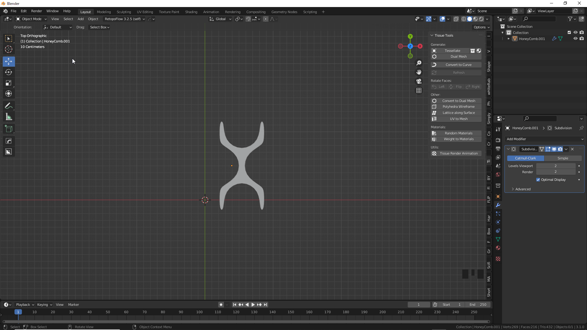
Delete unnecessary areas as shown in the image and set the value of Subdivision Surface to 2.
Delete unnecessary parts
Add Subdivision Surface.
Addition of Subdivision Surface
Apply Subdivision Surface in Object Mode.
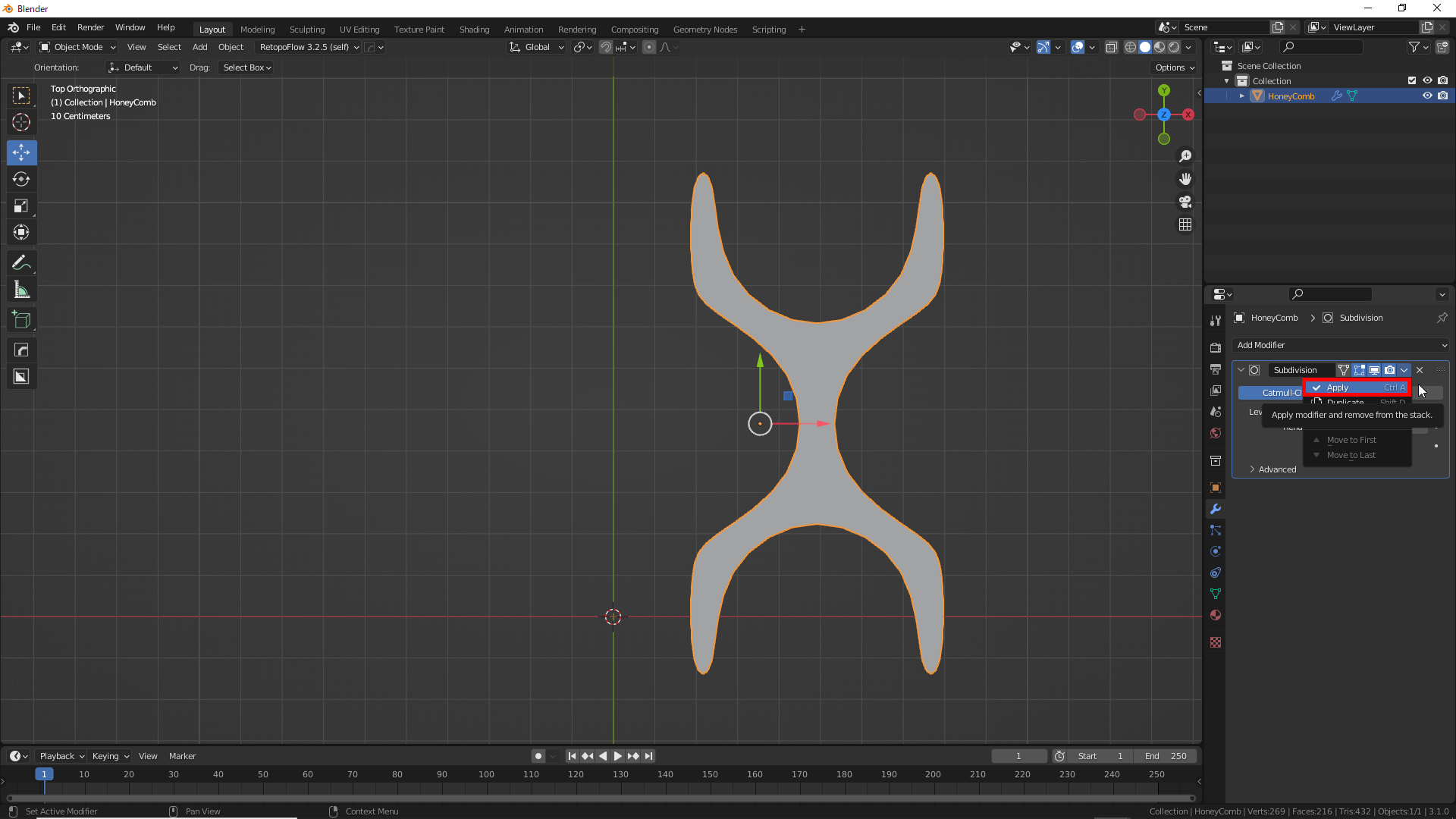
Apply Subdivision Surface
Enlarge the square circled in red until it protrudes a little.
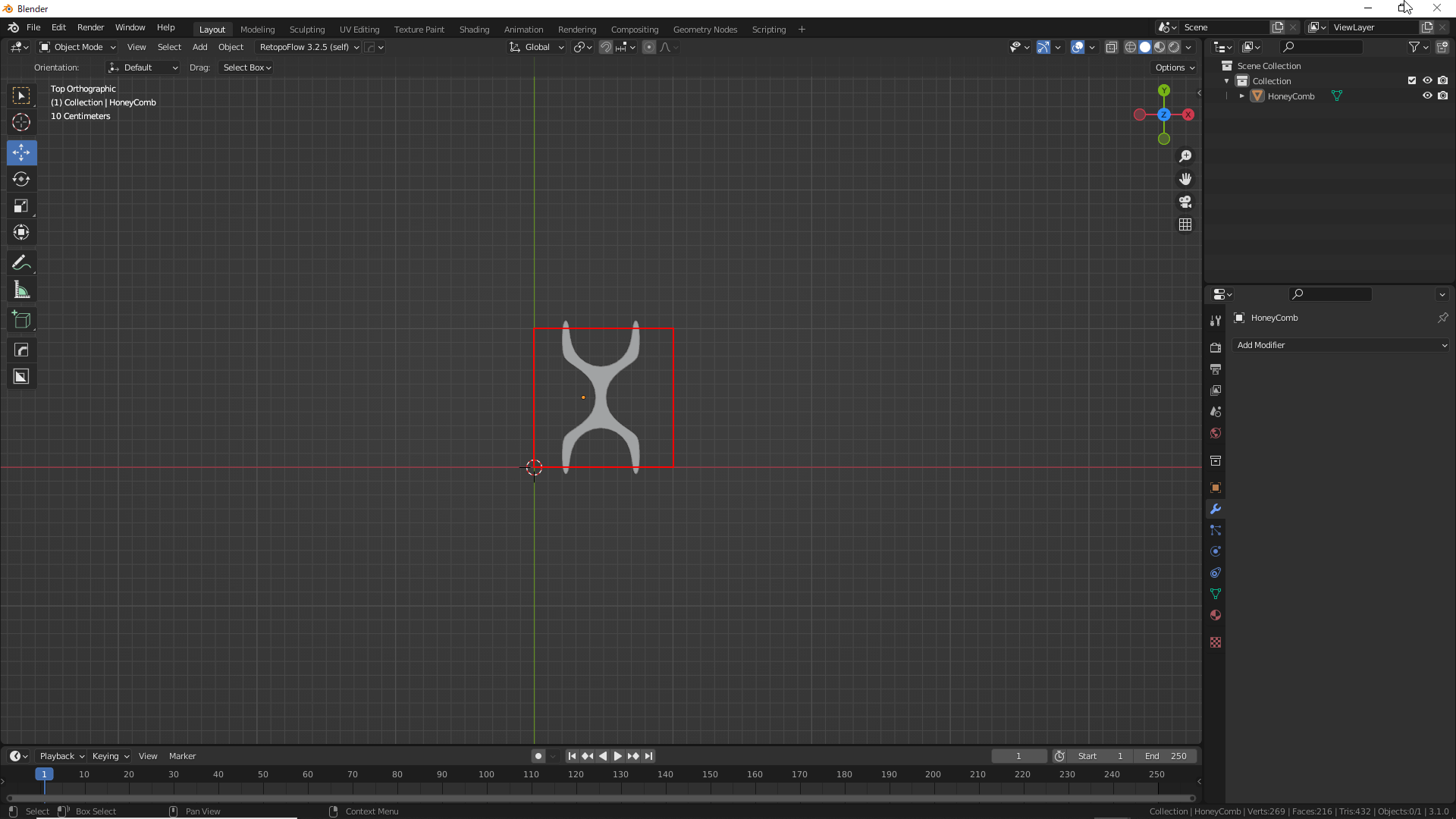
Object Enlargement
In edit mode, press the [K] key to change to the knife tool and cut the outliers from the square. Press the [C] key with the knife tool to cut to the back side.
Preparation of the Component object is complete.

Cut with knife tool
The base object can be any object of your choice, but in this case we will use a Cylinder. The number of sides can be adjusted with the mouse wheel button.

Adjust the number of edges
Since we want the face to be as square as possible, select an edge in edit mode and press Ctrl+[R] to add an edge and delete the top and bottom faces.
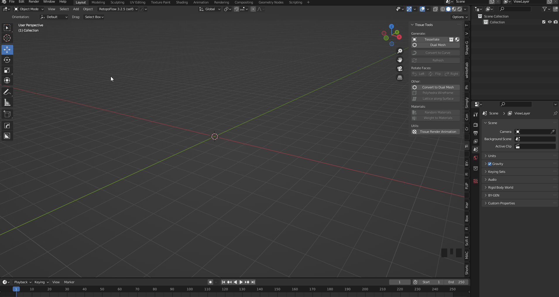
Select Honeycomb(Component), then Cylinder(Base), press Tessellate, and click OK.

Tessellate object is created
We want to add a twist to the net-like object generated by Tessellate (henceforth referred to as “net”), so we add a Simple Deform modifier to the Cylinder.
Once the modifier is added, select the mesh and press Refresh in the Tissue Tools panel.
Any changes made to the Base object will be reflected in the Component object when you press Refresh.

Select Refresh from the Tissue Tools panel
We want to change the angle of the Component object, so we select the net and change the Shift value of Rotation in the Object Data Properties to 1.
You can also randomize the angle of the Component object by selecting Rondam.

Select Rotation from Object Data Properties

Changing the Seed value will change the angle randomly
Thickness can be added by selecting the netting and adding the Solidify modifier.
These are the basic uses of Tessellate.
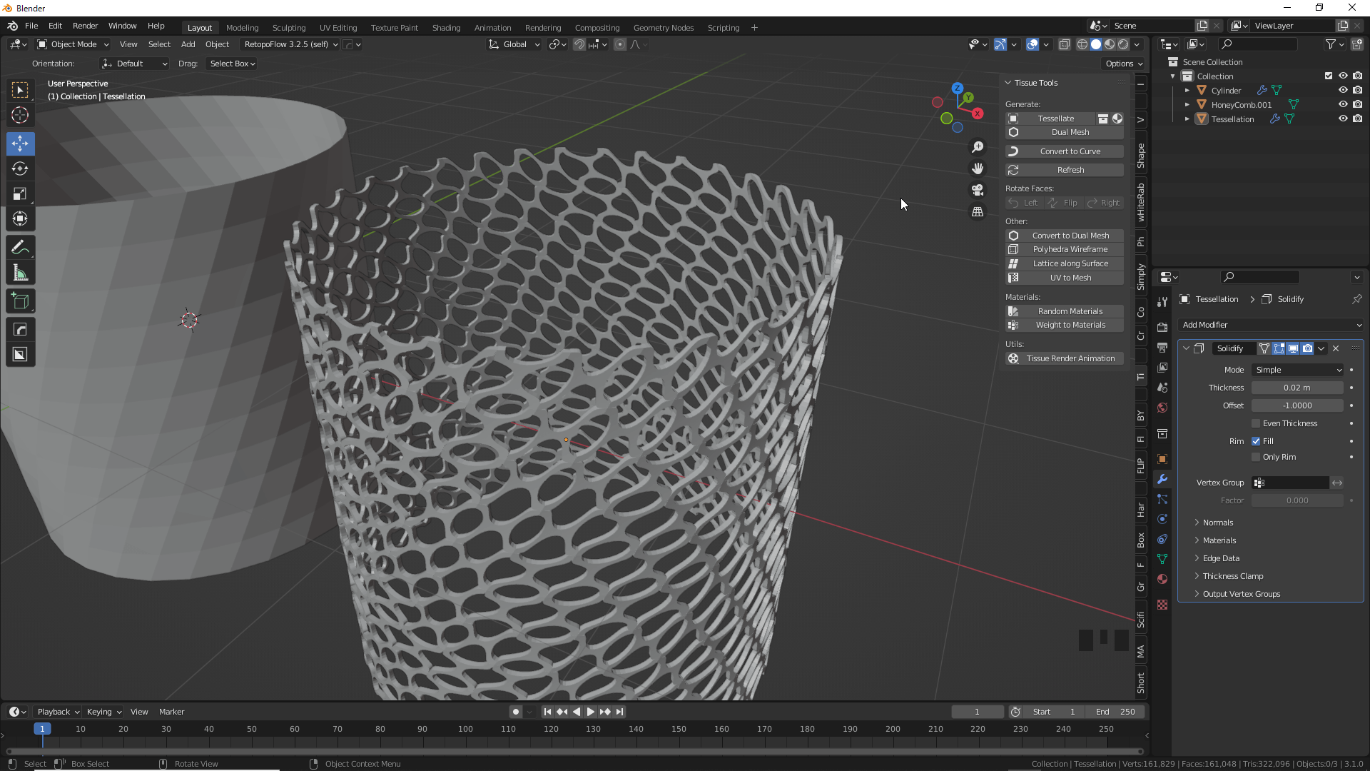
Then you get a sci-fi style mesh like this
Examples of Usage2
Add Torus, the Base object, to the scene by pressing [Ctrl]+[A].
Add the Decimate modifier and Subdivision Surface, and set the Un-Subdivide value to 3 and the Subdivision Surface value to 3.
Check Optimal Display for Subdivision Surface.
(It is better to turn on the Wireframe display for better visibility.
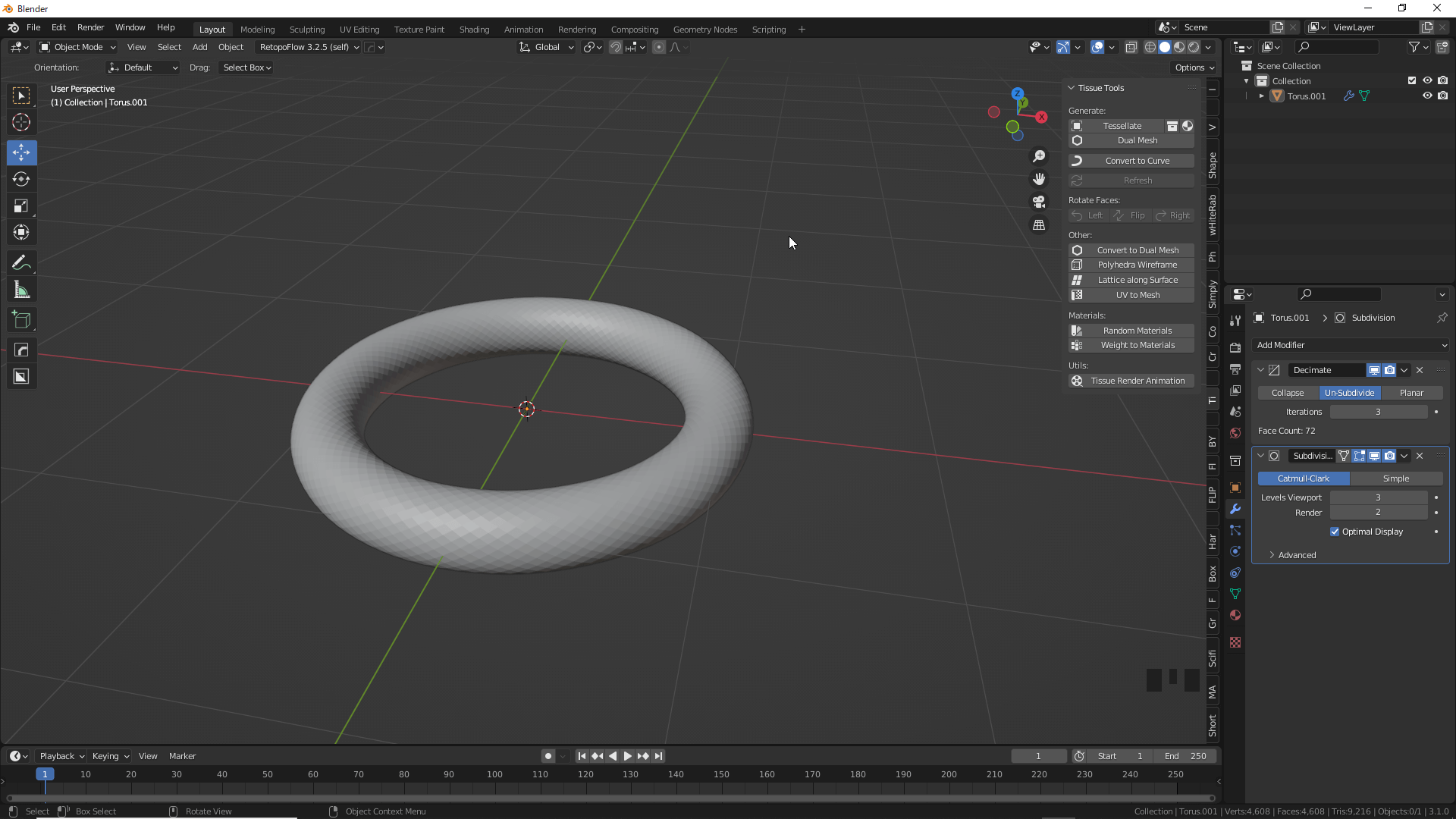
Add Torus to the scene
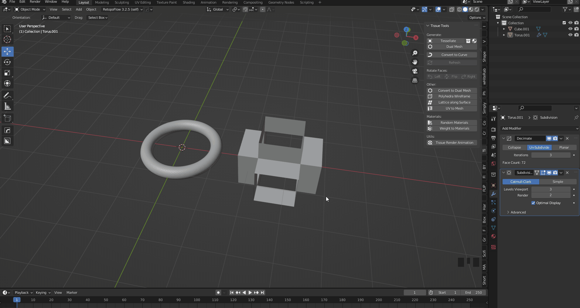
Add a Cube as a component object, select all faces in edit mode, right-click and select Extrude Indivisual Faces to extrude the faces.
Delete the extruded faces before subdividing them.
After deleting the faces, select all the faces, right-click and select Subdivide, and set the value to 3.

Select Extrude Indivisual Faces and extrude the face
Select Cube, then Torus, and press Tessellate.
Select “Patch” for Fill Mode and check “Merge” and “Smooth Shading.
If you do not check the Merge checkbox, each component will be broken up into pieces, but you can set it to your liking as it may result in an interesting shape.
Tessellate the Torus
Select the generated Tessellate object, add a Smooth modifier, and set the Repeat value to 50.
The value of the Smooth modifier is limited by dragging, so enter a numerical value.
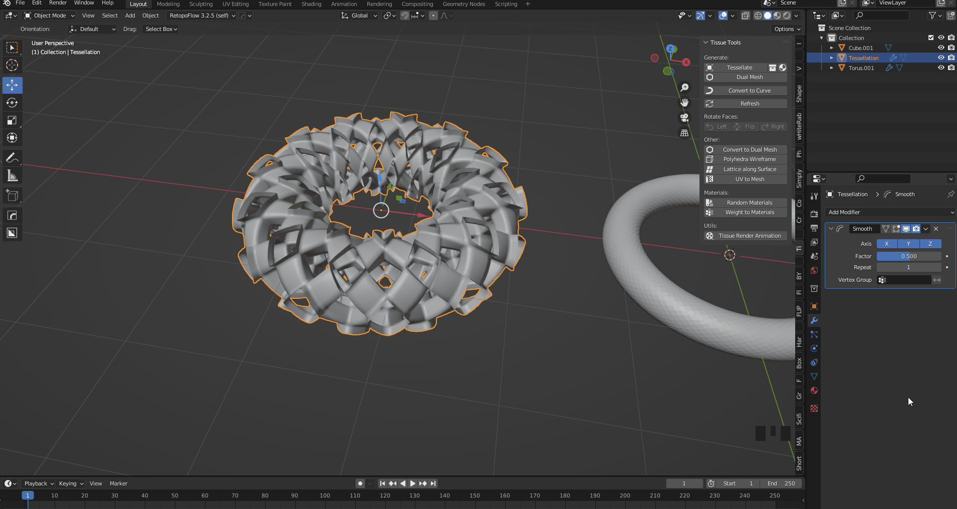
Smooth modifier added
Since there is no thickness, the Solidify modifier is added to add thickness to complete the process.
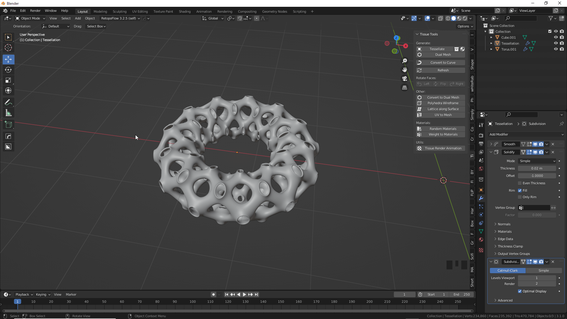
It has taken on an organic form.
Dual Mesh
Dual Mesh creates a dual mesh based on the selected mesh.
The output surface shape can be either triangular or rectangular.
As the Dual Mesh is repeated, the mesh becomes smaller and more distorted.
Be careful not to make it too fine or the Wireframe modifier may not display properly.
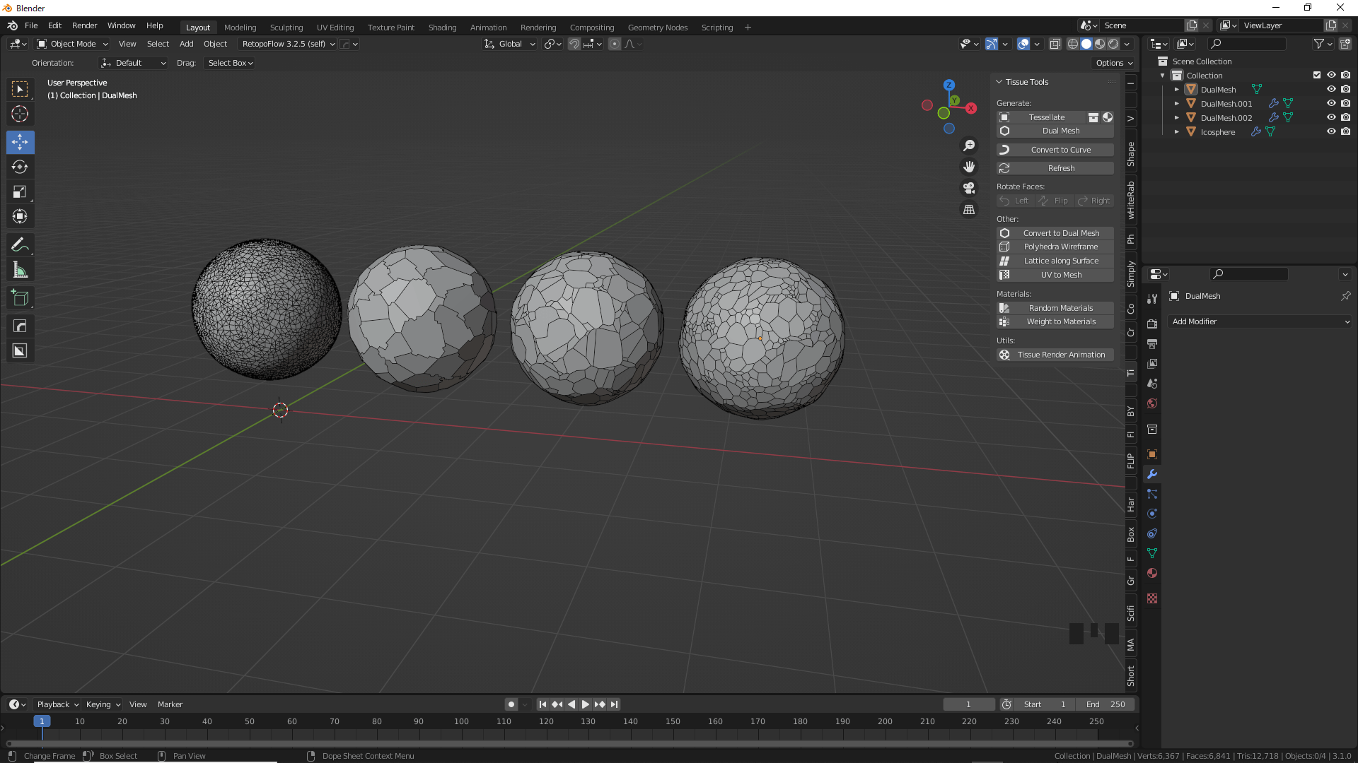
Dual Mesh
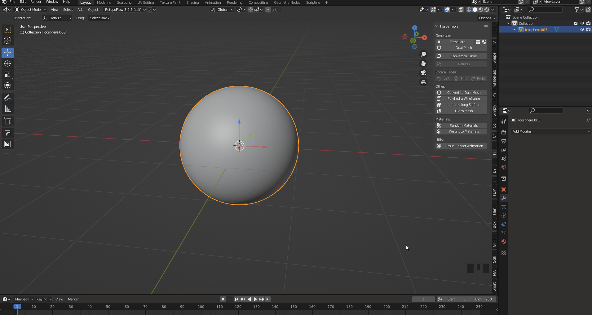
Add an Ico Sphere to the scene.
Add a Subdivision Surface to the Ico Sphere with a value of 4.
Ico Sphere→Subdivision Surface
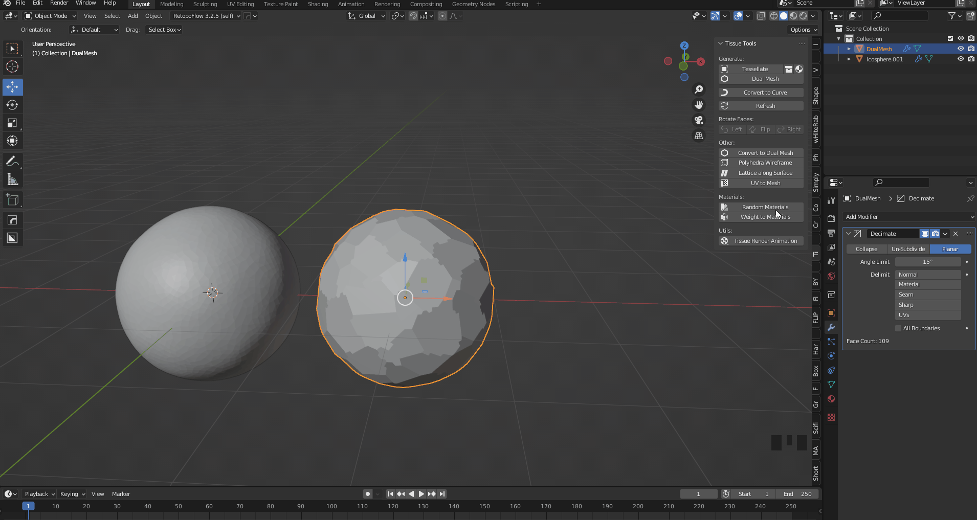
Next, add Decimate and set the value to 0.2.
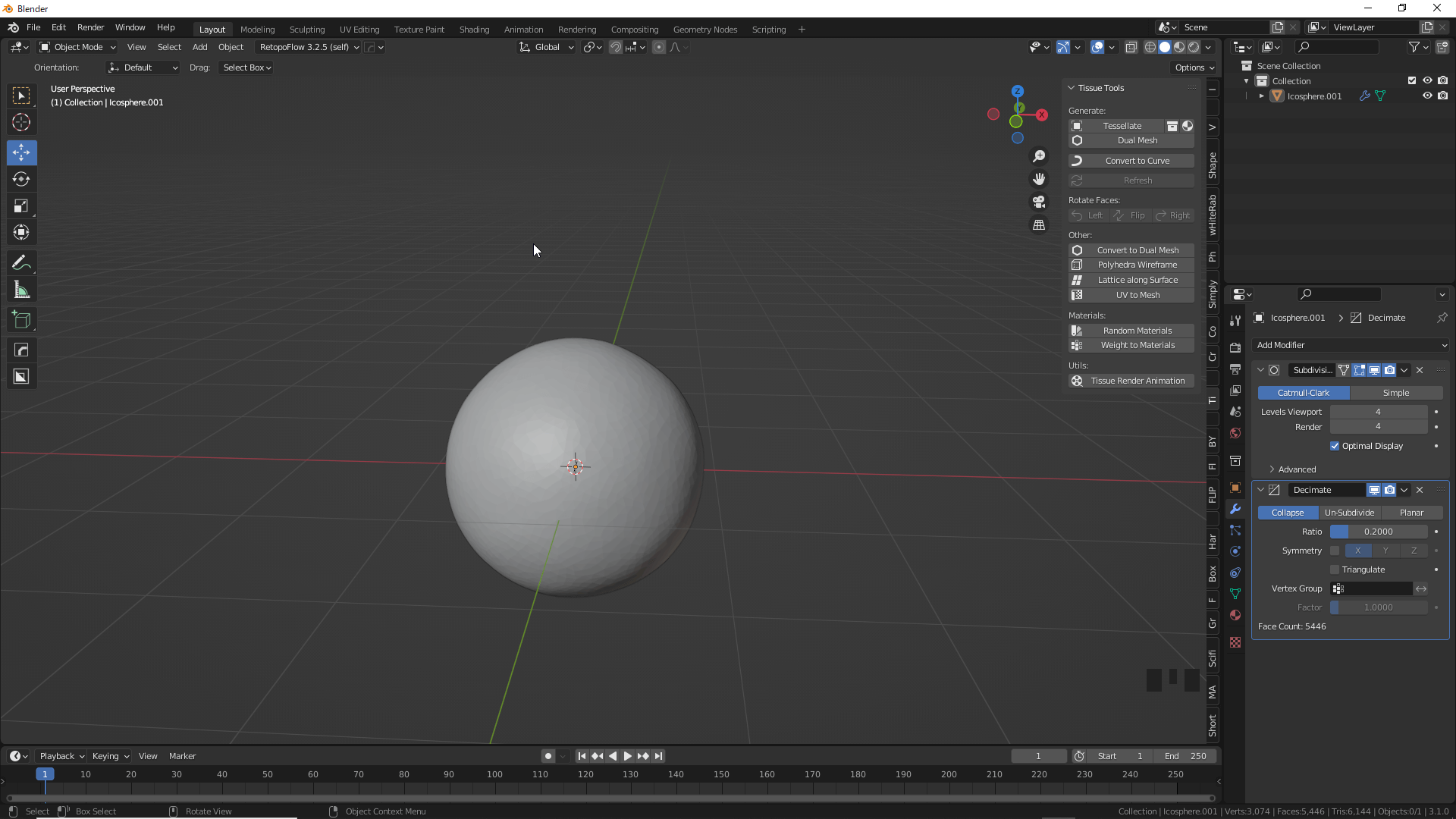
Decimate
Select Ico Sphere and click Dual Mesh→OK.
A dual mesh has been created.

Dual meshes are generated independently
Add Decimate to the created dual mesh and set the Planer angle to 15°.
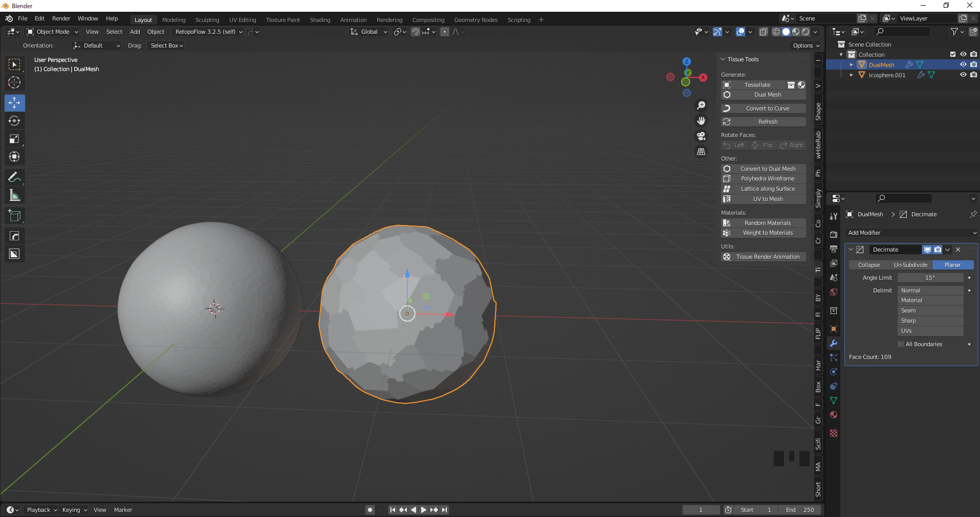
Planer set to 15°.
Then click Dual Mesh→OK again to create a dual mesh.
The shape of the surface will gradually become random, so repeat the above process until the desired shape is achieved.
The shape of the surface gradually becomes more random.
In this case, the following sequence was generated: ICO Sphere→Subdivision Surface4→Decimate(Collapse)0.2→Dual Mesh→Decimate(Planer)15°→Dual Mesh→Decimate(Planer)5°→Dual Mesh Decimate(Planer)5°→Dual Mesh.
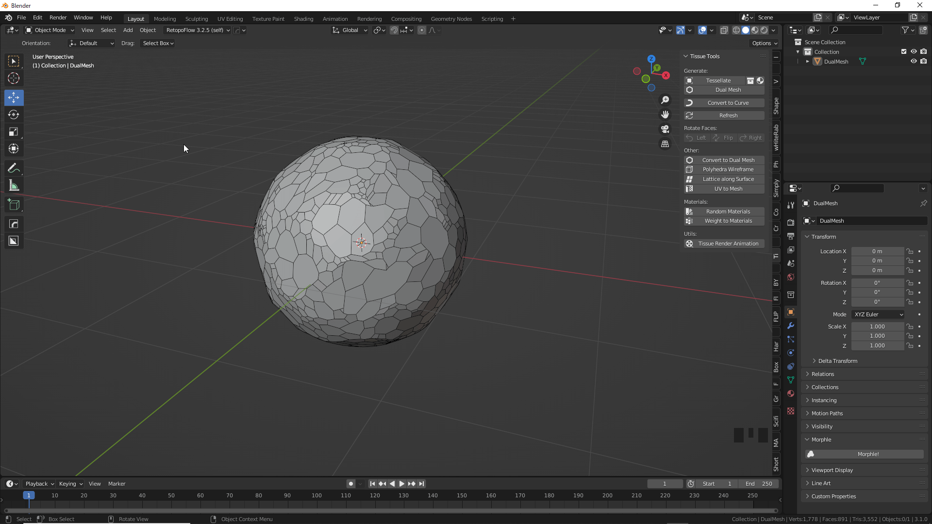
The pattern will be random.
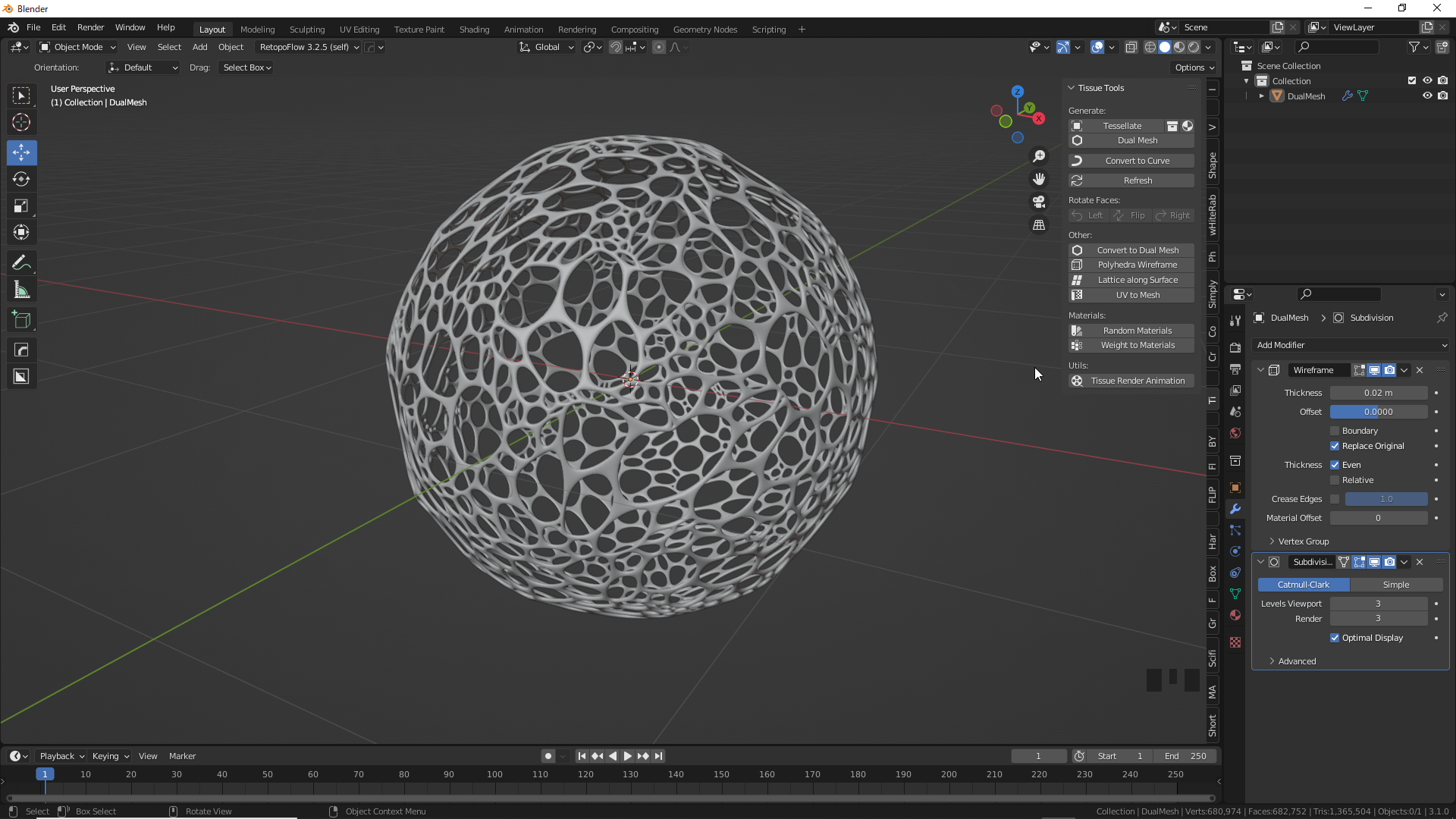
Next, add the Wireframe and Subdivision Surface modifiers to the generated dual mesh.
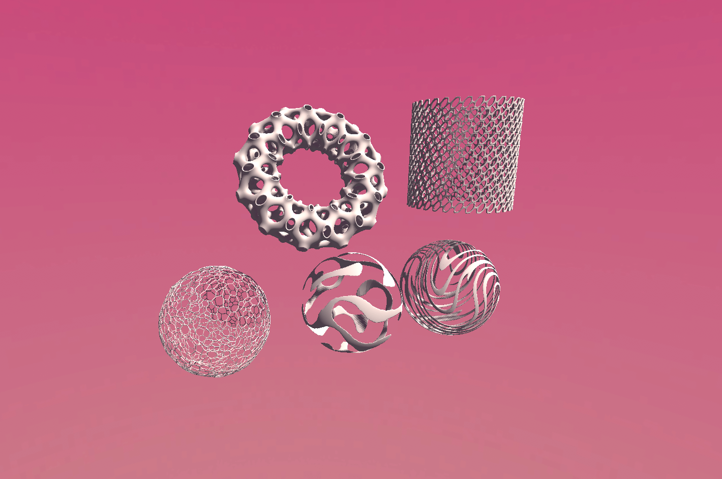
This will result in a Voronoi-like organic object.
It can also be combined with other modifiers such as Simple Deform to create unique shapes.
Thickened and Voronoi shape.
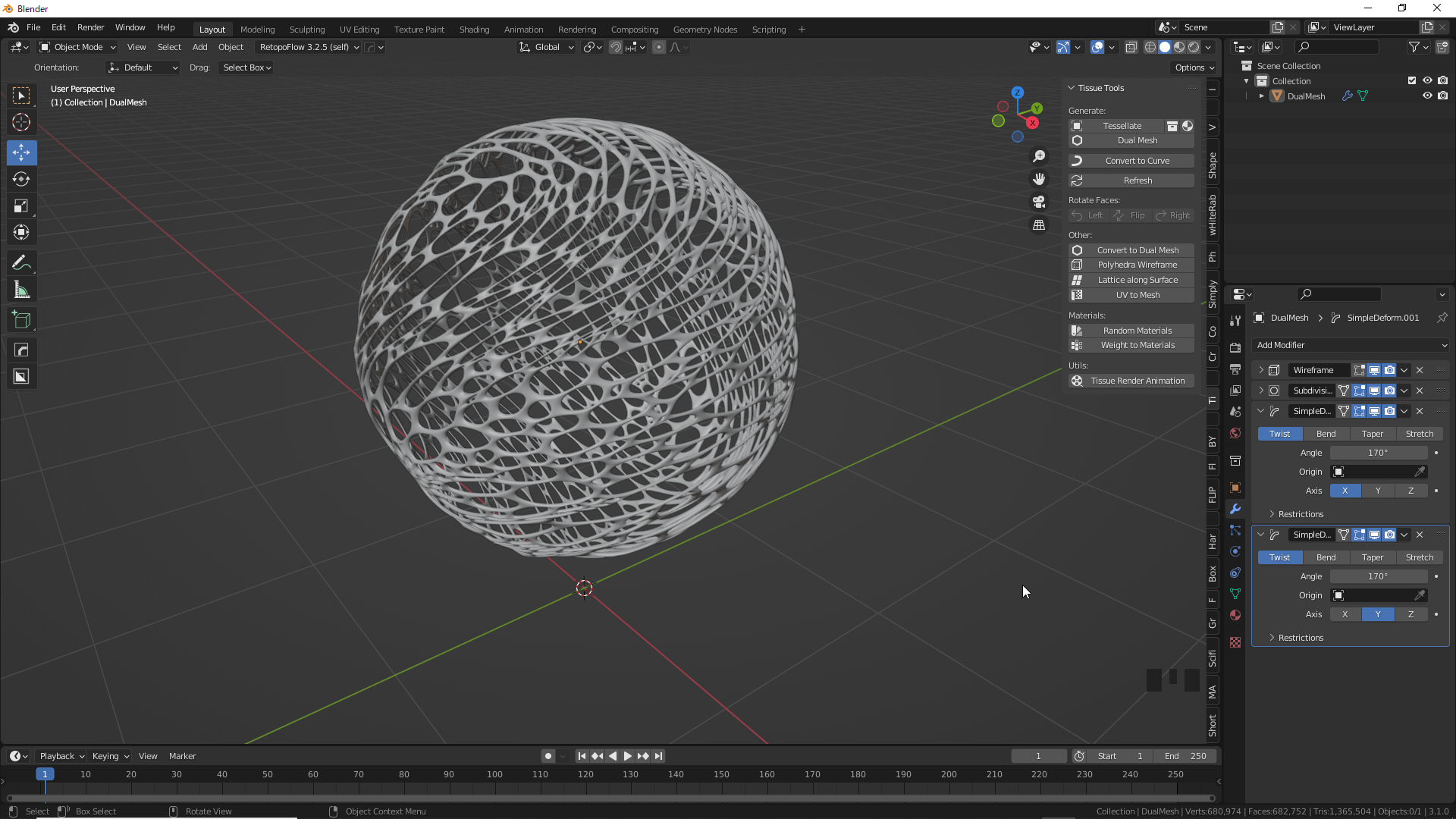
Deformed by Simple Deform modifier
You can convert the edges of an object to a curve by selecting the dual mesh and clicking Convert to Curve in the Tissue Tools tab.
You can add thickness to the curve by changing the value of Object Data Properties→Bevel→Depth.
Convert to Curve→Object Data Properties→Bevel→Depth
Weight Tools
Reaction DIffusion
The Tissue Tool weighting tool uses a type of mathematical model that corresponds to a physical phenomenon called the Reaction DIffusion System.
Simply put, changes in time are caused by diffusion and reaction.
This mechanism is applied to the Weights tool, where larger weights diffuse to smaller weights, causing changes when they interfere with other weights.
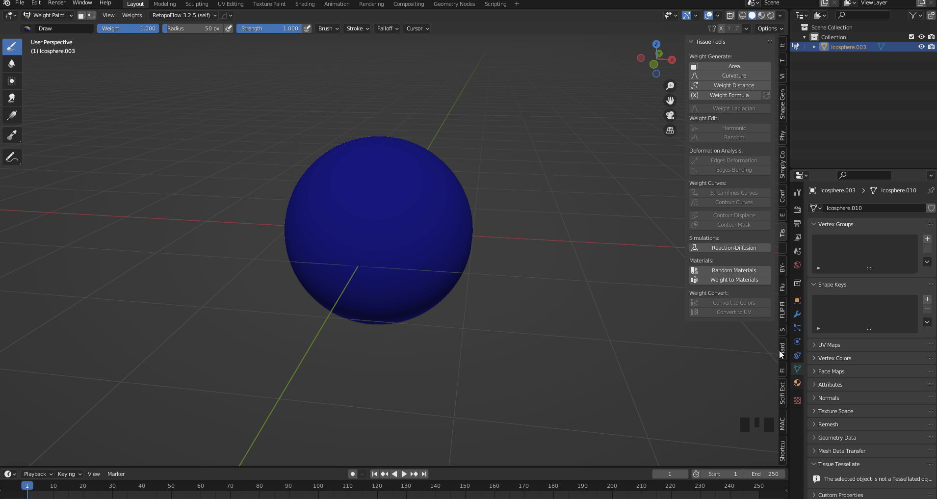
Add an Ico Sphere and set the Subdivide value to 6.
Select Ico Sphere and enter Weight Paint mode.
Translated with www.DeepL.com/Translator (free version)
Weight Paint mode
Click on Reaction DIffusion in the Tissue Tool tab to add Vertex Group AB.
If Vertex Group AB already exists, click the minus button to delete it.
Reaction DIffusion
Paint the weights as you like. You can change the thickness of the brush to create a different pattern.

Weight Paint
When you finish painting and play the animation, the weights will spread and react.
The weights can be applied while the animation is playing.
Reset Reaction DIffusion can be used to reset the pattern.

Weights diffuse and react.
You can adjust the way the weights move by changing the f and k values in the Object Data Properties, but we will leave them at their default values.
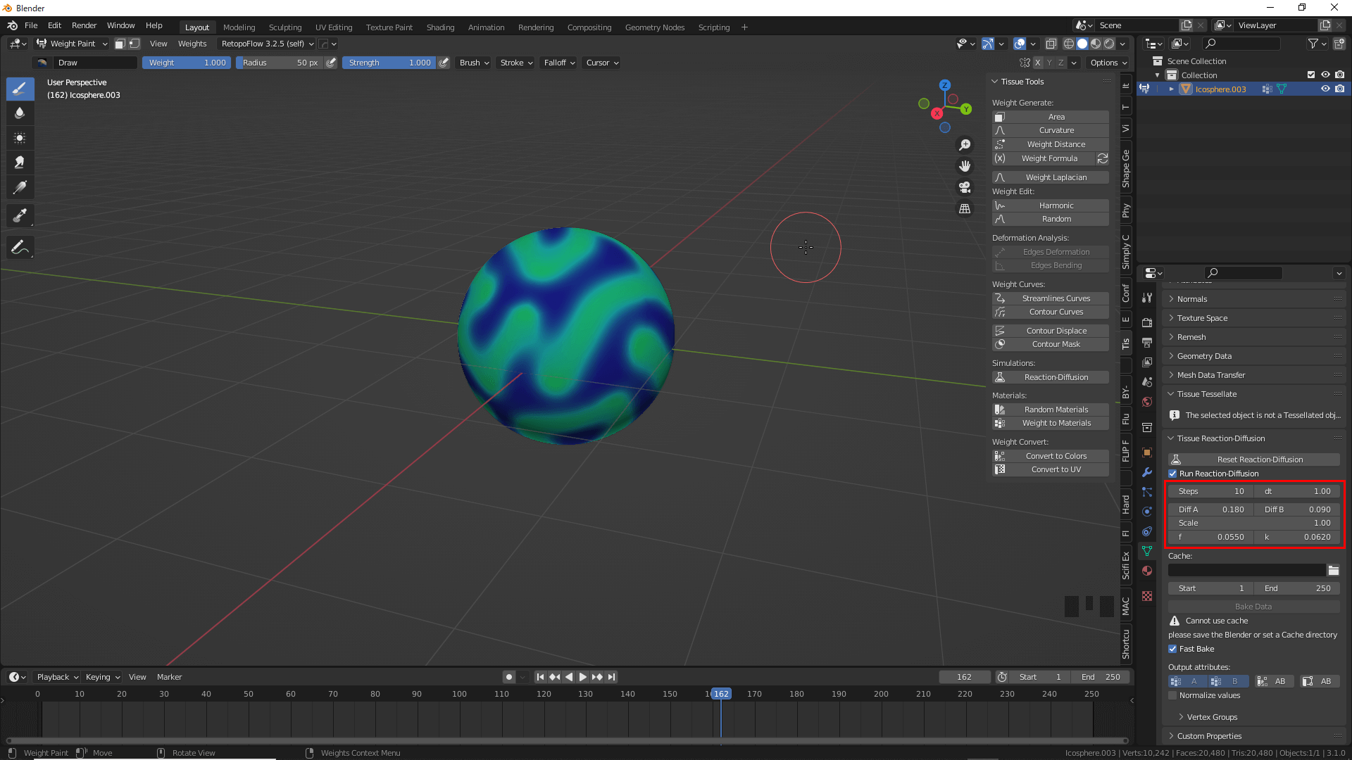
The speed and size of the diffusion can be adjusted.
Stop the animation, return to Object Mode and add a Mask modifier.
Select B for Vertex Group.
Both A and B can be used for Vertex Group.
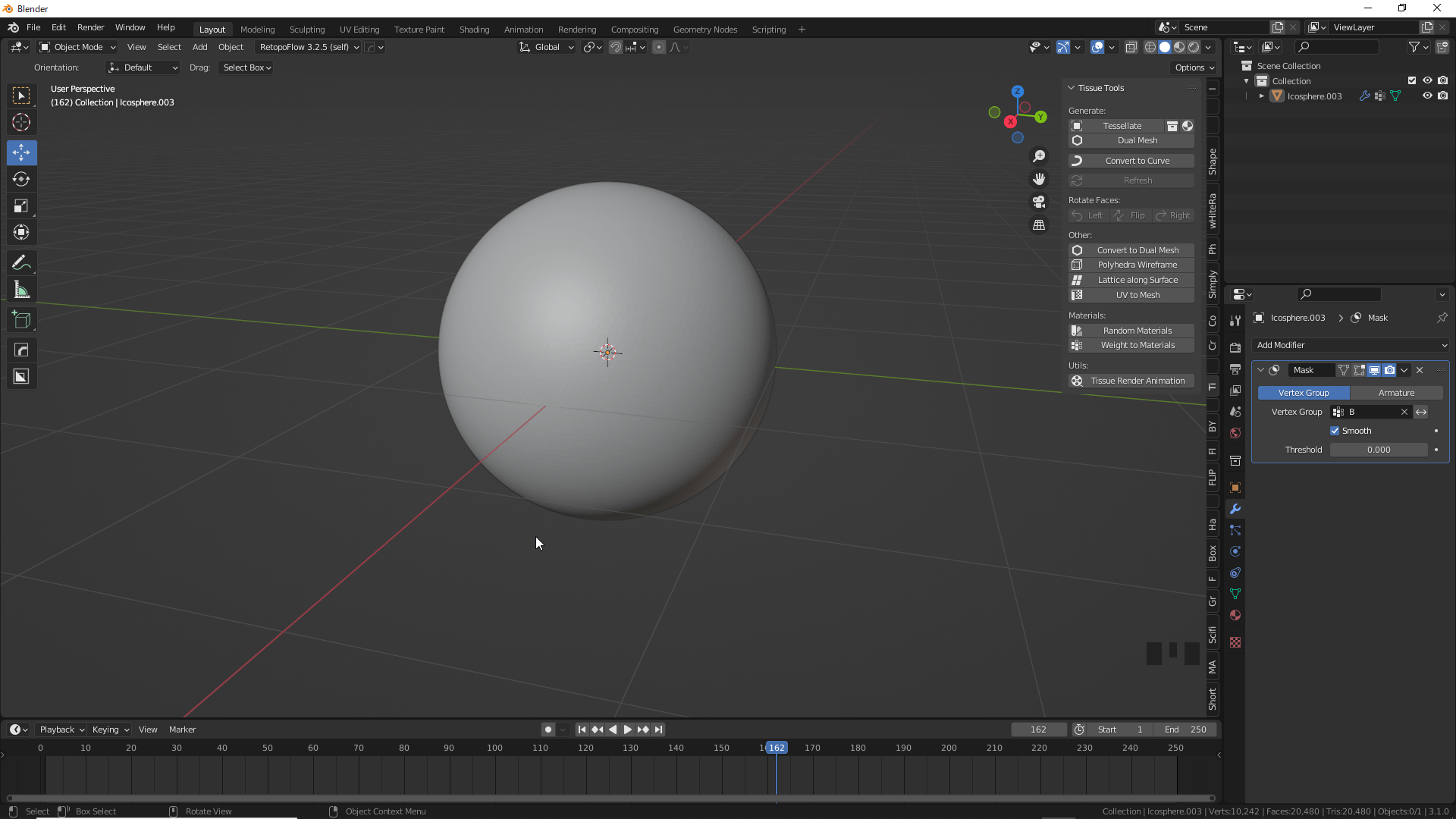
Mask modifier
You can change the area to be displayed by changing the value of Threshhold.
We recommend checking Smooth for a cleaner mesh.

Change the value of Threshhold
After that, add Smooth and Solidify modifiers to your liking and you are done.
Thanks for your hard work.
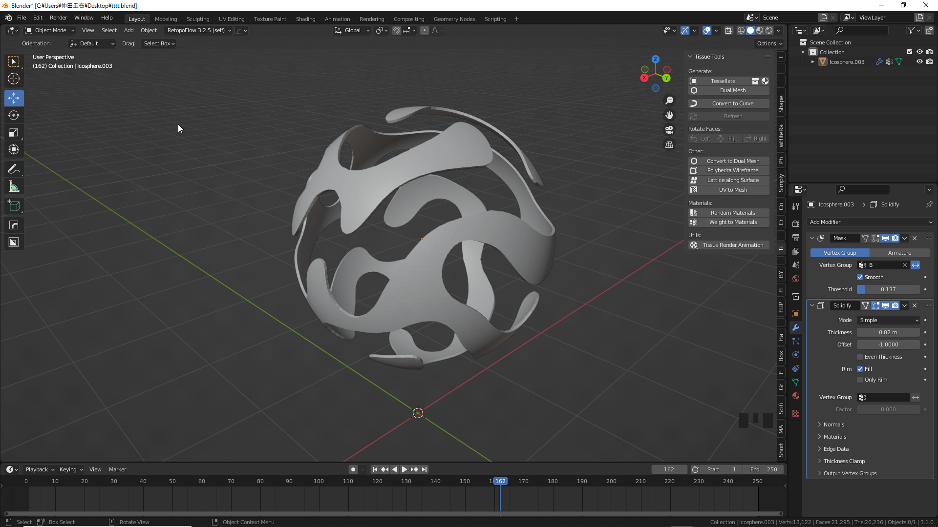
Add thickness with Solidify modifier for a cleaner look
How to upload to STYLY
Upload your 3D model to STYLY.
How to create a STYLY account

How to upload 3D models to STYLY

How to upload from Unity to STYLY
You can use STYLY FORUM to solve the problem. STYLY FORUM is a place where people can discuss a service or technical issue on STYLY, or provide bug reports on STYLY.
https://en.forum.styly.cc/support/discussions
This completes the upload to STYLY. Thank you for your time.
Placed on the scene STYLY!