In this article, we will show you how to create objects with Voronoi structure.
This shape, which looks somewhat like a living cell, can be used to create a variety of objects, from cheese to parts of futuristic buildings.
The version of Blender we are using: 2.92.0
What is Voronoi?
It is known by the name Voronoi diagram.
It consists of several randomly placed diagrams on a plane that are divided into regions according to the distance between the nearest points. If two or more points are close to each other, the figure becomes smaller, and if they are far apart, the figure becomes larger.
The boundary between the regions is the edge of the Voronoi diagram.

Voronoi diagram (taken from Wikipedia/Author:Mysid (SVG), Cyp (original))
In society, this diagram is used as a map to determine the location of school districts and new stores.
In nature, you can also find Voronoi diagrams in living things, such as the pattern of a giraffe or the wings of a dragonfly.
Create with Blender: Material Section
If you want to use it as a material, you need to create it with Voronoi Shader.
First, open Blender, select the cube, and click New in Material Properties.
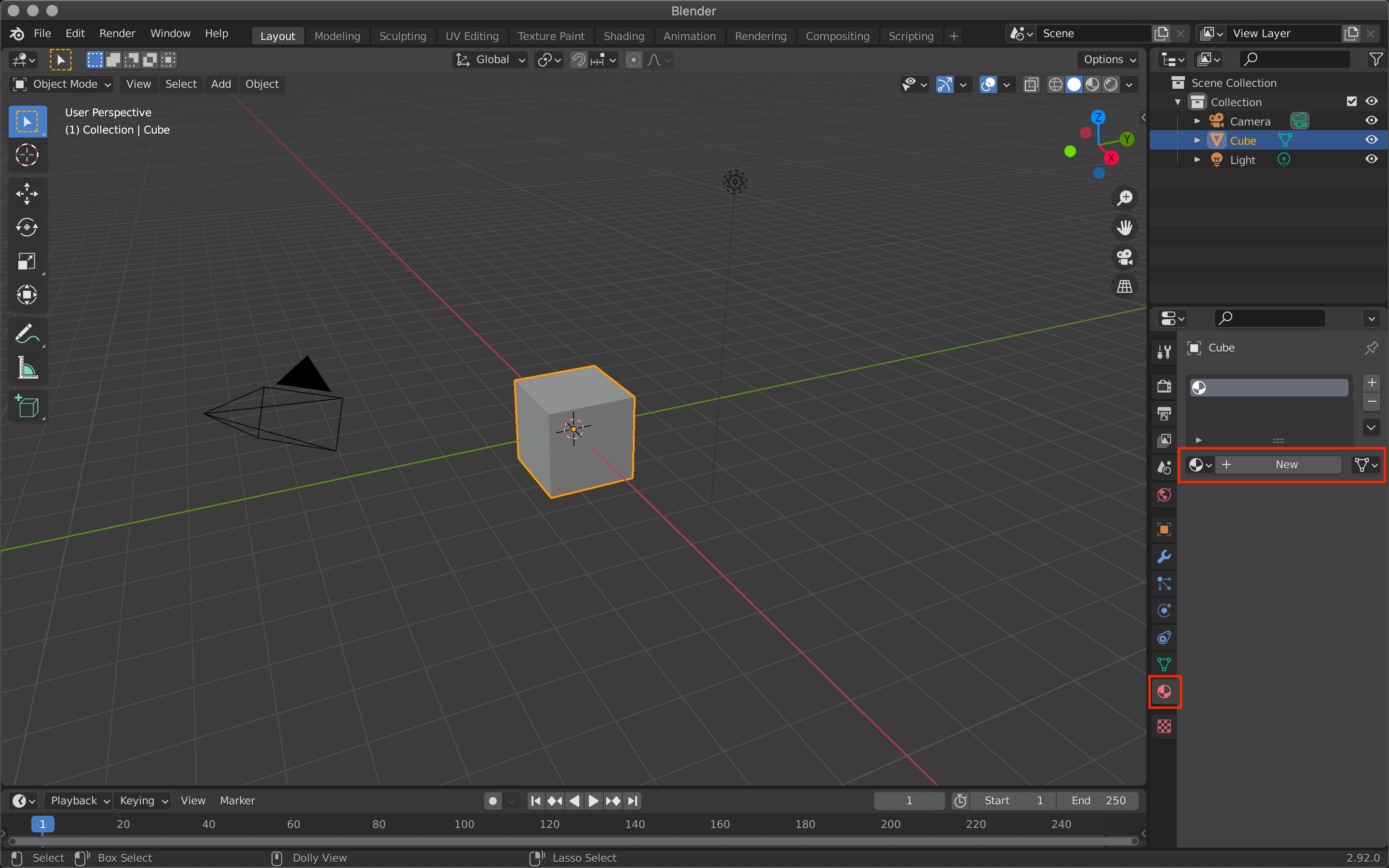
Material Properties.
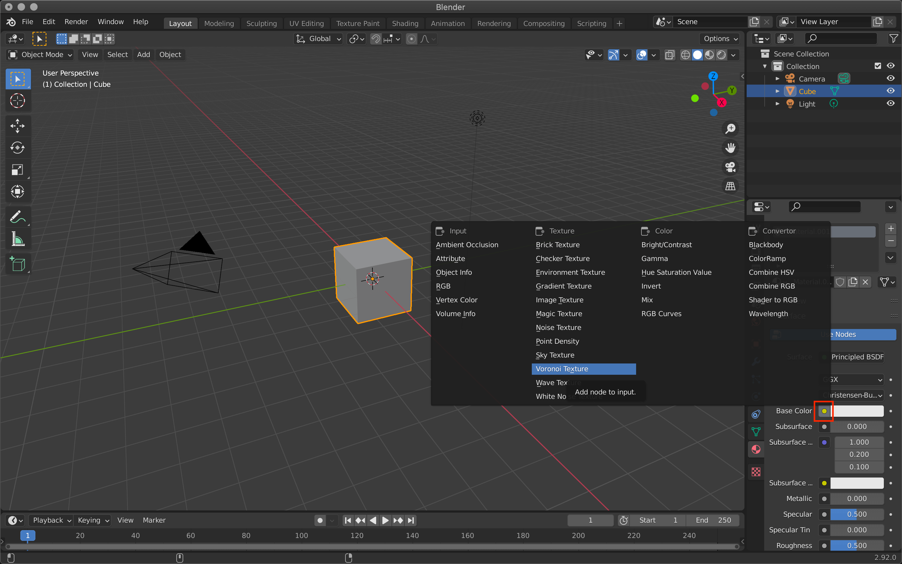
When the new material is created, select the yellow circle for Base Color -> Voronoi Texture.
Voronoi Texture.
If you select Shading from the top tab, you can see the preview and make detailed settings.
The colors have changed.
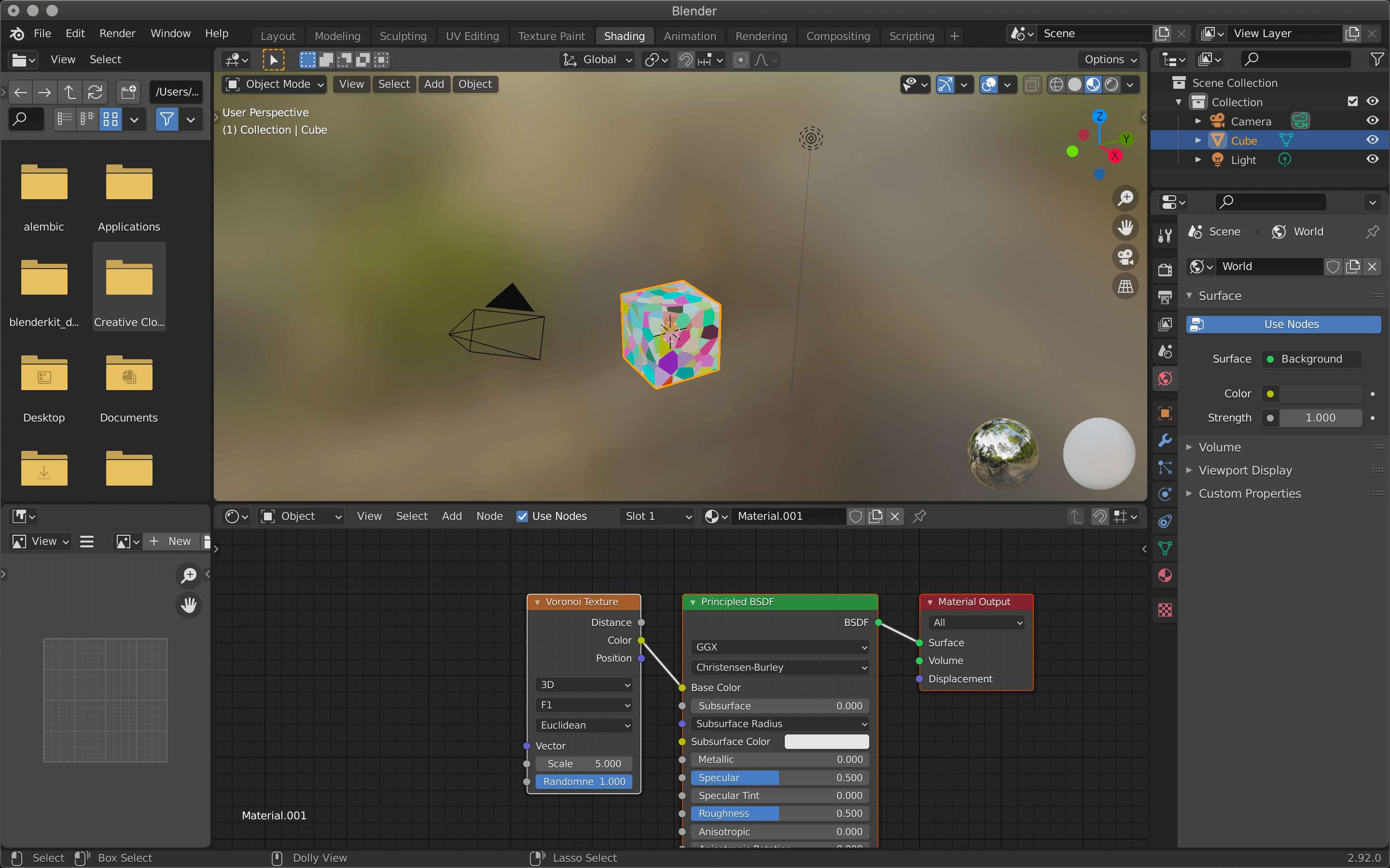
Go to the Voronoi Texture node in the Shader Editor at the bottom of the screen and make some detailed settings.
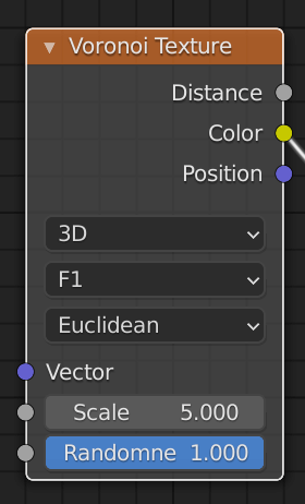
Voronoi Texture.
In the Shader Editor, you can combine various elements to create a single material.
Click on the circles on the rectangular items called nodes, and drag and drop them onto the circles of other nodes to connect them.
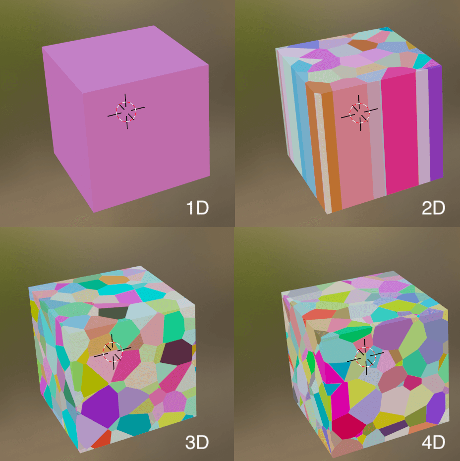
Dimensions
The dimension in which the shape will be reflected.
If you are using it for a three-dimensional object, 3D is basically fine.
Dimensions
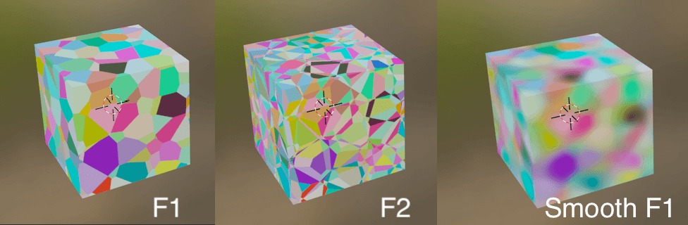
Feature Output
The type of shape determined by the node’s calculation.
Feature Output.
| F1 | Shape created by the distance between the closest points. |
| F2 | Shape created by the distance between the two closest points. |
| Smooth F1 | A blurred version of F1. |
When using Distance to Edge and N-Sphere Radius, the nodes will be cut off and the cube will turn black.
In this explanation, we have reconnected it to the Base Color, but by connecting it to a different node we can also express the surface in terms of irregularities instead of its apparent pattern.
The following paragraphs explain how to do this in detail.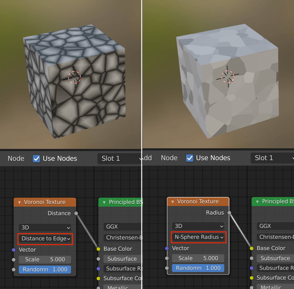
Distance to EdgeとN-Sphere Radius
| Distance to Edge | Distance to the corner of the Voronoi shape. |
| N-Sphere Radius | The radius of the N-dimensional sphere inscribed in the figure. |
Scale
The size of the shape.
Smaller values mean larger shapes.
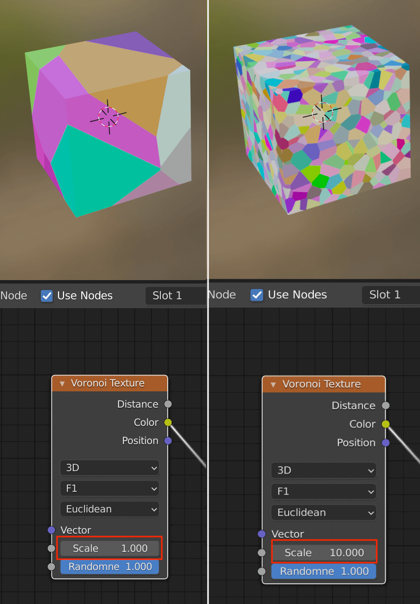
Scale.
Randomness
Determines the randomness of the shapes.
0 means a perfect grid, 1 means Voronoi.
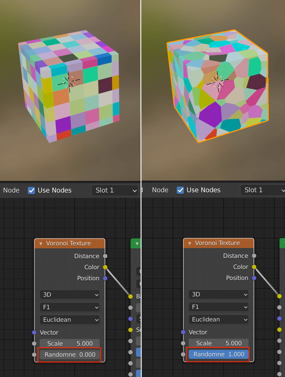
Randomness.
If you want to create an uneven surface with the Voronoi Texture, connect it to Displacement in the Material Output instead of Base Color in the Principled BSDF.
As the name implies, Base Color is the color setting for the surface, while Displacement is a technique that uses information from the texture to make the surface itself appear to be uneven.

Material Output.
This is already reflected at this point, but you can adjust the level of unevenness by inserting a node called Power between the two nodes.
Power is located in the math node called Math.
To do this, first press [A] in the Node Editor, and then type “Math” in the Search section of the menu that comes up.
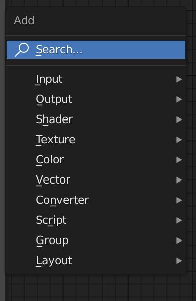
Add.
After selecting Math, move the cursor to the location where you want to insert the node and click on it to automatically connect the node.
After that, select Power from Add in Math.
You can adjust the amount of unevenness by changing the value of Exponent.

Select “Power” from Math tab.
Create using Blender: Object
If you want to make a Voronoi structure on the object itself, you can do it differently to a Voronoi Texture.
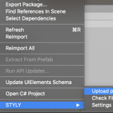
Activate the Cell Fracture add-on that is originally provided with Blender.
Select Preferences from the 3D viewport icon in the upper left corner and switch the screen.
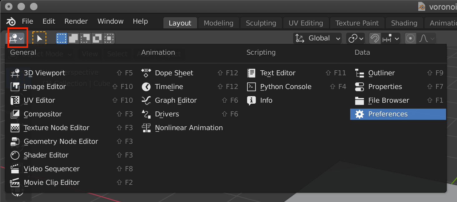
Preferences.
Type “Cell Fracture” in the search field in the upper right corner and check the add-on that comes up.
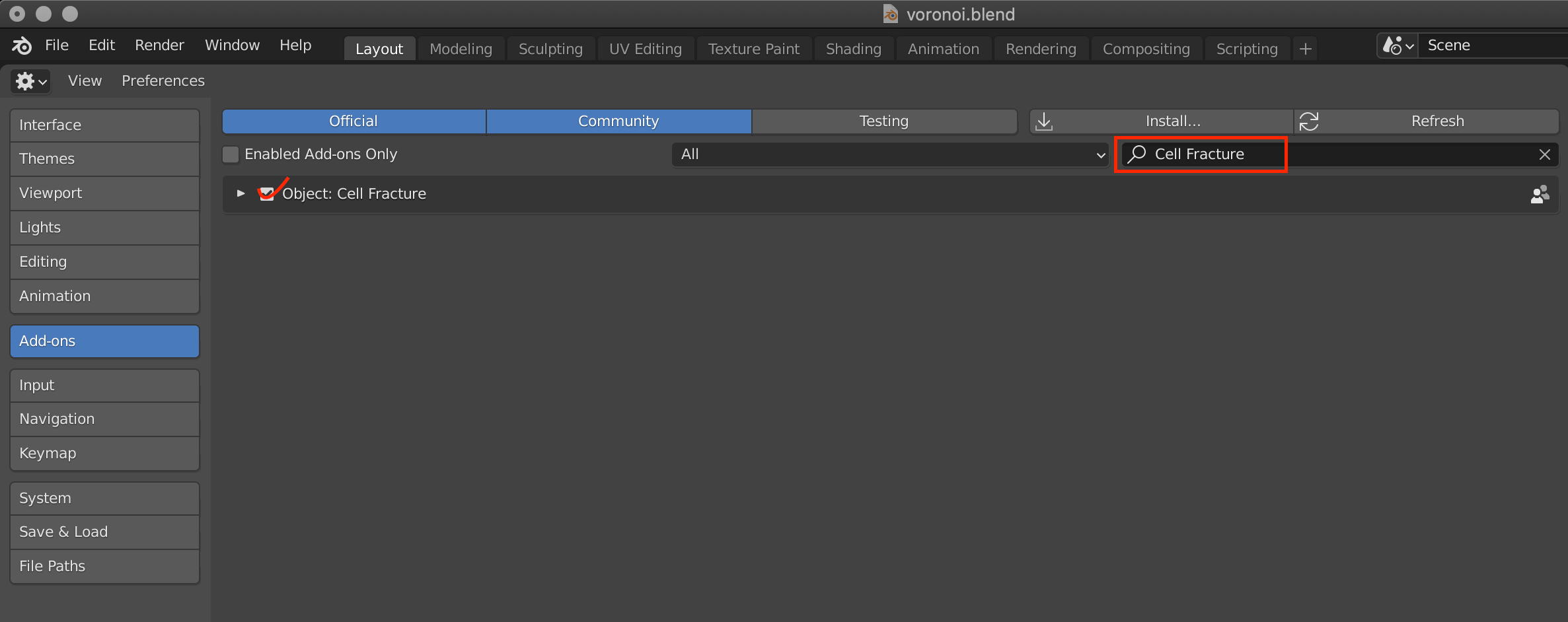
Cell Fracture.
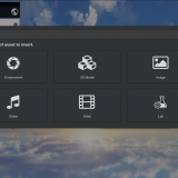
When you return to the 3D Viewport from the icon in the upper left corner, create a new object by pressing [Shift+A].
If you want to use the cube you used in the material section, change the material you set to something else.
![Click [X] to unassign the material.](https://styly.cc/wp-content/uploads/2021/03/Screenshot-239.png)
Click [X] to unassign the material.
With the cube selected, switch to edit mode by pressing the [tab] key or the upper left corner, and select all cubes by pressing the [A] key.
Then right-click on it and use Subdivide to subdivide it.
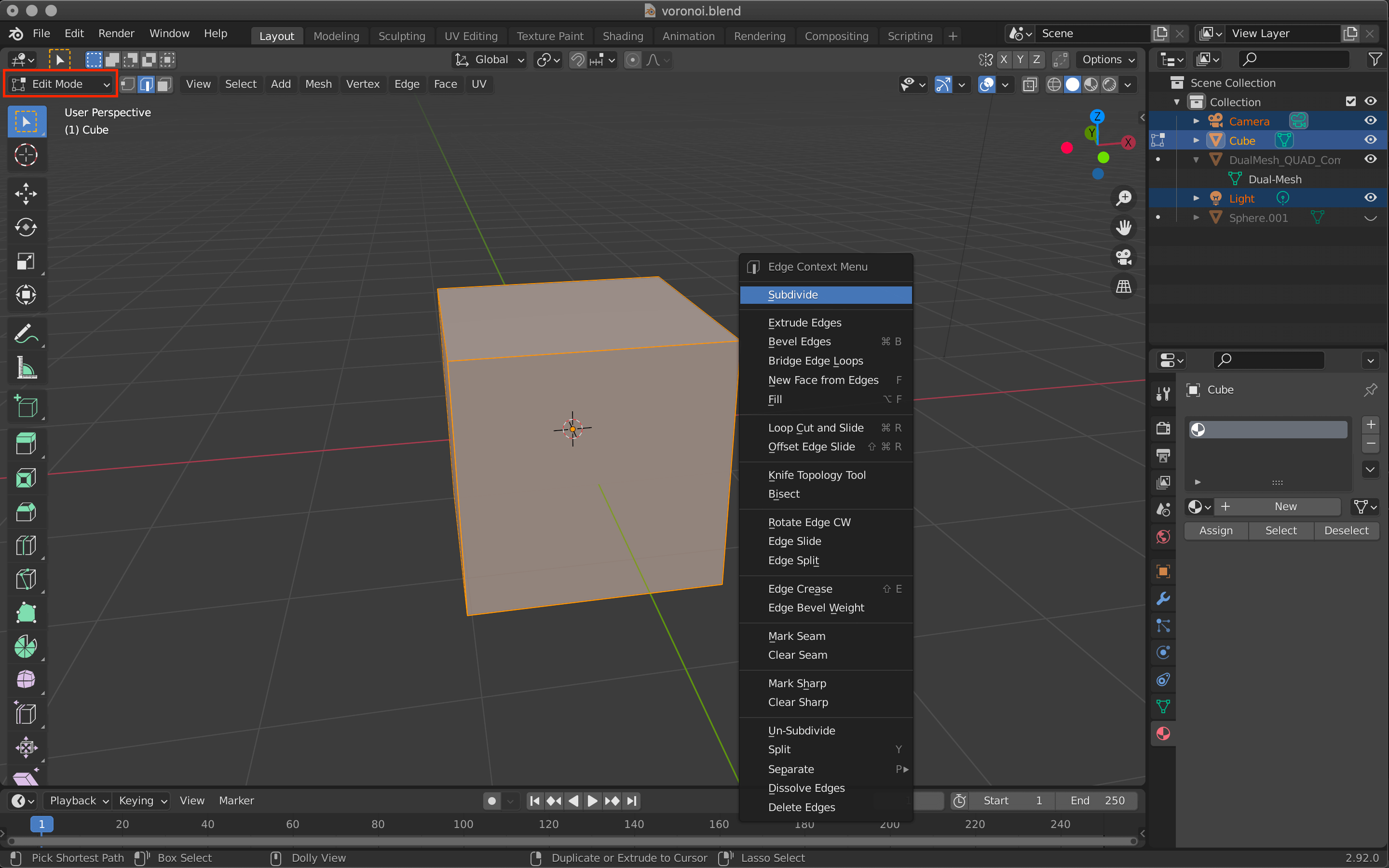
Subdivide.
Change the value of Number of Cuts from the bottom-left option to make it even smaller.
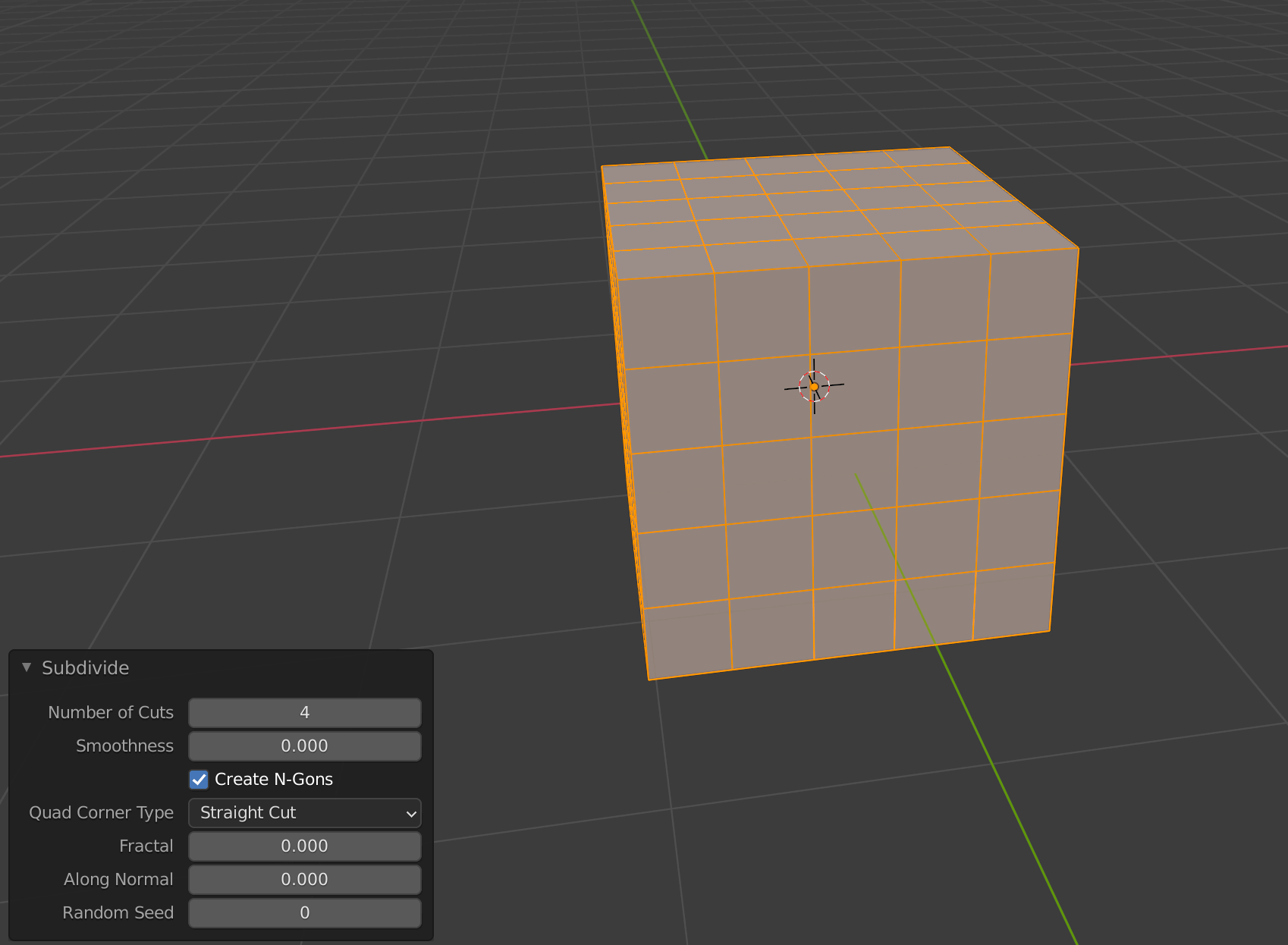
Number of Cuts.
Switch to Object mode again by pressing the [tab] key or the icon in the upper left corner, and select Object→Quick Effects→Cell Fracture.
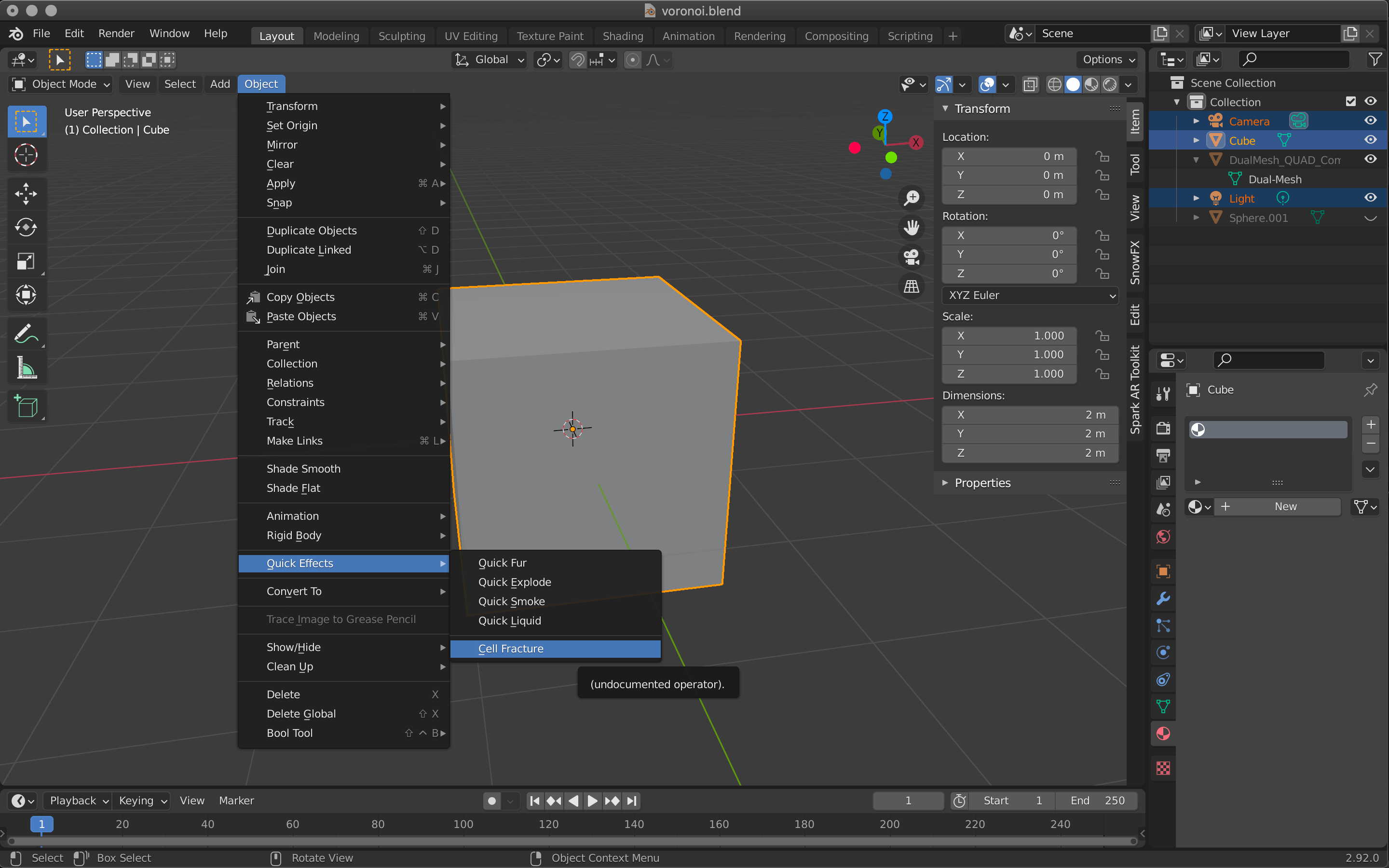
Cell Fracture.
When the menu appears, change the following items.

Cell Fracture.
Click OK, and the cube will break up into smaller and smaller pieces.
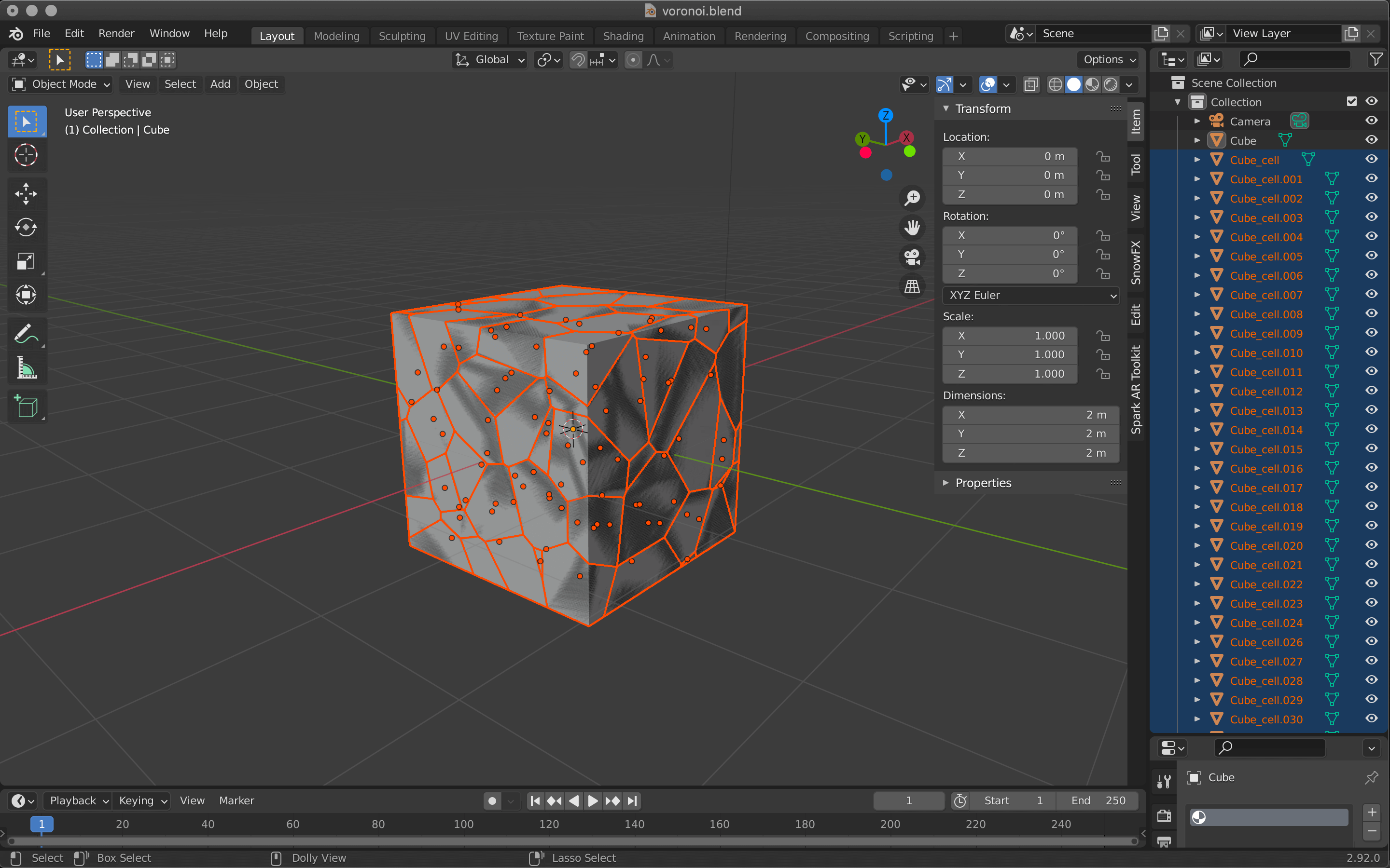
Cell Fracture.
When done, select the original cube only, and then delete it with X.
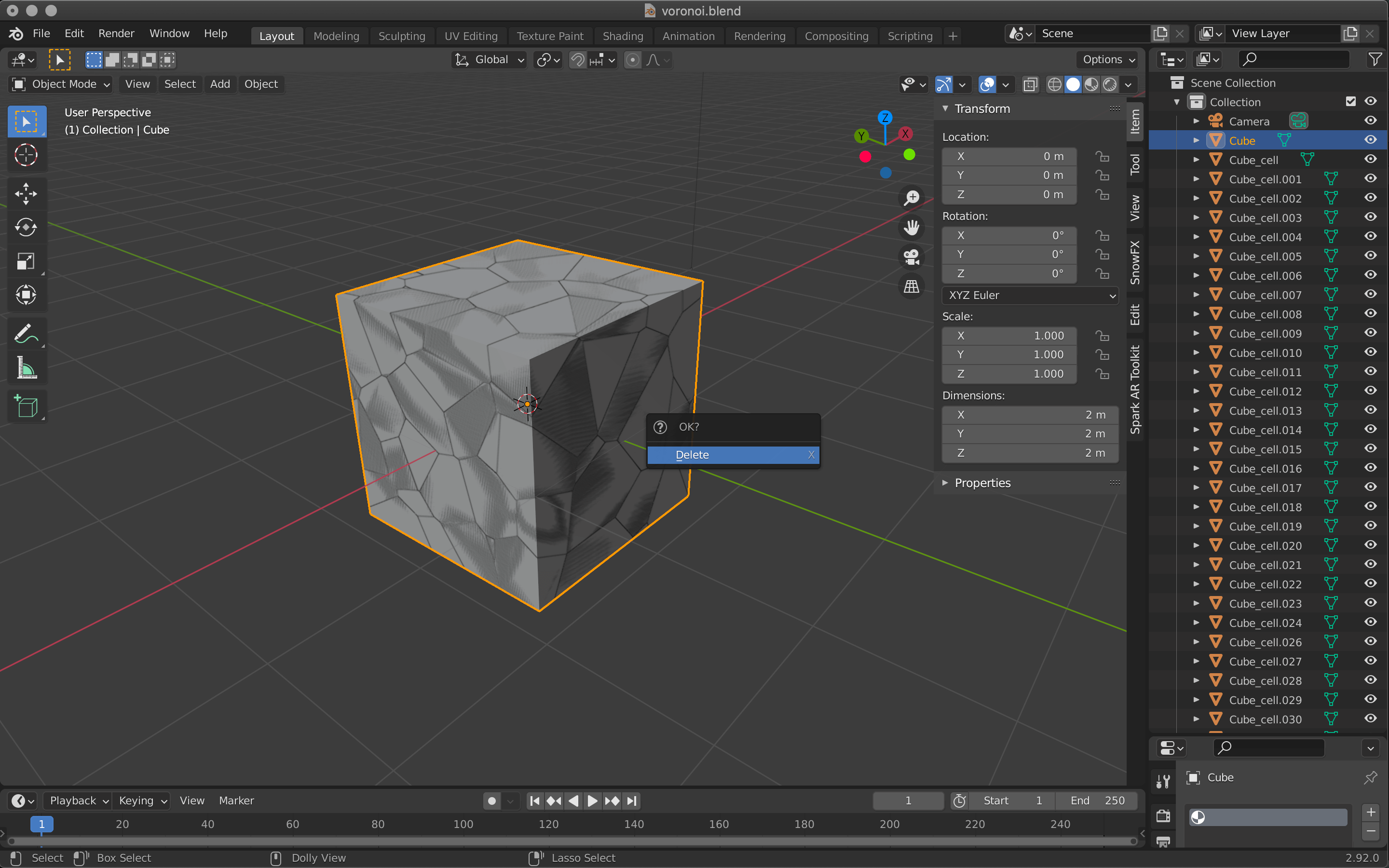
Delete with X.
Select all the split cubes and right click -> Join to merge them.
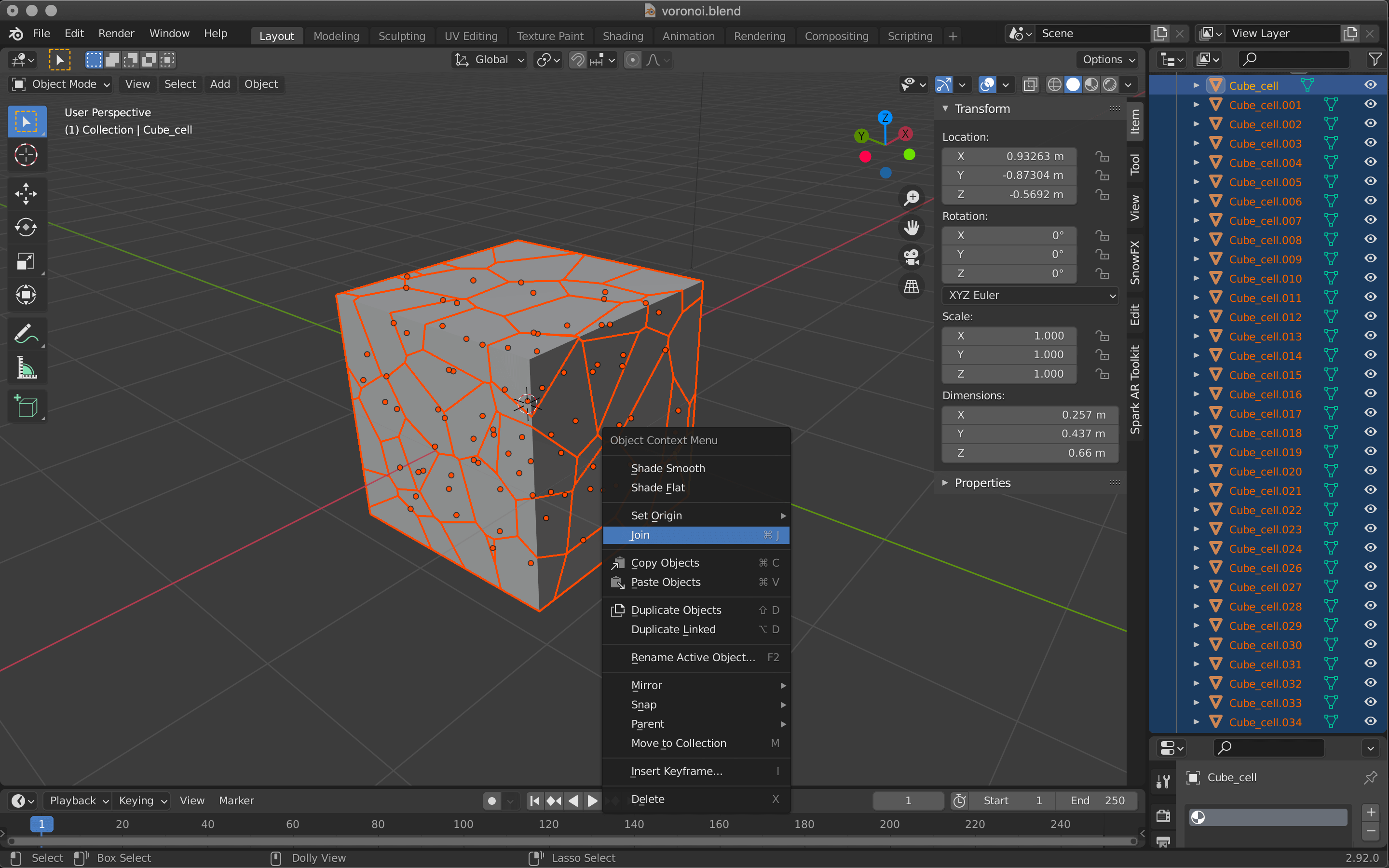
Right-click -> Join.
Now we have a single object, but the vertices of each piece are still overlapping each other.
We will delete these overlapping vertices.
In edit mode, select MESH→Clean Up→Merge by Distance.
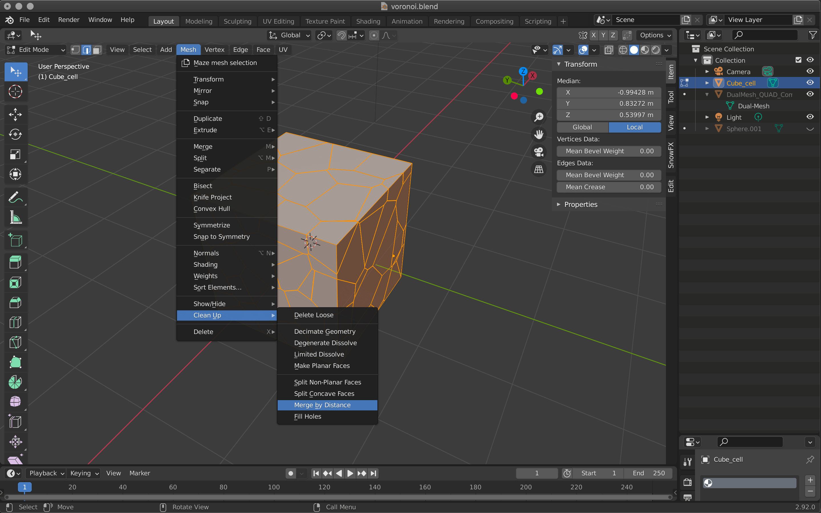
Merge by Distance.
Change the value in the lower left corner to 0.02m.
Vertices that are closer together than the value you set here will be merged.
Adjust the value accordingly so that the shape of the object itself does not change too much.
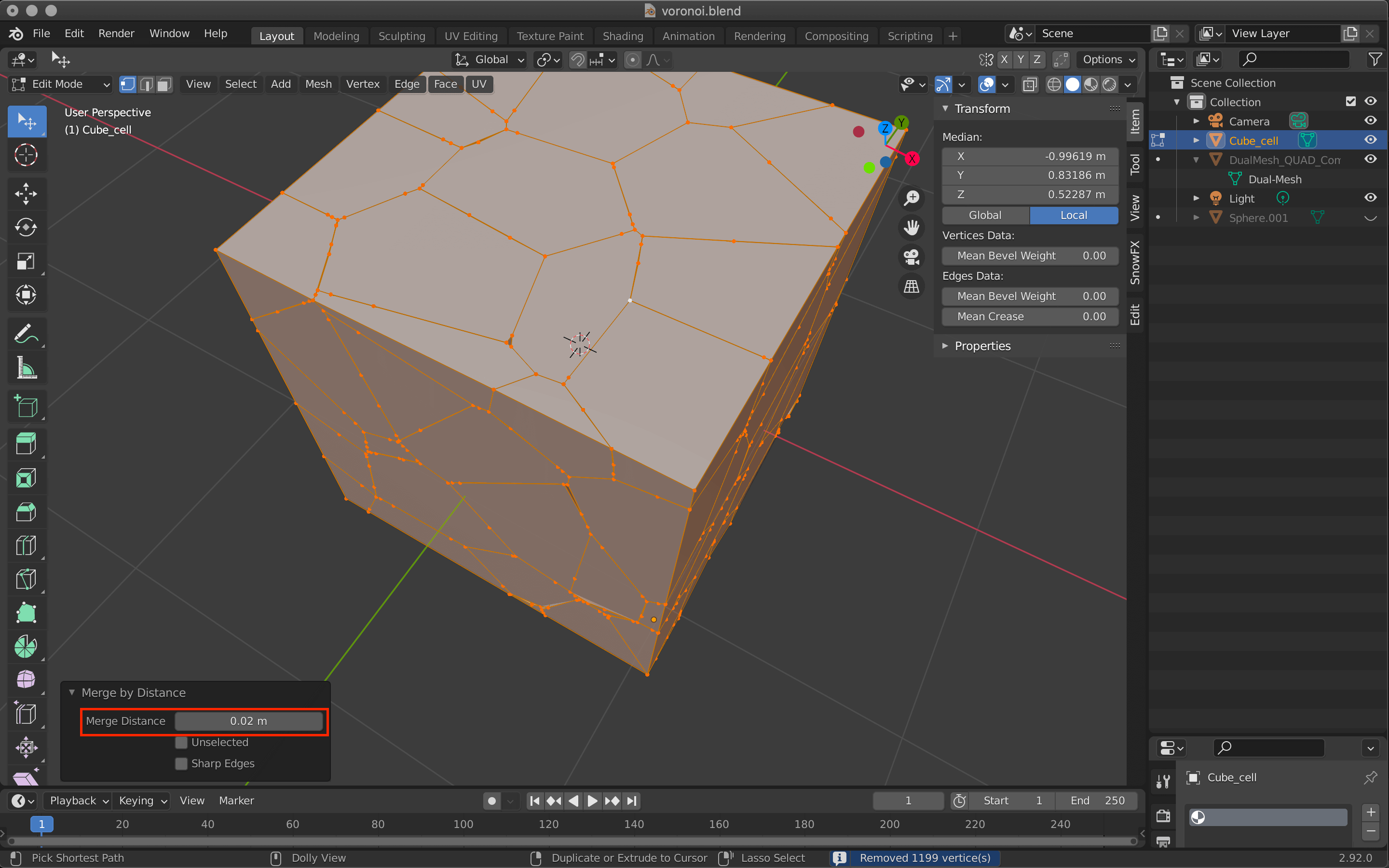
Merge by Distance.
When you are done, select Limited Dissolve from the same Mesh menu at the top.
This will reduce the number of extra vertices and edges.
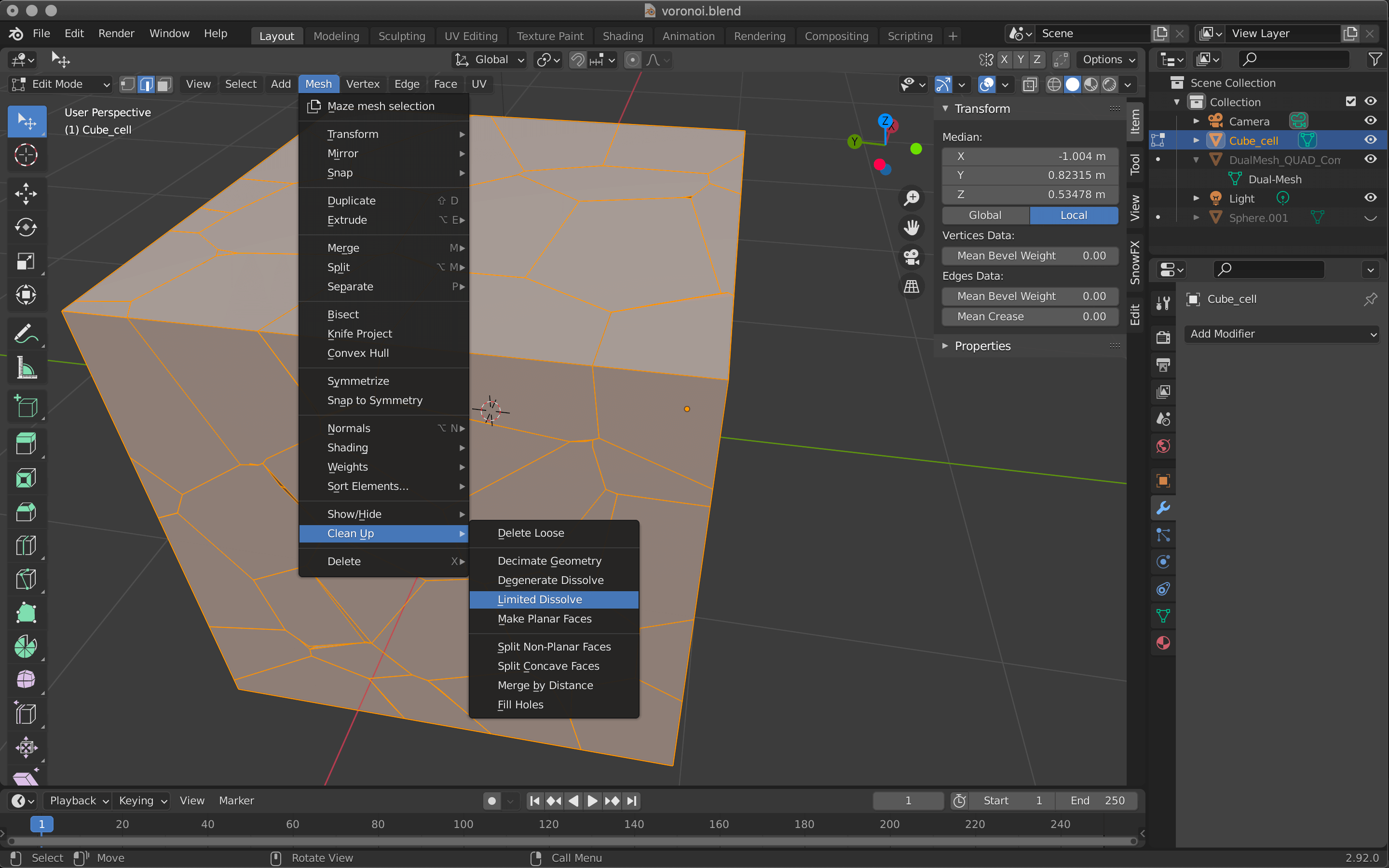
Limited Dissolve.
Select Add Modifier→Wireframe from the modifier properties on the right side of the screen.
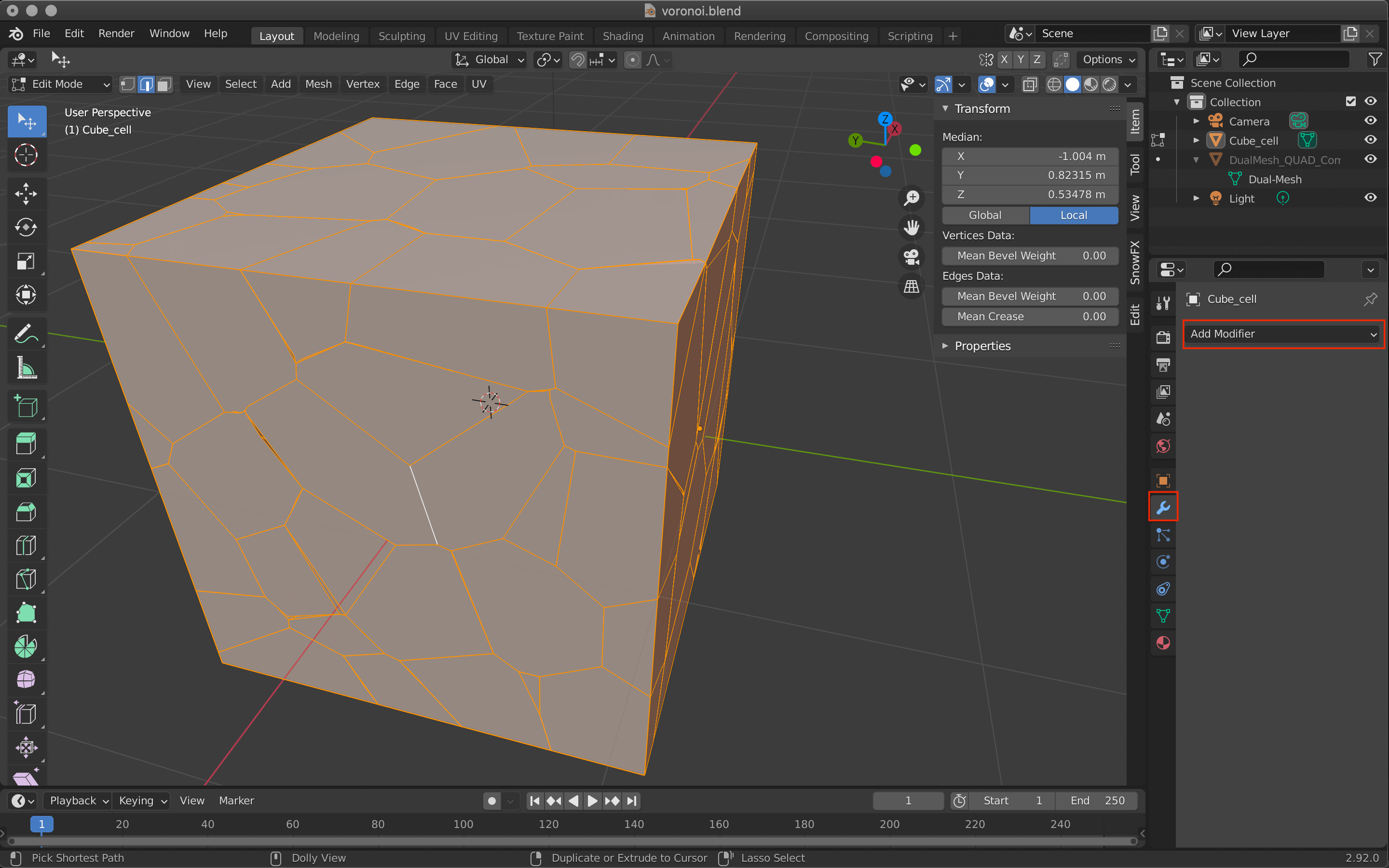
Add Modifier.
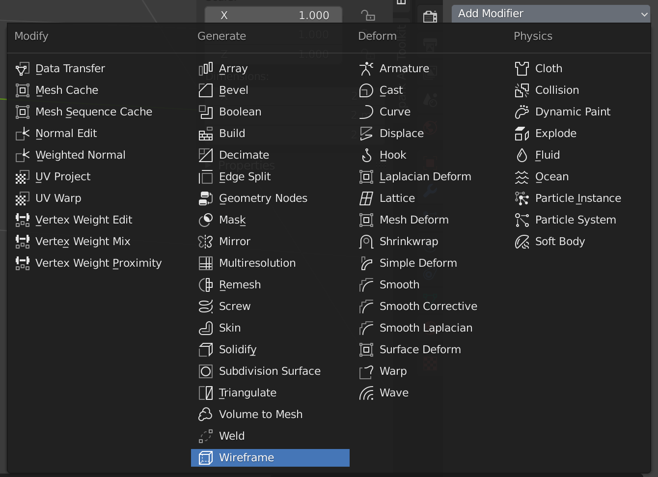
Wireframe.
Switch to object mode to see the preview.
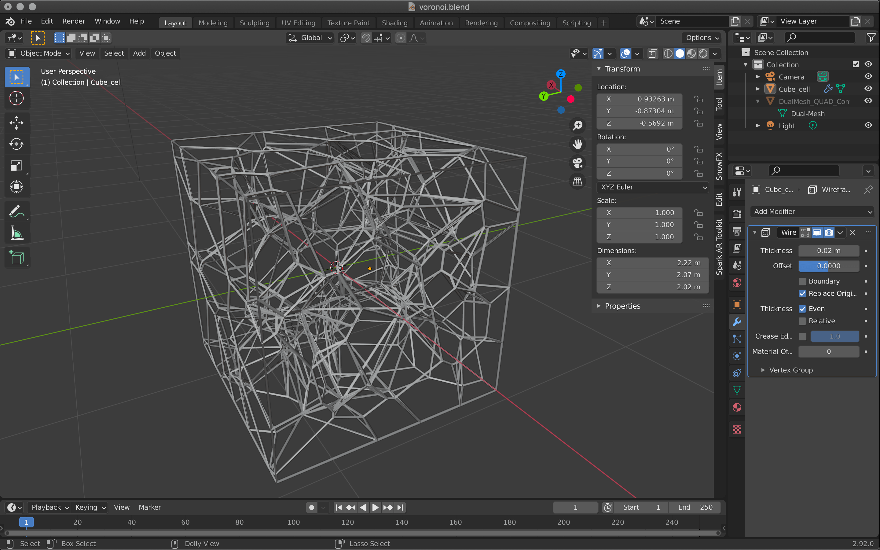
Wireframe.
To make it smooth, add Subdivision Surface from Add Modifire.
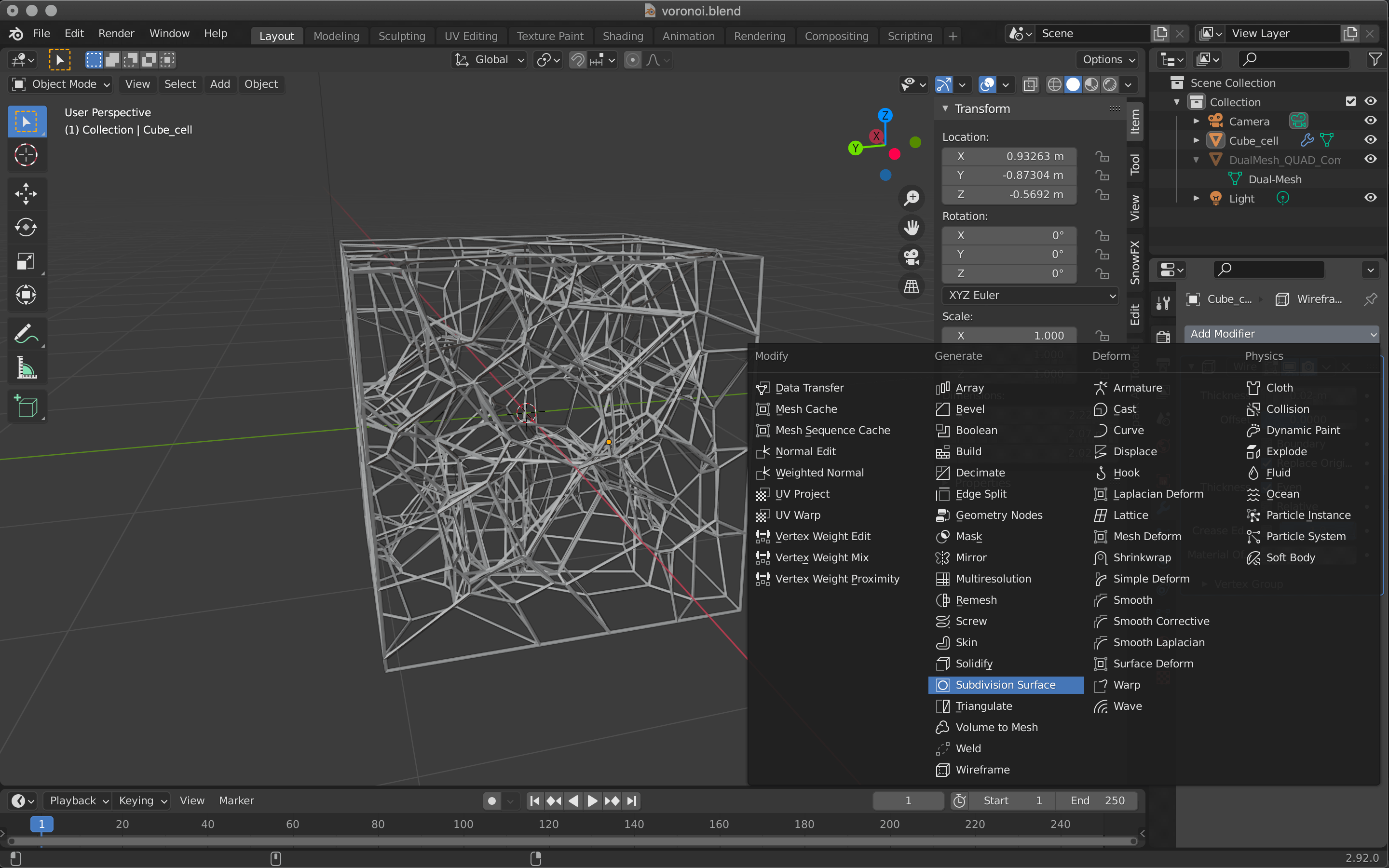
Subdivision Surface.
Increase the value of Levels to make it even smoother.
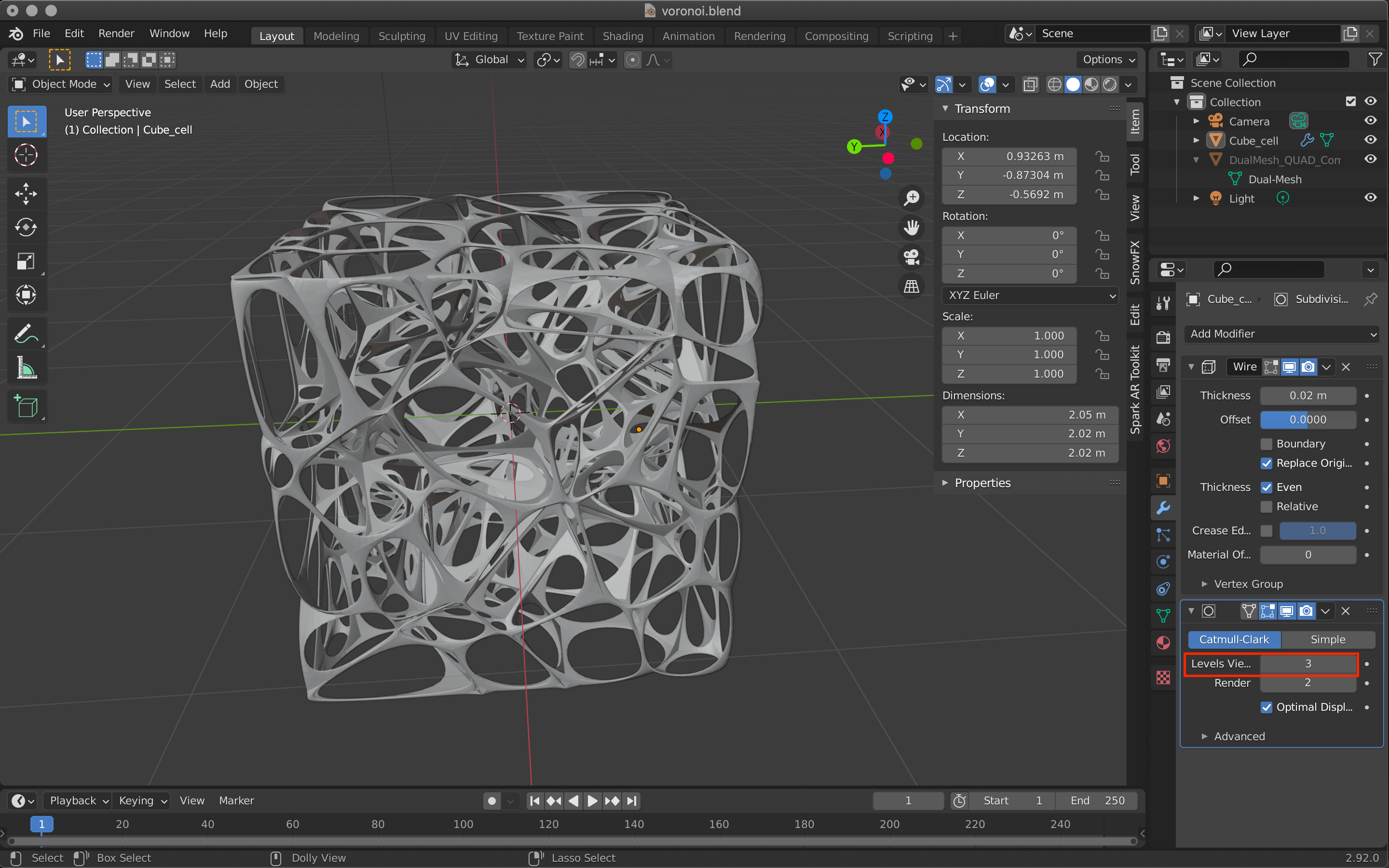
Subdivision Surface.
Click Apply on the Wireframe and Subdivision Surface to apply them.
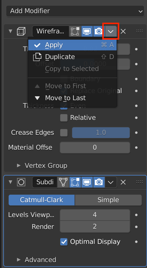
Apply.
The more polygons you add, the heavier the data tends to be.
It is a good idea to add Decimate from Add Modifire and reduce the number of polygons as much as possible before uploading to STYLY.
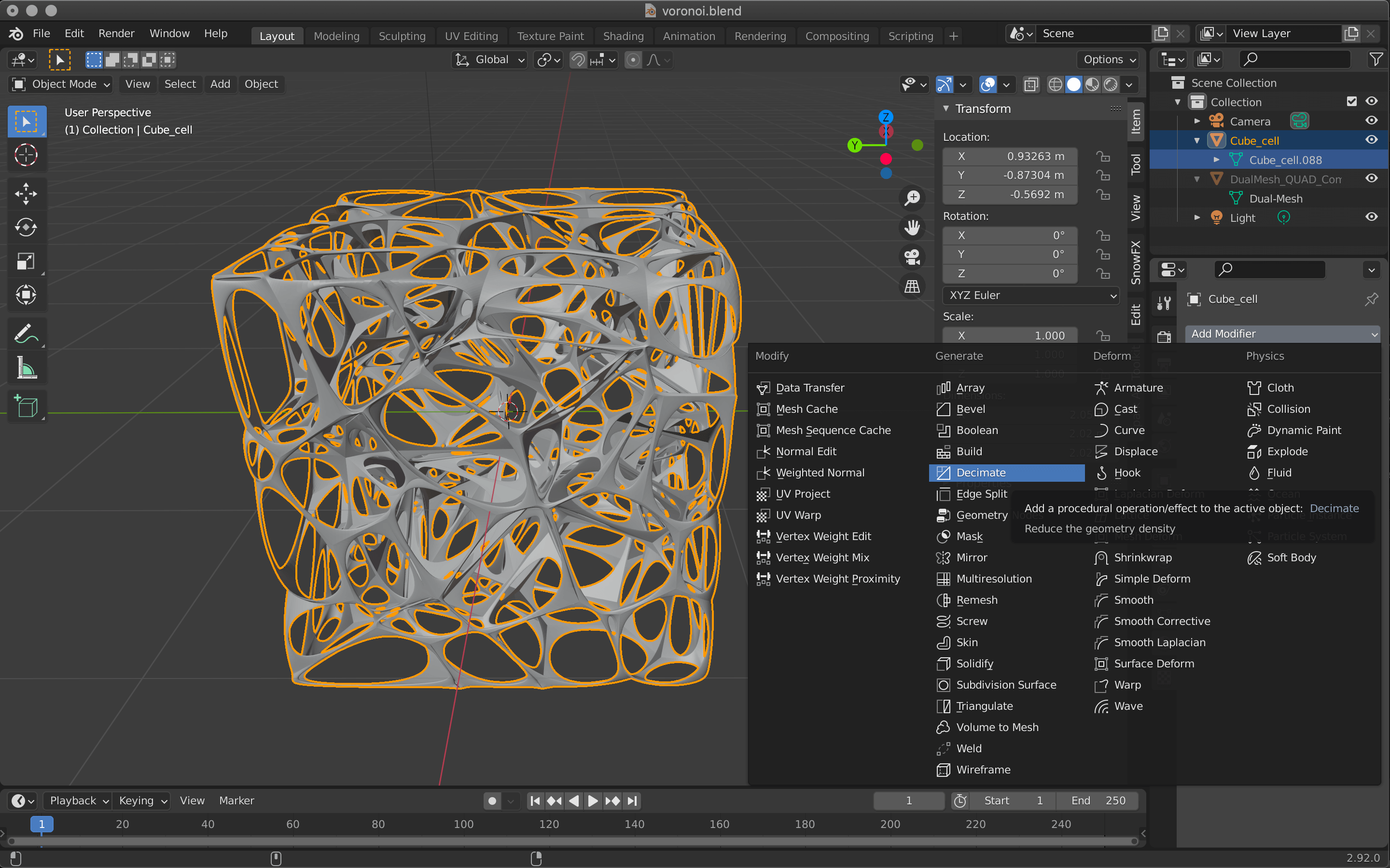
Decimate.
In Object mode, adjust the value of Decimate while watching the preview.
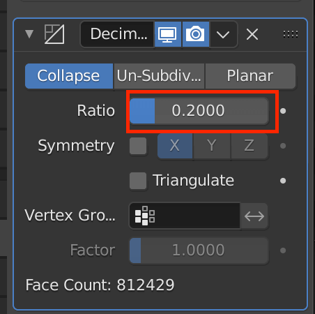
You can adjust how much Decimate is applied in Ratio.
How to upload to STYLY
Upload your 3D model to STYLY.
Create a STYLY account
How to create an account

How to upload to STYLY
How to upload from Unity to STYLY