Blender, like much three-dimensional computer graphics (3DCG) production software, offers a constraining feature. Using the constraining feature, you can save time when animating objects and adding dynamic motion. Thus, in this article, we show you how to use Blender’s constraint function.
What is Constraint?
Constraint is a function used to place a restriction on animated motion. The concept of constraint is not unique to Blender; in fact, almost all 3DCG software has a similar function. Due to its ability to constrain motion, this feature is primarily used for animation. However, even if you are not using the constraint function for animation, it can be useful to constrain the positioning of objects. In addition, the constraint function is used to restrict the movement of character models, such as joints, and is an indispensable tool for creating humanoid models.
By using constraint, you can create the scene featured in the image below; we will explain the production procedure later in this article.
Concept of Constraints
Object Relationships
In Blender, many constraints are set in relation to other objects. Thus, setting a “Target” puts specific constraints on an object, as well as how those constraints are viewed from a target object. In this article, these settings are referred to as the “constraint-set object” or “constraint side” and the “target-set object” or “target side.”
Constraints interact with the constraint-set object and the target-set object. For instance, if the target-set object is moved in a way that affects the constraint side, the constrained object will move in accordance with the constraint, but the target side will not move. However, if the target-set object is moved in a way that affects the constraint-set object, the constraint side will move according to the constraint. Ultimately, the constraint side will try to return to its initial position whenever possible.
Conversely, if movement is applied to the constraint side, the constrained object will not be allowed to move beyond the set constraint. For example, in the case of a “Floor” constraint, moving the target floor will cause the constraint side to move up like an elevator; lowering the floor will cause the constraint side to move down but not below its initial position.
If the constraint side is lowered toward the target object, it will hit the target side and not move any further because of the restriction.
In the next section, we explore “Types of Constraints,” including more information about floor constraints.
Base Points of Constraints
The base point of a constraint is determined by an object’s origin; therefore, if necessary, you can change the origin to set the base point. For example, if you want to create an elevator motion, set the base point at the feet of the human model.
For more information on setting the origin, please refer to the following article.
![[Blender] How to use origin and snap to model VR architecture](https://styly.cc/wp-content/uploads/2022/04/VR-building-howto-features-160x160.png)
Depending on the type of constraint, it is also possible to specify a “Vertex Group.” A vertex group allows you to designate which group to use as the decision.
If you want to create an elevator, for instance, you can use a vertex group to specify the elevator’s scaffolding. Note that the vertex group can only be specified for the target side.
Kinds of Constraints
Blender has many constraints that can be used in a wide variety of ways.
Floor
This constraint makes the target-set object look like a floor.
Floor Constraint Behavior
When the target floor moves, the object moves along with it. If you move the object toward the target, it will collide with the target and not move any further.
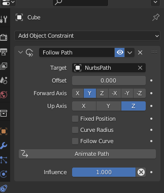
Follow Path
“Follow Path” is a constraint that follows the path specified as the target.
Follow Path
To use this constraint, specify the target and options, then press “Animate Path” to set the animation.
Limit Constraints
Limit constraints are used to set limits. “Limit Distance,” “Limit Location,” “Limit Rotation,” “Limit Scale,” and, although differently named, “Maintain Volume” are all constraints for limits. Of these, only Limit Distance specifies a target.
Limit Distance enables you to maintain the distance from one object to another. Thus, this constraint is a behavior that prevents objects from approaching within a specified distance. Additionally, for position, rotation, and scaling, a minimum and maximum value can be set for the X, Y, and Z axes, respectively. The constrained object will be limited to moving within its set specified distance and will not be able to deviate.
Copy Constraints
Copy constraints allow you to copy the state of an object to another object. Choose from “Copy Location,” “Copy Rotation,” and “Copy Scale,” as well as “Copy Transform,” which transfers all position, rotation, and scaling settings.
By using copy constraints, the state of the target is copied to the constraint side. For example, if you specify a rotational copy constraint, rotating an object on the target side will cause that rotation to be reflected on the constraint side.
Position, Rotation, and Scaling, when enabled, allow you to specify an axis, and Position and Rotation allow you to reverse the motion even further on an axis-by-axis basis.
位置コピーの設定
Clamp To
“Clamp To” is a constraint that restricts an object’s movement to a specific path. Clamp To is similar to Follow Path above, but it is not intended for animation; it merely constrains an object’s movement to one path. If Clamp To is set, any attempt to move an object will be locked and the object will not deviate from the path.
Clamp To
Damped Track, Locked Track, and Stretch To
“Damped Track” is the behavior of an object that is constrained to a minimum rotation and then pointed at another object with a specified target. Further, you can specify to have the object aim at a specific axis.
Damped Track
“Locked Track” is similar to the damped track described above but it can affect only a single axis.
Locked Track
“Stretch To” is a constraint that stretches an object.
Stretch To
“Track To” is another tracking method but it is an older type that tends to twist, so it does not work as well as the other methods.
Shrinkwrap
“Shrinkwrap” is a constraint that restricts movement to the surface of an object.
Shrinkwrap
Other Constraints
You can set up other constraints, such as parent-child relationships, IK, and armature when setting up character models, and motion tracking for tracking video and 3D models. However, these constraints are used for special cases and are beyond the scope of this article.
Flow of Constraint Setting
Constraint settings are the same for all types of constraints. Follow along with the steps below.
- Select an object.
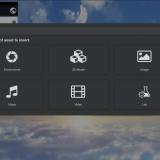
- From the Constraints tab, select “Add Object Constraint” and choose the constraints you wish to use.
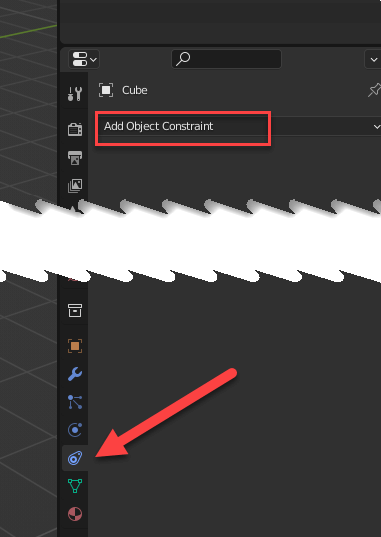
Add Object Constraint
- Specify options such as Target.
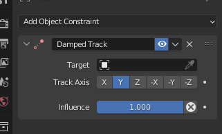
Constraint Option Settings
Multiple constrains, such as Damped Track and Copy Rotation, can be set at the same time.
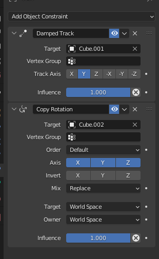
Multiple Constraints
With multiple constraints, the constraints are applied in order from the top.
Be aware: the order of the constraint can impact its behavior, so if the order is wrong the object may not be as you expected.
Influence Option
“Influence” allows you to specify how much influence each constraint has on an object.
You can use this option to reduce the influence of a constraint. For example, setting the Influence at 0.2 for the Copy Rotation constraint will cause the target to rotate only 1/5 of a degree after one rotation.
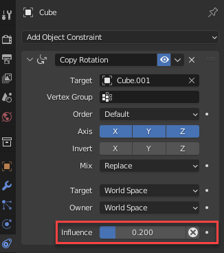
Influence Settings
Space
Some constraints allow you to specify the type of space, including “World Space,” “Custom Space,” and “Local Space.”
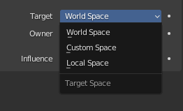
Space Settings
Space specifies the location of the coordinate system. If nothing is changed, World Space is the default setting, but you may want to specify a coordinate system that only affects the object itself, such as Local Space. The Space setting allows you to choose which location will receive the change. You can change the settings of the coordinate system from a dedicated menu. These settings are used, for example, when you do not want an object to be rotated from the World Space perspective, but you do want it to be rotated as an object.
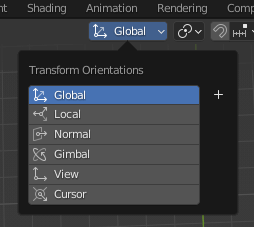
Specification of Spatial Coordinate System
Using Constraints
Now, let’s create a work of art using Constraints.
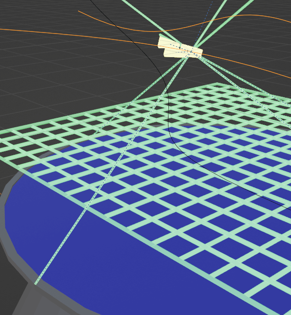
First, we will create a holographic work like the one shown below. This kind of hologram often appears in sci-fi movies when people are having a strategy meeting.
In this project, we will use three types of constraints:
- Follow Path
- Floor
- Damped Track
The pedestal, in our example, is made from a cylinder. Since this is for decoration, a simple base can be used for trial purposes.
In summary, we will be making the following parts:
- Pedestal
- Grids (One grid will show the ground and one will show the maximum altitude of the flying object; the latter is the grid that is up and down in the above example.)
- Flying object (group of three planes)
- Flying object (one plane with a different path than the three above)
- Laser beam (see below)
Creating Grids
We created this grid using the following modifier on a flat surface. Since this grid is also an expressive one, you can use anything you like.
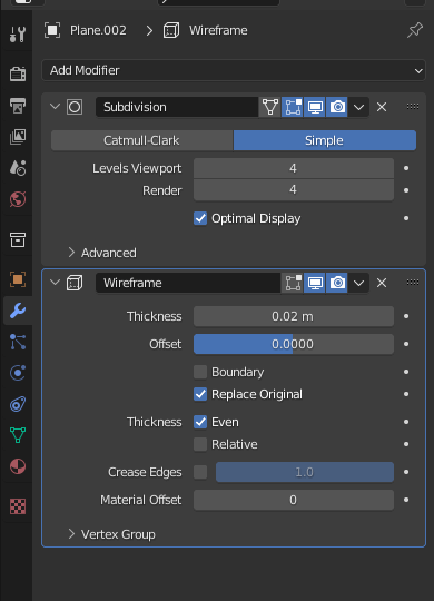
Grid Modifier Settings
Set up one grid near the pedestal with this as the ground and another grid just above it.
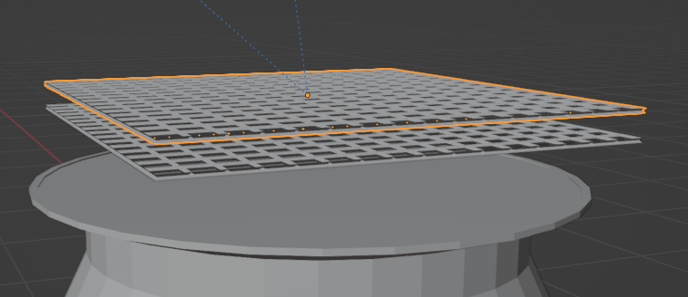
Grid Model
Create a Flying Object and Add Movement by Constraining
The flying object is simple, which we created from a cube.
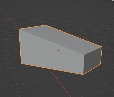
Flying Object Model
Next, create a flight path for the flying object.
The “Path” can be selected from the “Add” and “Curve” menus.
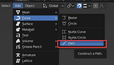
Path
Once the path is in edit mode, you can edit the curve by moving the line segment.
If you want to extend the curve, use the [E] key to push it out.
Edit Path
Now, let’s assign an object to this path.
First, click on the flying object. Then, in the constraint menu, click on Add Object Constraint → Add Follow Path constraint.
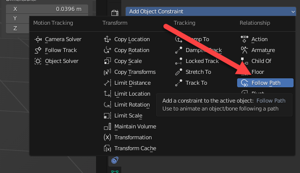
Constraint Menu
Select the path you just created as the Target. Then, click on Animate Path.
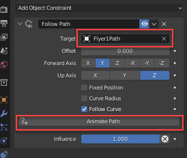
Select Path
The position of the flying object model you just created is probably floating in the air, so set this to (0,0,0).
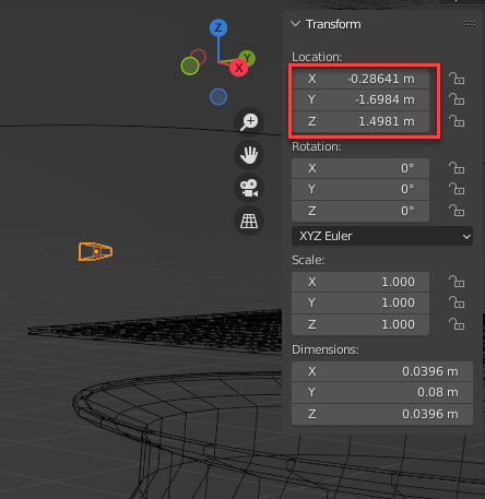
Object Location
It is important to make this change because, if this location is not set, the position of the object will be the difference from the base point of the constraint.
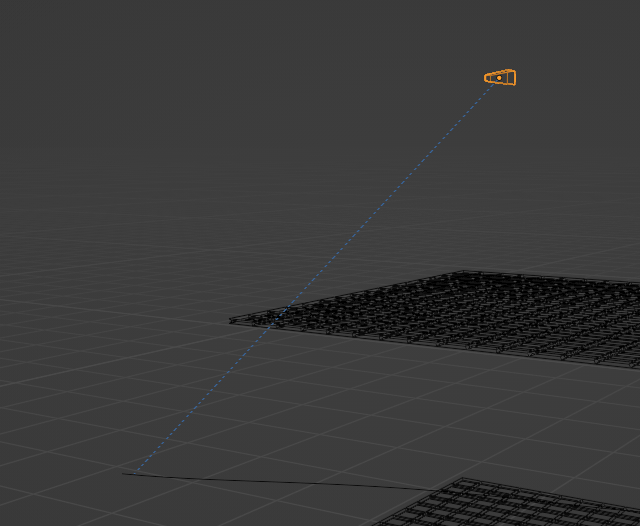
An Object Off the Base Point
Conversely, for example, if you want the object to float 2 meters above the base, set Z to 2 meters to float 2 meters from the base point with the constraint line.
If you set the location to (0,0,0), the result will be as follows:
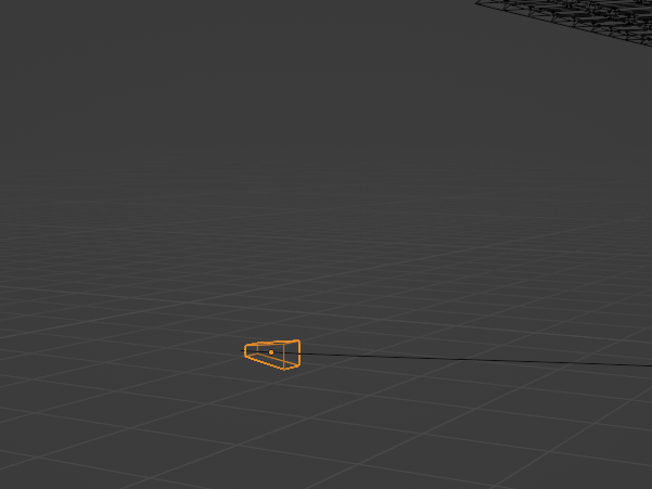
If the Position is Correct
In this state, the direction may be wrong as shown above.
To set the location correctly, try enabling “Follow Curve” and set “Forward Axis” to find a direction that works for you.
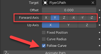
Axis Setting
Duplicating an object allows you to create another object with the same construction.
For example, by using [Shift]+[D] to move a duplicate object, you can easily create a regiment with the following formation:
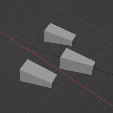
Flying Formation
Now, press [Space] to start playing the animation and check to see how it works.
Press [Esc] to stop.
If the animation is too fast or too slow, select a path, click on Path Animation, and change the frame values.
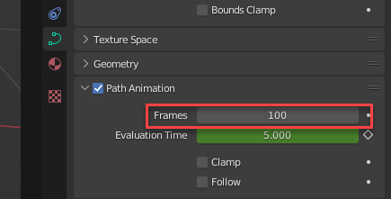
Frame Value
This number of frames means “advance the entire path over 100 frames,” so setting this value to 50 will double the speed.
In the example, we set up another flying object and assigned it to a different path, but feel free to place the duplicate object anywhere you like.
Let the Height of the Grid be the Height of the Highest-Flying Object
Now, let’s try to link the grid to the height of the flying object. We will try to match the top of the grid to the height of the highest-flying object. To do this, set the Floor constraint to the grid.
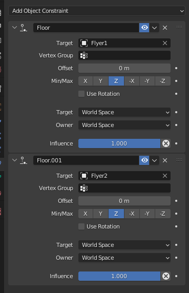
Setting a Grid Floor Constraint
Because the flying object is divided into two groups, we set two types of constraints. You can see that each separate object is set for a different target.
Since we want to control the vertical movement, the Z axis is set as “Min/Max.”
You can see the animation by pressing [Space] after setting this vertical movement.
Laser Beam Settings
Next, we will add a guide beam that looks like a laser beam for searching.
This beam is made of a thin, stretched-out cylinder.
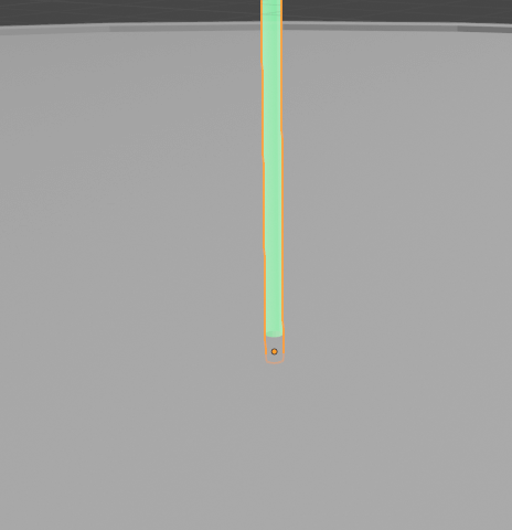
Laser Beam
Next, let’s add a Damped Track to this. Set the flying object as the target.
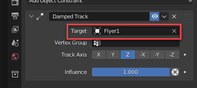
Target Flying Objects
At this time, you may have taken the following wrong turn:
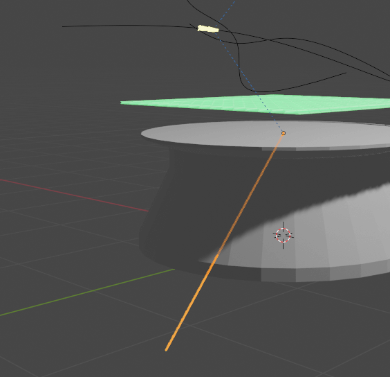
Misdirected Objects
If you find that your objects are misdirected like the image above, try changing the “Track Axis.”
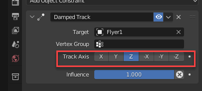
Track Axis
The beam will then track correctly. You can make multiple beams track by duplicating and moving them with [Shift]+[D].
Multiple Beams Tracking
Use Your Project in STYLY
To use your finished product in STYLY, some preparations are required. Since we will be using Unity, please prepare Unity with the STYLY plugin installed.
Export in FBX
When you export your work, you will need to include animation in the output. When you are doing this step, make sure that “Bake Animation” is enabled and “NLA Strips” and “All Actions” are disabled.
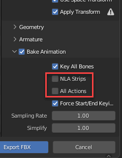
Animation Settings to Remove in FBX Output
Your animation will be imported into Unity and included in the imported prefab.
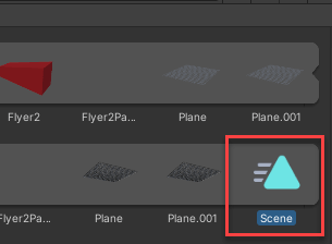
Animation in Prefab
Select this animation, press [Ctrl]+[D] to duplicate it, and then select the duplicated animation.
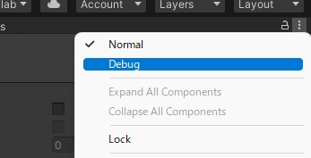
Debug
Next, press the menu button on the sidebar (the button with the three vertical dots) and select “Debug” from the menu that appears.
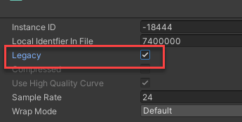
Legacy Setting
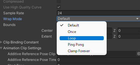
Then, check the “Legacy” box. From here, go back to “Normal” from the menu button. Then, you will see the screen in the image below, so set “Wrap Mode” to “Loop.”
If you do make this selection, the animation will not loop and will stop after one playback. (Of course, if this is the appropriate behavior for your work, this setting does not matter.)
Wrap Mode Setting
Next, after placing the prefab in the scene, add an “Animation” component to the prefab and add the previous animation to the “Animation” item.
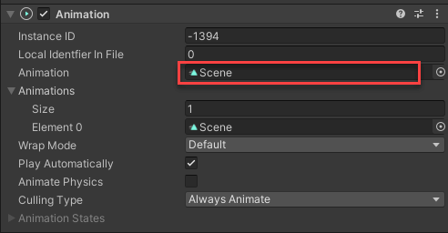
Animation Component Setting
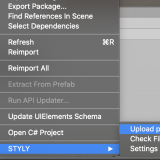
By prefabricating this object and uploading it, the object will play in STYLY. We have enhanced our sample output with post-processing and material settings, such as luminous objects, to enhance the sci-fi feel.
![[Introduction to Unity] How to create and use materials](https://styly.cc/wp-content/uploads/2020/09/catch-160x160.png)
![[Unity]Understanding the Basics of Post Processing](https://styly.cc/wp-content/uploads/2020/07/EYECATCH-1-160x160.png)
Supplement: Animation Contents
Unity and STYLY do not analyze the contents of the constraint and play the animation, but Blender outputs the animation with all objects’ animations baked in.
This means, for example, that if you change the position of a flying object in Unity, the other objects will not be linked.
To change this setting, you will need to adjust it in Blender and export it again.
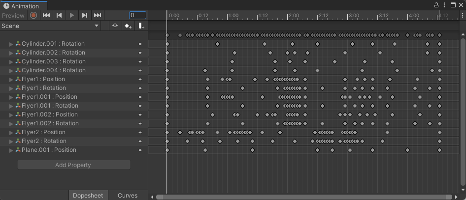
Animation Contents
STYLYにアップロードする方法
How to Upload to STYLY
How to create an account:

How to upload to STYLY:
How to upload from Unity to STYLY:
If you have any questions about STYLY, bug reports, or requests for improvements, please contact the STYLY FORUM.
https://en.forum.styly.cc/support/discussions
Using constraints, as we have in our example, makes it possible to incorporate predefined movements, even when the number of objects increases. This method allows you to create a multitude of diverse artworks, so try combining various types of constraints in your pursuit of interesting movements.