By making full use of drawn curves, smooth lines can be expressed and, when used in conjunction with various illustration creation software such as Blender, hand-drawn pictures can be incorporated to create three-dimensional (3D) assets. In this article, we explain the basics of using curves in 3D graphics, tracing with Inkscape, the open-source drawing application, and more!
What are Curves?
In a nutshell, curves in 3D graphics are continuous lines that are expressed based on mathematical equations. Of course, all geometry displayed on the screen in 3D graphics is based on mathematical calculations, but “continuous” is an important attribute of curves. For example, a cube on the screen is divided by vertices. A curve, however, is treated as a line drawn and expressed as a mathematical formula, having the advantage of infinite resolution.
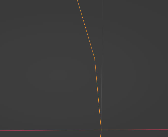
Enlarged Mesh
Take a look at the image of a mesh above. Even though it appears to be a perfect circle from a distance, as you look closer, you notice that it is composed of edges.
How about a sphere represented by curves?
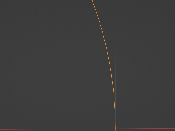
Enlarged Curve
You can see that the corners, as a surface, do not stand out.
If you want to display something smooth with a mesh, it will need to be subdivided into more surfaces. For something that is represented by a curve, however, this subdivision is not necessary.
Using curves offers the following advantages:
- Curves can represent smooth lines efficiently, continuously, and with high accuracy. With meshes, the number of faces are finite and must be large for high accuracy, and the load can be very high.
- The accuracy of the deliverables can be set at output. This means that you can use a higher precision while working (to reduce file size, etc.) and then convert to a rougher precision before outputting.
Some of the drawbacks of using curves include:
- Merging multiple shapes, while relatively easy to accomplish with meshes, is rather difficult with curves.
- Many operations supported by Blender are not supported in the curve state, so mesh transformations may be required to perform certain tasks.
Types of Curves Available in Blender
Below, we explore the types of curves available in Blender. We used Bézier curves for this project, but we also explain other formats for reference.
Types of Curves
Bézier Curve
As a concept, the Bézier curve has a long history, existing since the early 1900s, and is supported by many other computer graphics software programs besides Blender.
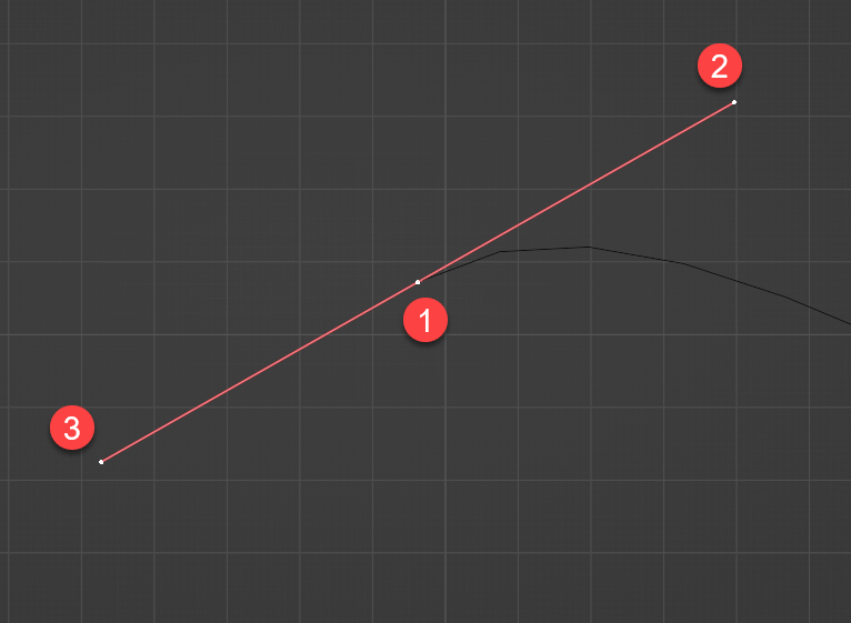
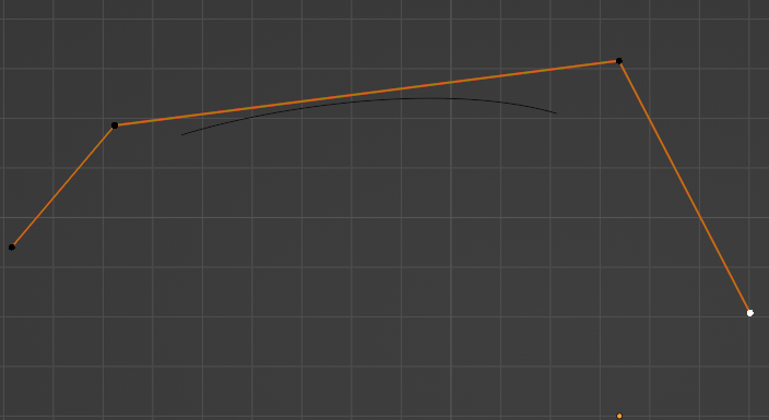
Bézier Curve Control Points
For the Bézier curve control point feature, there are two “handles” (2 and 3 above) for each “control point” (1 above). Thus, the position of the line segment can be specified at the control point and the curve can be adjusted by moving the handles.
Example of Bezier Curve Control Points and Moving Handles
NURBS
NURBS (Non-Uniform Rational B-Spline) are another curve supported by Blender, which have different characteristics than the Bezier curve.
Control Points of the NURBS Curve
Unlike Bézier curves, NURBS are shaped in such a way that the position and weighting information of each control point determines the overall shape of the line segment. In addition to control points, NURBS have “knot” points, which are the actual points that the curve touches (explained in the next section).
Example of Moving the Control Points of a NURBS Curve
Path
“Path” is a special form of NURBS curve with knots at both ends.
Unlike regular NURBS, both ends of Path are fixed, making this type of curve suitable for indicating the movement of an object, as well as for representing shapes.
Path Example
Other Curve Variants
Font
Although Blender allows you to enter text, text is also special curve data. Font enables editing as a string of text, and text can be converted from the Font state to a curve.
Connected Curves
A connected curve, such as a Circle, is connected to both a start and end point.
Basic Operations
Blender’s curves have a wide variety of functions and can be used to generate complex 3D shapes. However, in this article, we focus on creating 2D illustrations, etc., and converting them into 3D graphics, so we explain just the basic operations of Blender and how to use Bézier curves.
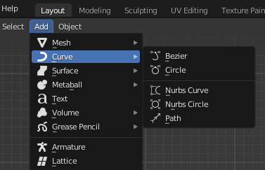
Adding Curves
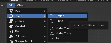
To add a curve, select Add > Curve > Bezier.
Adding Curves
Curve Editing
Press the [Tab] key to enter the curve editing mode, where control points and handles are displayed.
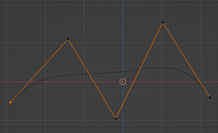
In curve editing mode, moving the control point changes the position of the line segment, and moving the handle changes the angle of the line.
Bézier Curve Editing
Mastering curve editing takes some getting used to, but basically, once you learn how to move a handle to change the curve, you will be able to move it freely. First, select a handle and press the [V] key to bring up the “Set Handle Type” menu. There are several types of handles to choose from; for example, selecting “Vector” will make the handle a straight line.
Setting Handle Type
Setting Curve Object Properties
Selecting a curve object allows you to choose dedicated object properties.
Curve Object Properties
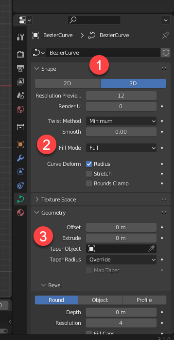
The curve object tool contains many options, but the one we are using is largely the one shown in the numbered steps above and described below:
- Button (1) is in the “Shape” settings and allows you to choose whether the curves will be flat or solid. Use 2D to place the curves on a flat space; use 3D is if you want the curves to be drawn solidly in 3D space. The 2D setting can also be used to add thickness. We used 2D in the example above.
- Button (2) is also a setting item for “Shape” and indicates whether to fill the area enclosed by the curve in “Fill Mode.”
- Button (3), under “Geometry,” opens the “Extrude” menu to set the thickness.
Tracing with Inkscape
In addition to Blender, we are using Inkscape to create our example object. Inkscape is an open-source drawing application. For this example, we are converting Inkscape into a form that can be used with Blender, using the tracing function provided by the software.
Although this tracing function can also convert color images into vector files, color images can take a long time to process and convert successfully, so we are using the method of converting black and white images into black and white vector files. This method, however, allows coloring as a material after importing into Blender.
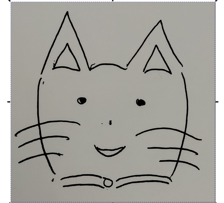
We prepared the following images using Inkscape.

Sample Image
First, launch Inkscape.
When the welcome screen appears, press “New Document” to open a new document.
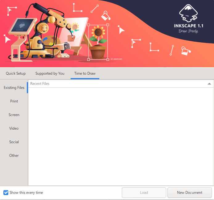
Inkscape Welcome Screen
On the welcome screen, select and open the image.
Select File > Open to select the file.
A screen for specifying DPI, etc., will open here, but in most cases, it is okay to use the default DPI.
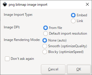
DPI Selection Screen (for PNG)
An image will appear.
Click on this image and select Path > Trace Bitmap.
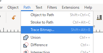
Trace Bitmap
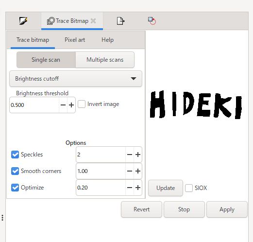
The screen displayed here allows you to select tracing settings and other options.
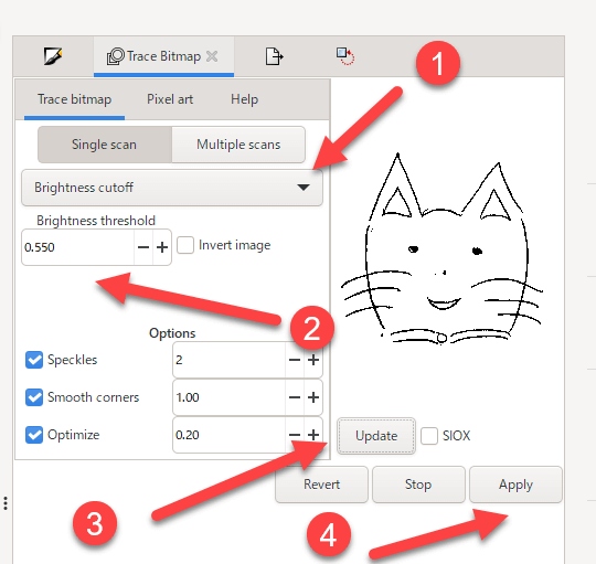
Trace Bitmap Screen
Select the algorithm in the upper drop-down menu (1).
The algorithms vary, depending on style, etc., so choose the setting that produces the best results. “Brightness cutoff,” for example, is a simple method that uses luminance as the base setting. Although there are several settings below “Brightness cutoff,” the “Brightness threshold” (2) is the most important for this algorithm. We recommend using this threshold to find a value that will allow lines to be displayed clearly, while avoiding “noise” other than lines. If necessary, it can also be effective to clean up the image before importing it into Inkscape, using image editing software.
Click the “Update” button (3) to update the preview.
After updating the preview, press “Apply” (4) to add the converted image to the document.
Curve-Transformed Image
After outputting the curve-transformed image, save the output vector image and delete the first loaded image before saving it.
You can tell if an image is selected by viewing the status bar at the bottom of the screen, which says “Image” when you click on the image.
If it is labeled “Path,” the vectorized image is selected.
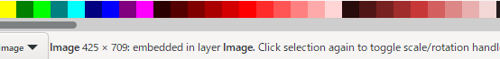
Status Bar Display
Erasing an image removes the original background from the image, leaving only the line drawing.

Image With Only Line Drawings
Now, with just the vectorized image remaining, save the file by selecting File > Save As and choose “Plain SVG” as the file type.
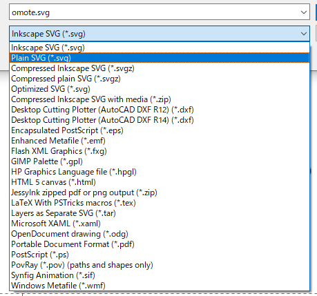
File Types When Saving to Inkscape
You now have a saved scalable vector graphic (SVG) image that can be loaded into Blender, which is the next step!
Note: Please be careful to check copyrights when loading images for tracing.
Working with SVG Files in Blender
Importing SVG Files
Let’s import the SVG file output from tracing in Inkscape into Blender.
In Blender, select File > Import > Scalable Vector Graphics (SVG).
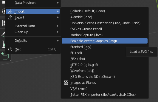
SVG Import Menu
This step will load the SVG file and display the curves.
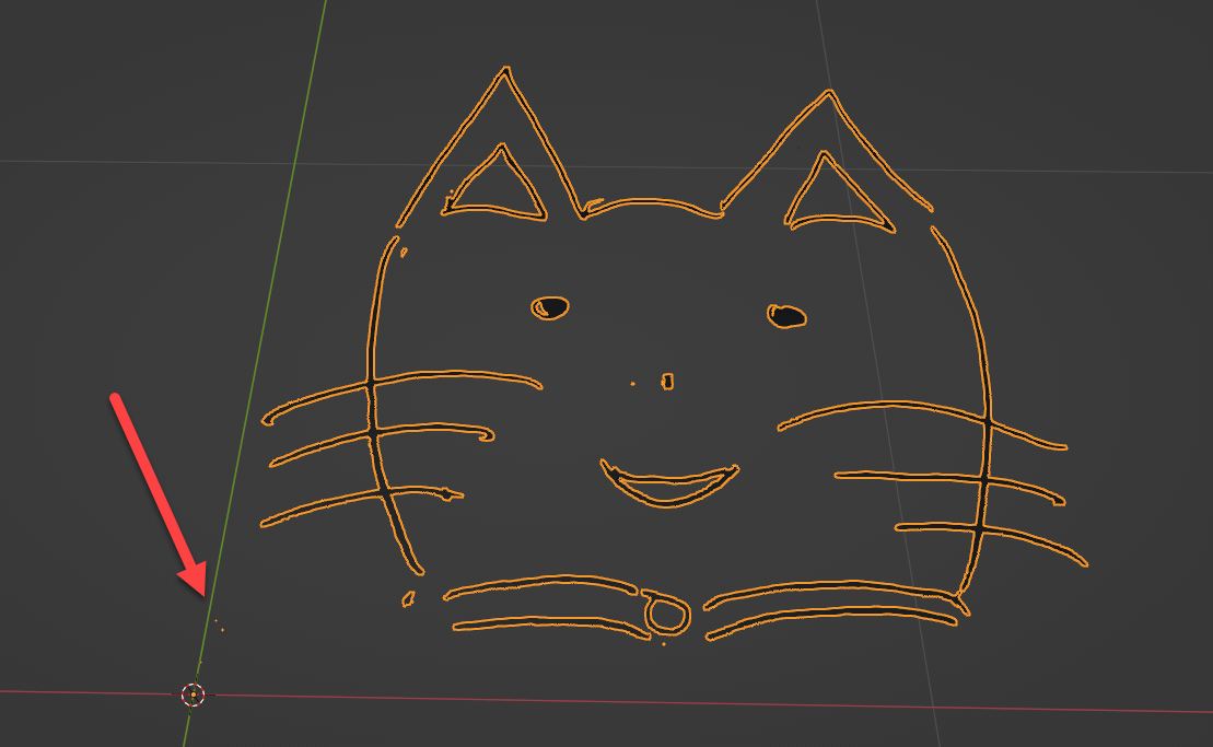
Imported SVG File
Editing Imported SVGs
Cleaning Up
The imported file may show some “garbage,” as indicated by the arrow above. You can clean up this garbage by entering edit mode and erasing.
Editing Curves After Import
In addition, some parts of the image may have unwanted irregularities or wrinkles, which can be edited and corrected in edit mode.
In the image above, control points and handles can be edited using the normal editing operations in Blender (e.g., moving with the [G] key, scaling with the [S] key, rotating with the [R] key, deleting with the [X] key).
Connection of Remote Parts
You may want to connect two separated parts of your image; we describe the steps of this procedure below.
Curve Connection
- Select two or more control points on each side of the curve that you want to connect and press the [X] key to delete the points.
- A pop-up menu will appear. Select “Segments” from the list.
- Note that this step will delete the edges to be connected as well.
- Select the two control points to be connected and press the [F] key to connect them. Do the same for the other pairs of connection points.
- Adjust the positions and handles of the control points as needed.
The second step, “Segments,” is different from the other choice, “Vertices,” in the pop-up menu because Vertices deletes control points, whereas Segments deletes the curve itself.
For a closed curve that constitutes a figure, deleting a vertex will not work well because instead of deleting the curve between the control points, the image will be updated as a figure that does not pass through those control points.
In the video above, after deleting the curve section, we use Vertices to delete the leftover control points.
Thickening
The imported SVG file will be a flat surface with no thickness, so let’s add thickness to it.
To add thickness, use the object properties.
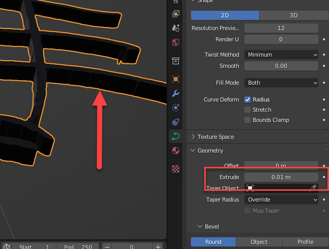
Thickening Setting
You can add thickness by using the “Extrude” setting in the “Geometry” section.
As indicated by the arrow on the left above, the thickness is reflected in real time, so you can see the actual thickness of the image.
Mesh Transformation of Curves in Blender
It is not suitable to output the converted curves as they are.
Curve data cannot be understood by many environments, including STYLY.
As a result, conversion is necessary. Prior to conversion, a resolution is specified.
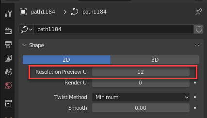
Specify Curve Resolution
In this example, we will be changing the value of “Resolution Preview U.” “Render U” is used when rendering as an image in Blender, so we will not need it in this case.
Specifying Resolution Preview U will change the number of polygons that are used in the mesh conversion: a higher number will result in a more accurate output, but with a higher polygon count; a lower number will result in a rougher but smaller polygon count.
Depending on the complexity of the curve to be converted, some curves can be converted with a resolution of 1, while others require a resolution of up to 5. For circles especially, a lower resolution will result in noticeable choppiness. Since the display is updated in real time, find the resolution that seems just right for your image.
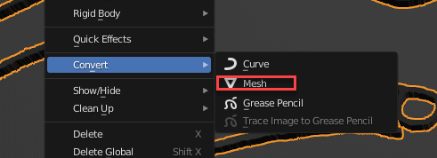
Conversion to Mesh
Conversion to mesh is performed in object mode by selecting Object > Convert > Mesh.
After this conversion, you can output the mesh to FBX or other formats.
Workflow to Use with STYLY
Next, we will make a model of a name logo. We encourage you, the reader, to prepare a paper sketch of your name or other information and try it out.

Sample Image
First, import your sketch as an image. The best way to import an image is to use a scanner, but if you do not have a scanner, take a picture with your smartphone. Be sure to take the picture in conditions, such as a well-lit spot, that allow for you to see as much contrast in the sketch as possible. Low contrast, for example, can bury what you have drawn in noise when you select the brightness threshold.
For our name logo model, we used the image editing software, Krita, to fill in and otherwise process the captured image. In addition, areas of concern, such as bulges in the drawing, were corrected and cleaned up in this process. You can see that the corrected areas are left white in the following image. This is because only black areas are cut out during tracing and whiter areas are ignored.

Edited Scan
Next, open the above image in Inkscape and trace.
Trace Name Sketch
Save the image as an SVG file and import into Blender.
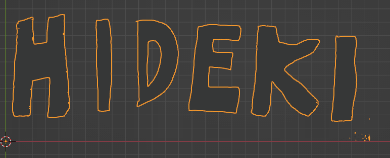
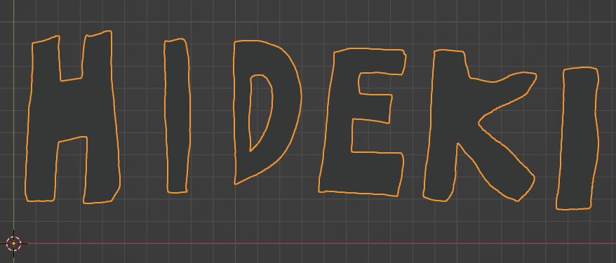
Logo Imported into Blender
Now, you may notice that there are areas of the imported logo that you would like to correct for noise or shape. For example, the edge of the “H” or the bottom of the “D,” or noise that appears in the lower right corner of the image.
Edited Logo
Next, set the thickness for the logo; a thickness of 0.1 meters is specified.

After Setting Thickness and Material
Finally, in addition to thickness, we have set materials, etc., and we added animation separately. Now, we can output this logo as an FBX file and upload it to STYLY.
How to Upload to STYLY
How to create an account:

How to upload to STYLY:
How to upload from Unity to STYLY:
If you have any questions about STYLY, bug reports, or requests for improvements, please contact the STYLY FORUM.
https://en.forum.styly.cc/support/discussions
Using curves and tracings, you can import and use hand-drawn assets as 3D models along with 3D assets. Add accents to your scene with them.