This article describes how to convert text and logos into 3D objects using Blender.
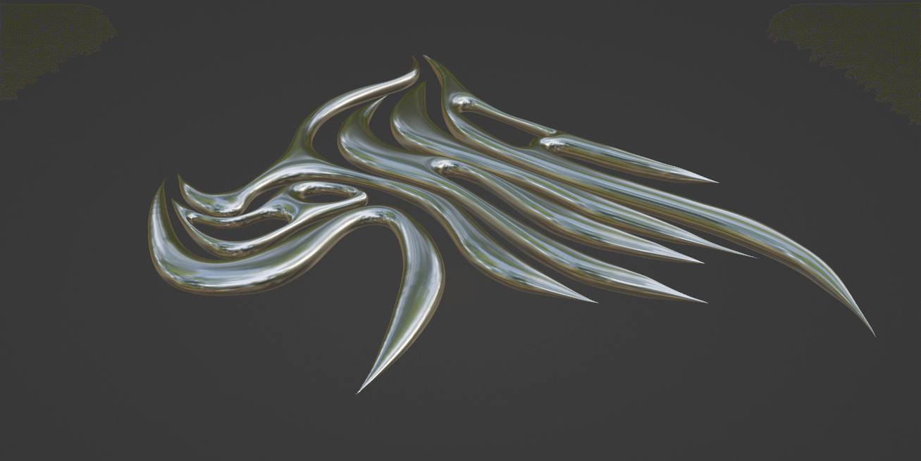
We refer to 3D metallic logos and letters as “chrometypography.”
In this article, we show you how to convert logos and letters created either in Illustrator, using any drawing application, or by hand on paper into 3D using Blender so that you can create them for free, even if you do not have a contract with Illustrator.
The original data used in this example can be downloaded below; please use it if you want to try creating 3D data.
Original data: Download
Illustrator & Blender
When using Illustrator and Blender, logos and text should be created in a drawing application.
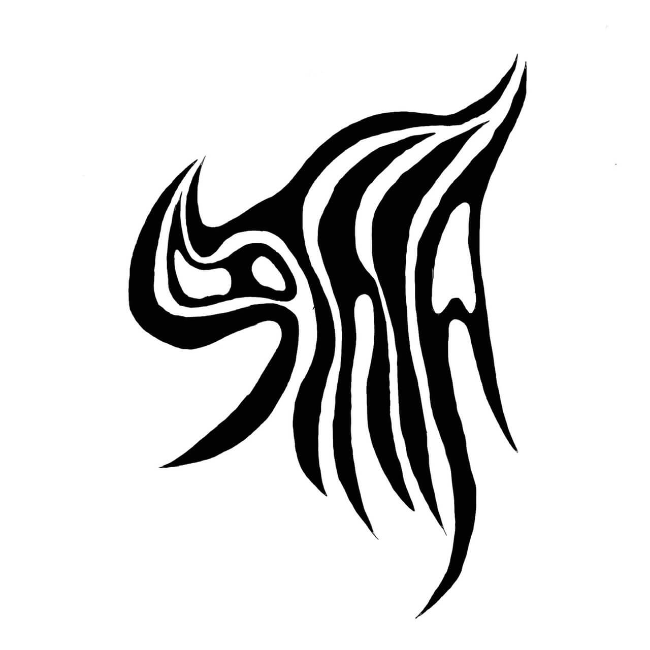
Logo in the shape of the letters STYLY
First, save your drawing application creation in .png or .jpg format and open it in Illustrator.
We used the Art & Illustration template.
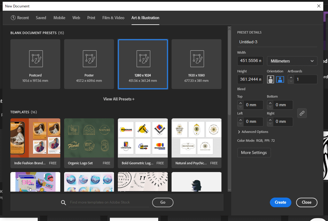
Create a new file in Illustrator
Start Illustrator and click File→Place in the upper lefthand corner to select the image (the background will change to green).
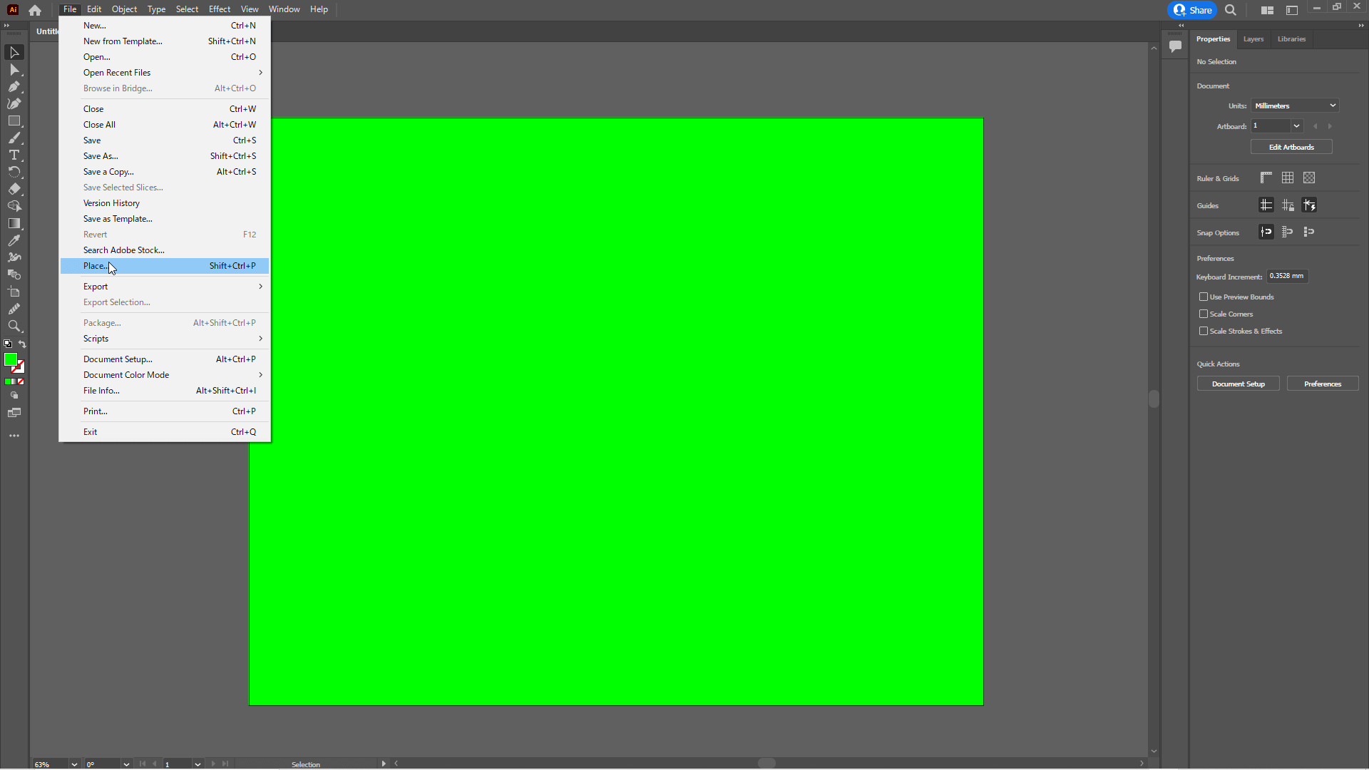
File→Place
Once the image has been added, click on Window→Image Trace at the top of the screen.
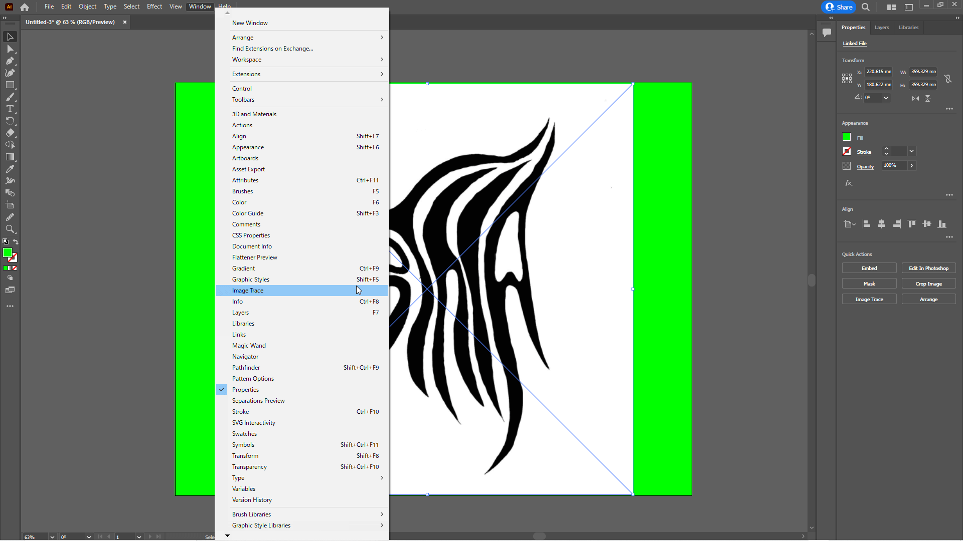
Window→Image Trace
In the Image Trace tab, set Presets to Black and White Logo, uncheck Preview, and click Trace.
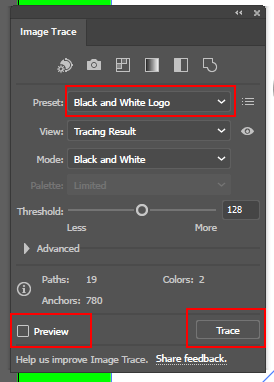
Image Trace settings
After clicking on Trace, the image can be converted to a path by clicking on Expand at the bottom of Properties on the righthand side of the screen.
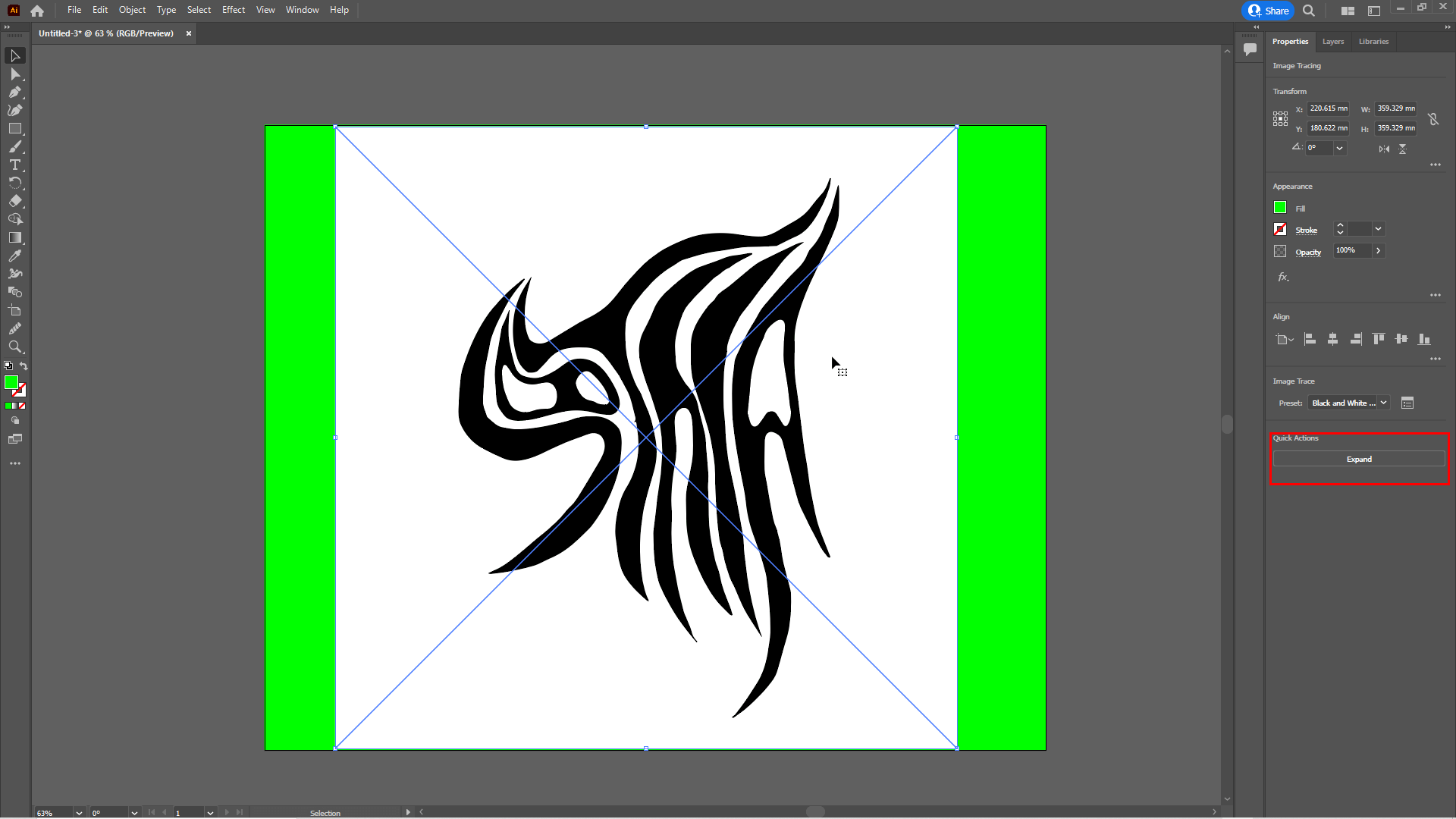
Click on Expand
Delete unnecessary paths and smooth the paths using the Smooth tool.
Remove and smooth unwanted paths.
If you cannot find the Smooth tool, add it from the Edit Toolbar.
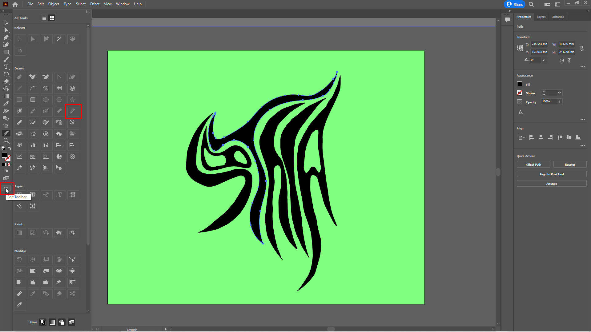
Edit Toolbar→Smooth Tool
When it is smooth, click File→Save As in the upper lefthand corner.
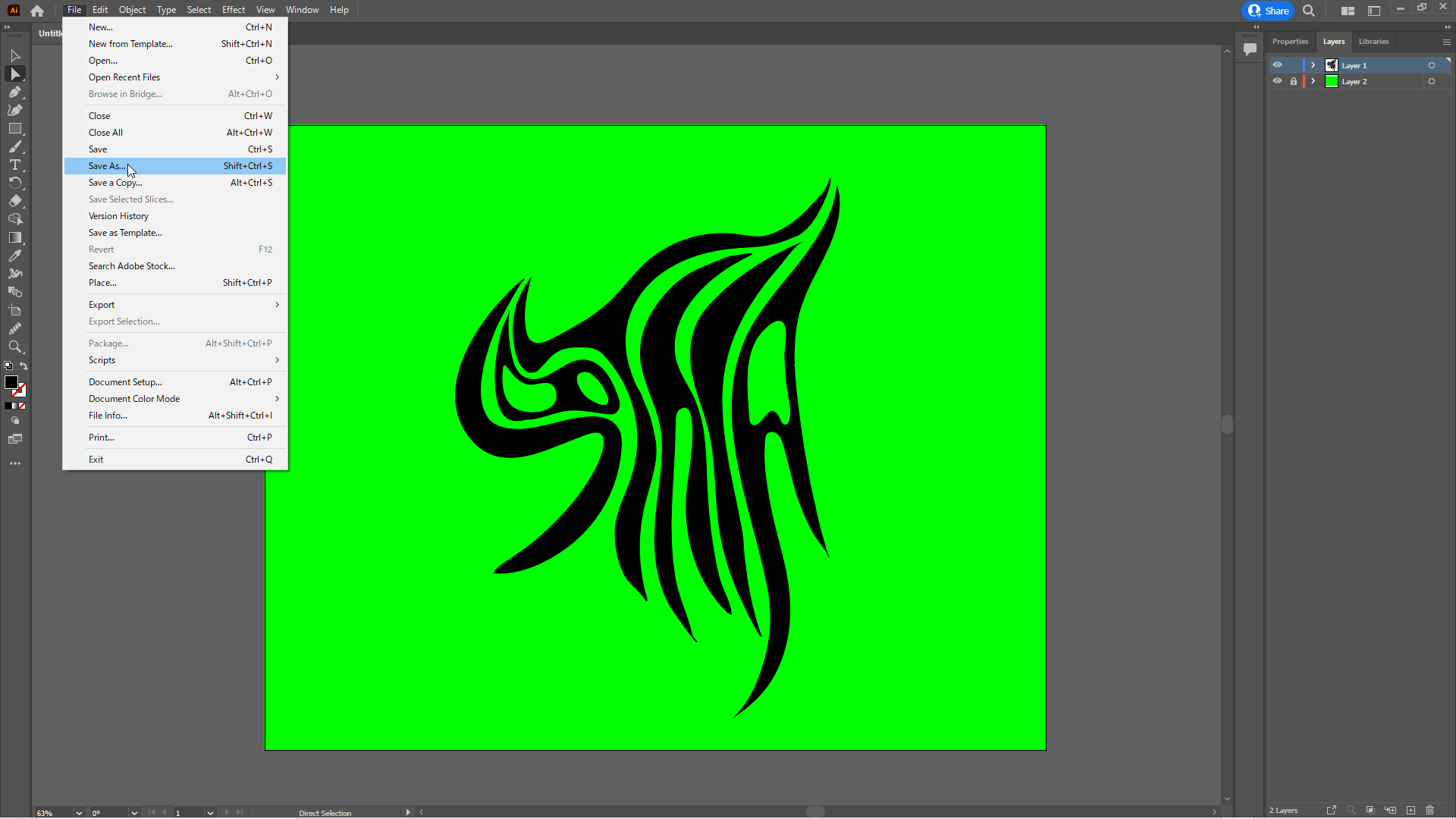
File→Save As
Name the file and save it with SVG as the file type (note that SVGZ format cannot be read by Blender).
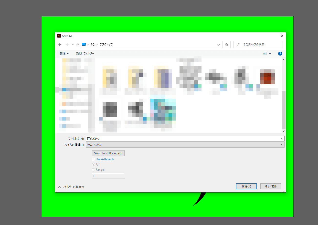
Save as SVG
Blender
Start Blender and delete all objects on the scene, including the camera and lights (this is a process for screen visibility and is not required).

Delete all objects
Click Scalable Vector Graphics(.svg) under File→Import in the upper lefthand corner to import the SVG file you just saved.

File→ImportでScalable Vector Graphics(.svg)
To make it easier to work with the objects as they are divided into their parts, select all the objects and merge them using the [ctrl]+[J] keys.
![ctrl+[J]キーで統合します](https://styly.cc/wp-content/uploads/2022/06/13.gif)
Press [ctrl]+[J] to merge
The material assigned from the beginning will be difficult to see and should be removed.
Delete material
Next, add thickness.
Select the object and open the Object Data Properties tab and click on Geometry.
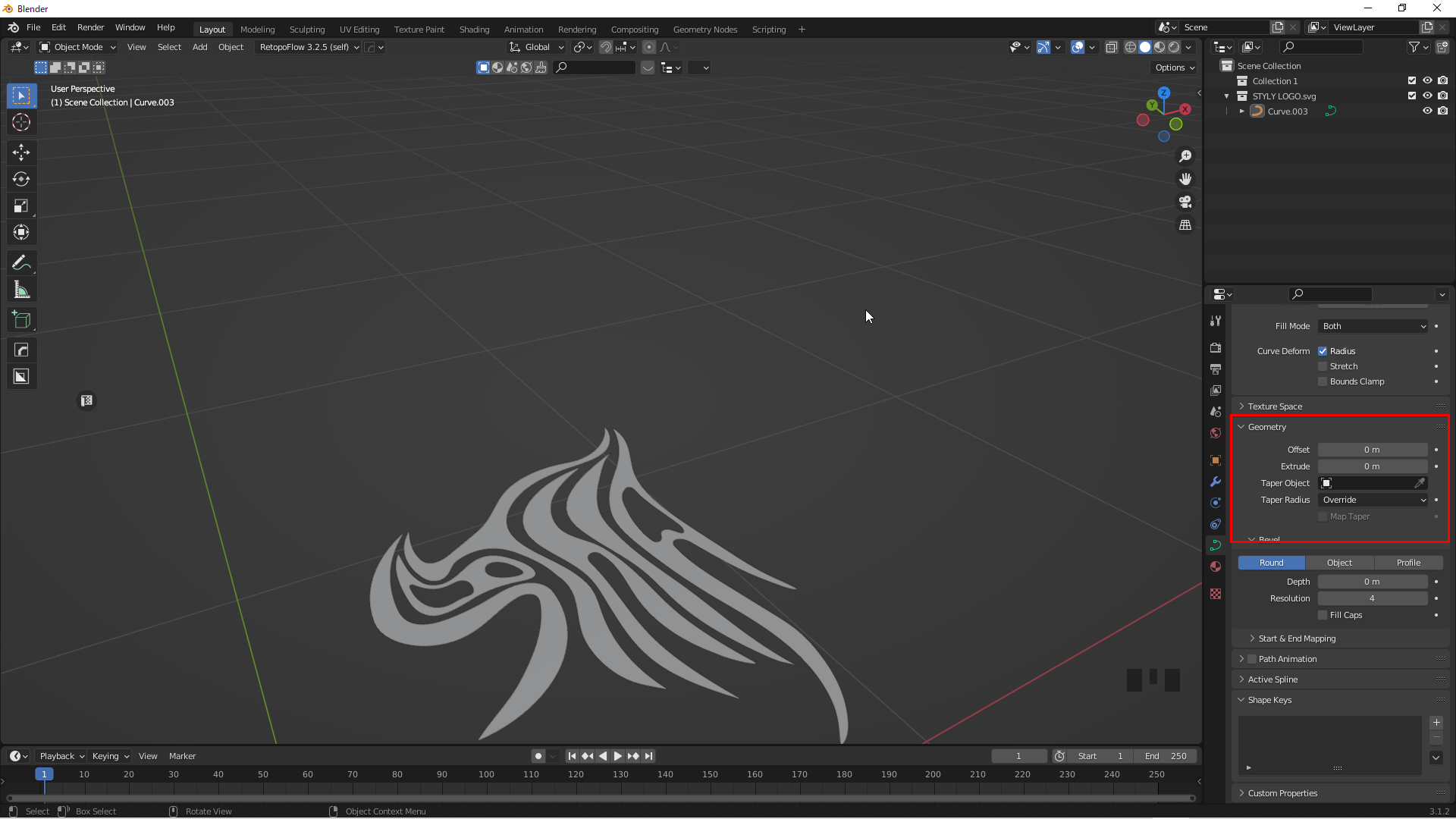
Object Data Properties→Geometry
The thickness can be adjusted by changing the value of Extrude in Geometry.

Thickness can be adjusted with Extrude
The thickness can be changed later; we set the Extrude value to 0.02.
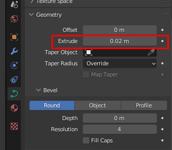
Extrude 0.02
Select an object, right-click, and click on Convert To→Mesh to change it from a curve to a mesh.
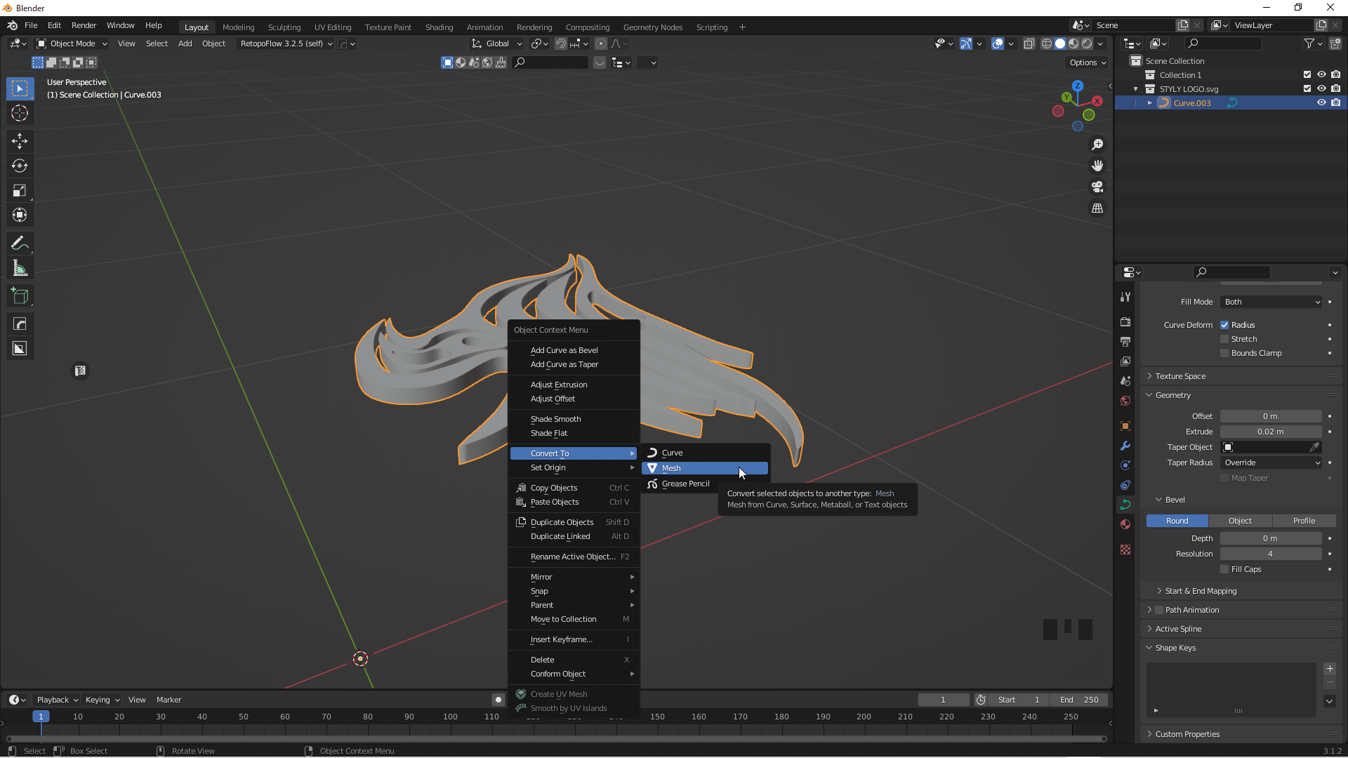
Convert To→Mesh
The following process is divided into two patterns, one for a rounded shape and the other to leave some corners.
Pattern 1: If You Want to Keep the Corners
Add a Remesh modifier to align the object’s mesh.
From the Modifier Properties tab, add Remesh and change the Voxel Size to 0.001.
Modifier Properties→Remesh→Voxel Size to 0.001
Click Apply when you can add it.
Apply
Go to the Sculpting window and smooth the surface with the Sculpt function.
Select the Smooth brush and change Strength to 1.
You can change the thickness of the brush using Radius.
You can use any thickness you like; we set it to 195px.
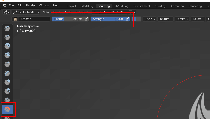
Change the value
Activate the Z-axis of the mesh symmetry and apply brushes all over to make them smoother.
Smoothing
Once we have achieved a certain degree of roundness, we can move to the Shading window and add a material.
Select the object and add a new material.
We set the Metalic value to 1 and the Roughness value to 0.15.

Metalic=1、Roughness=0.15
The object is now complete.
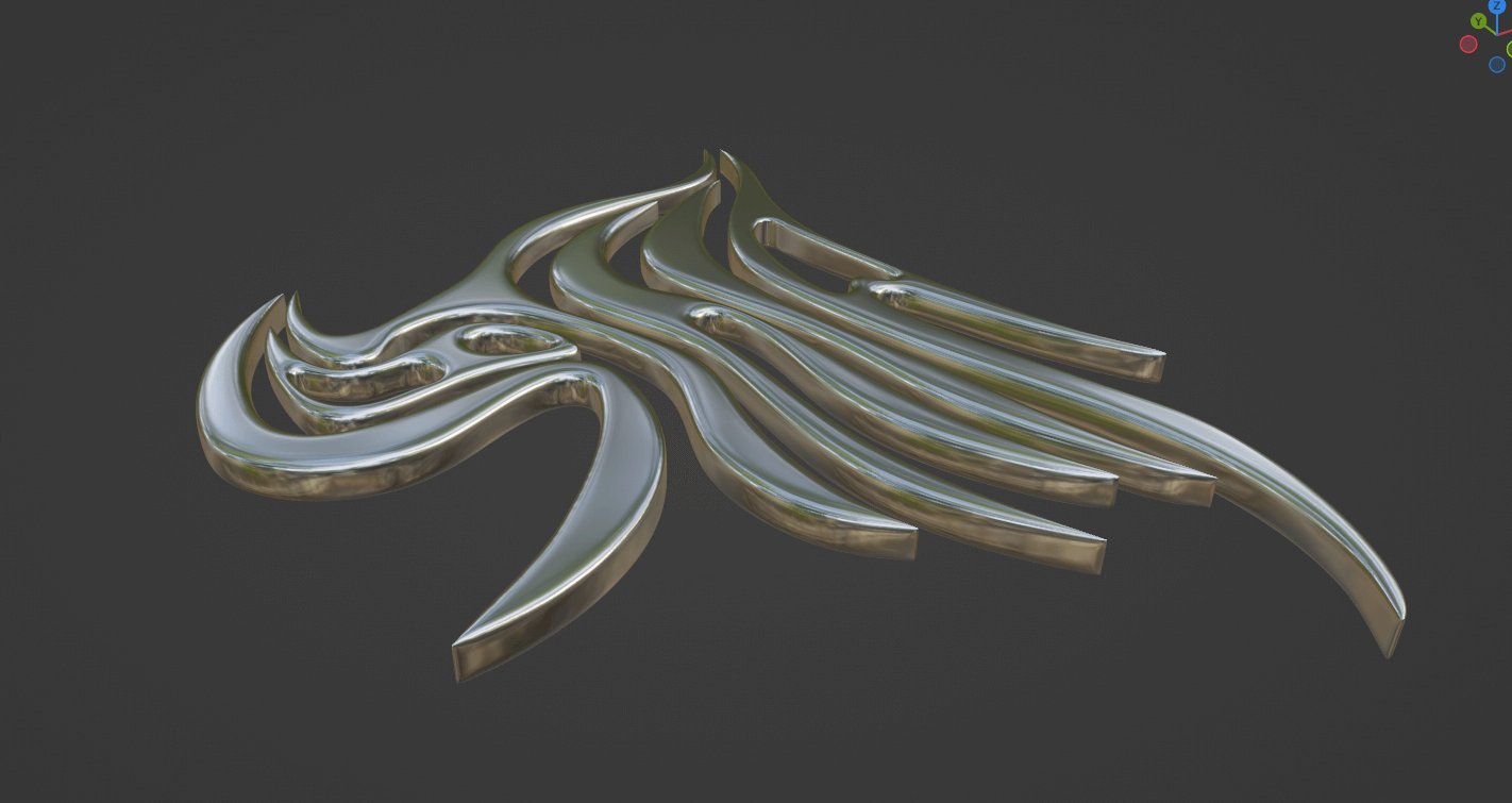
The object is complete
Pattern 2: If You Want to Make it Rounded
If you want to make it rounded, do not use the [ctrl]+[J] keys when importing the SVG to merge it; adjust the thickness in the Geometry section of the Object Data Properties tab for each part.
Change the size of the edges to make them nice and sharp.
Select the part with corners, enter edit mode and activate Proportional Editing at the top of the screen.
Enable Proportional Editing
Select the edge around the tip of the corner, press the [S] key to enter scaling mode, and press the [Z] key to change the size of the Z-axis. Press the number 0 to set the size to 0.
The Proportional Editing influence range can be changed using the mouse wheel.
If the gray circle indicating the area of influence is not displayed, the size may be too large, out of the screen, or too small. Move the mouse wheel to check the size.
![[S]キー→[Z]キー→大きさを0にします](https://styly.cc/wp-content/uploads/2022/06/25.gif)
[S]key→[Z]key→Set the size to 0
In Proportional Editing mode, the mouse wheel can be moved to adjust the range of scaling so that sharp edges are smoothed out as much as possible.
This operation should be performed on all sharp edges.

Perform on all sharp edges
Once adjusted, merge all parts by pressing [ctrl]+[J] and complete the same process as for Pattern 1.
When smoothing the surface with the sculpting function, apply a brush so that the angular parts are eliminated. The process is then complete.
The rounded shape is completed
For Handwriting and Drawing Applications
If hand-drawn, take a picture. If written in an application, save it as an image (in both cases, white lines are easier to see when drawing curves later in Blender).
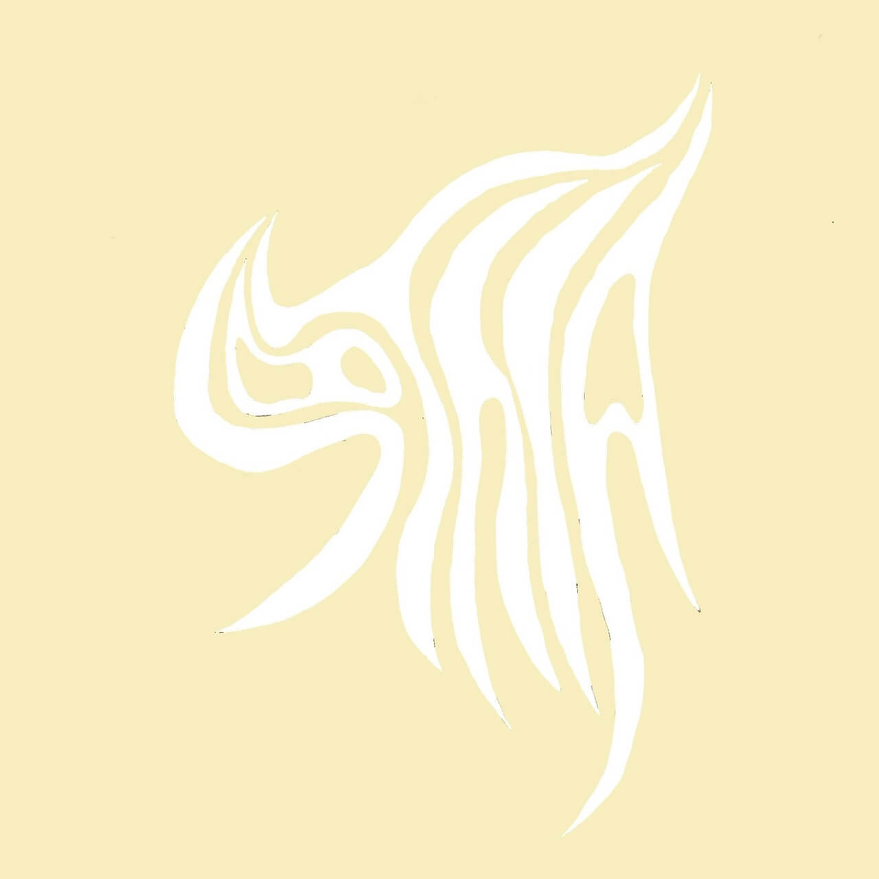
White lines are easier to see when drawing curves later
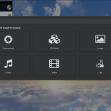
Start Blender, set the viewpoint to Z, click Add→Image→Reference in the upper lefthand corner, and add the saved image (if the image is tilted, set Rotation to 0 from Object Properties).

Add→Image→Reference
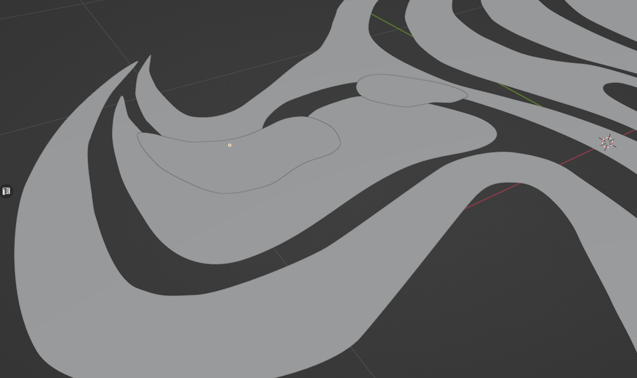
Place Bezier curves to trace the contours of the image placed in the scene.
Add a Bezier curve with Curve→Bezier by pressing [Shift]+[A].
![Shift+[A]キーでCurve→Bezier](https://styly.cc/wp-content/uploads/2022/06/30.png)
Curve→Bezier with [Shift]+[A] key
In edit mode, move the Bezier curve and place it along the contour.
Bezier curves can be moved with the [G] key and rotated with the [R] key; new handles can be added with the [E] key.

Move the Bezier curve and place it along the contour
Once the Bezier curve has been placed all the way around the contour, you can select both the first and last handles and merge them by pressing the [F] key.
![[F]キーで統合することができます](https://styly.cc/wp-content/uploads/2022/06/32.gif)
You can merge them with the [F] key
Select a Bezier curve and increase the Resolution Preview value in Object Data Properties to make the curve smoother.
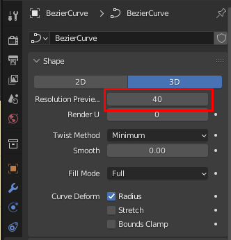
Object Data Properties→Resolution Preview
Once all curves have been placed, return to Object Mode, select the Bezier curve, right-click on it, and click on Convert To→Mesh to change it from a curve to a mesh.
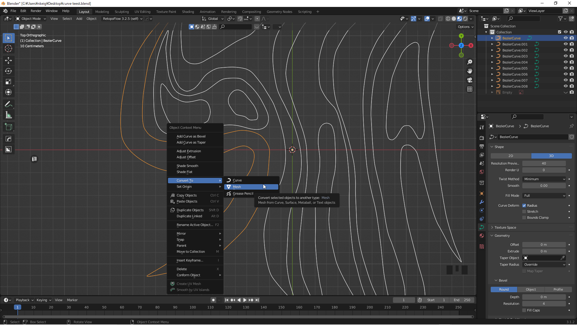
Convert To→Mesh
Selecting an object in edit mode and pressing the [F] key fills the mesh.
![[F]キーを押すとメッシュが埋まります](https://styly.cc/wp-content/uploads/2022/06/35.gif)
Pressing the [F] key fills the mesh
The holes should also be filled in and moved up in the Z axis for clarity.
Leave the holes moved up
Enter the edit mode, merge them with [ctrl]+[J] keys except where the hole will be, select the face, and press the [E] key to extrude the mesh by 0.05.
![ctrl+[J]キーで統合し、面を選択して[E]キーでメッシュを0.05押し出します](https://styly.cc/wp-content/uploads/2022/06/37.gif)
Press [ctrl]+[J] to merge, select a face, and press [E] to extrude the mesh by 0.05
Use a boolean modifier to integrate the hole area to drill the hole and extrude it so that it is thicker than the other areas.

Press out the hole
Add a boolean modifier to the logo body part and make a hole.
Specify the mesh of the hole in the Object and set the Solver to Fast.

Add a boolean modifier
A thick mesh has been created.
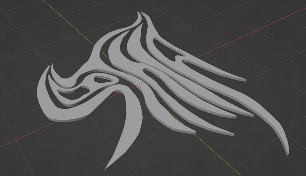
A hole has been made
For the process from here on, please refer to the aforementioned Pattern 1: To leave corners and Pattern 2: To round off the shape.
If you are using Pattern 2, please press the [P] key in edit mode to separate the object into its parts in advance.
![編集モードで[P]キーを押して各パーツに分離します](https://styly.cc/wp-content/uploads/2022/06/41.gif)
In edit mode, press the [P] key to separate each part
Make the Font 3D
From here, we can create chrometypography using existing fonts.
Add text by pressing [Shift]+[A] on the Blender scene and clicking on Text.
![Shift+[A]キー→Text](https://styly.cc/wp-content/uploads/2022/06/42.gif)
Shift+[A] key→Text
You can change the font by clicking on Font in Object Data Properties. Click the File button to the right of Regular and add the font you want.
Here you will see the standard fonts that come with Windows.
No installed fonts are displayed by default
If you wish to use your own downloaded fonts, enter the file path as
C:\Users\username\AppData\Local\Microsoft\Windows\Fonts
to open the location where the downloaded fonts are stored.
Enter your PC user name in the “User Name” field.
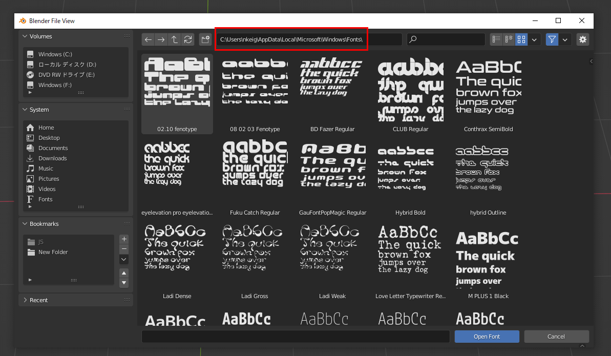
C:\Users\username\AppData\Local\Microsoft\Windows\Fonts
If you want to open the font storage location by following the file instead of entering the file path, click on the triangle in the upper righthand corner and check Show Hidden so that the hidden file can be displayed.
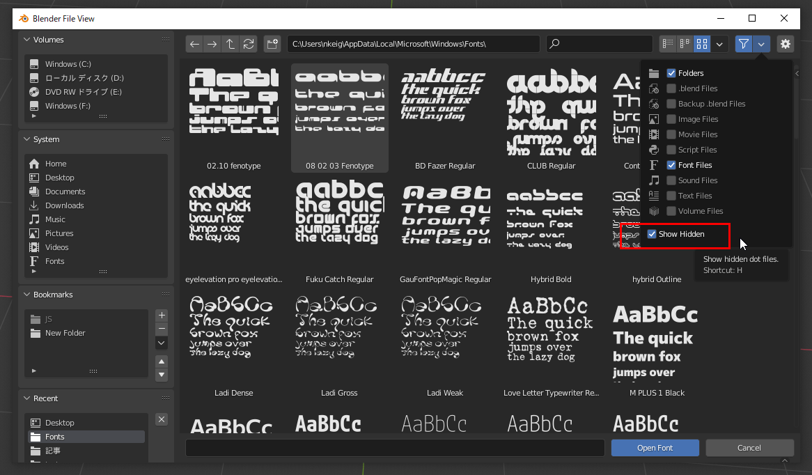
Check Show Hidden so that hidden files can be displayed
Clicking on a font file changes the font in Blender.
To change the text content, select the text object and enter edit mode.

You can change the text by entering edit mode
Object Data Properties, Geometry→Extrude can be used to change the thickness. Spacing→Character Spacing can be used to change the spacing between characters.
We set the value for Extrude to 0.02.

You can change the values in the Geometry section of Object Data Properties
Select a text object, right-click, and click Convert To→Mesh to change it from text to mesh.
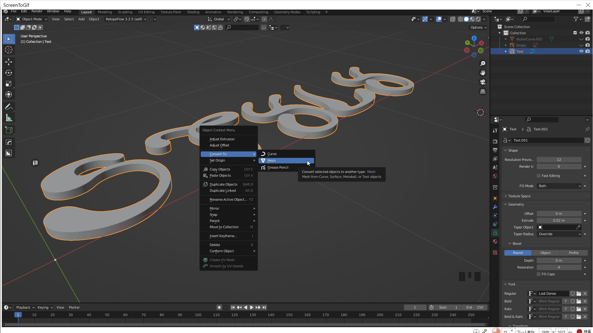
Convert To→Mesh
For the process from here on, please refer to the aforementioned Pattern 1: To leave corners and Pattern 2: To round off the shape.
If you are using Pattern 2, please separate the object into its parts in edit mode beforehand.
The “Ladi” font used in this project can be downloaded from here:
Ladi Display Font: Download
Export FBX
Select the object you want to export and choose File→Export→FBX in the upper lefthand corner.
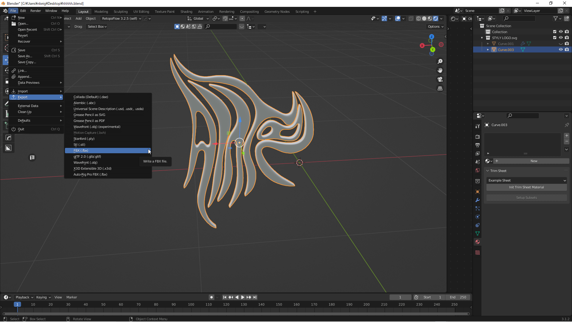
File→Export→FBX
Set the export settings as shown in the image, select the destination folder, and click Export FBX.
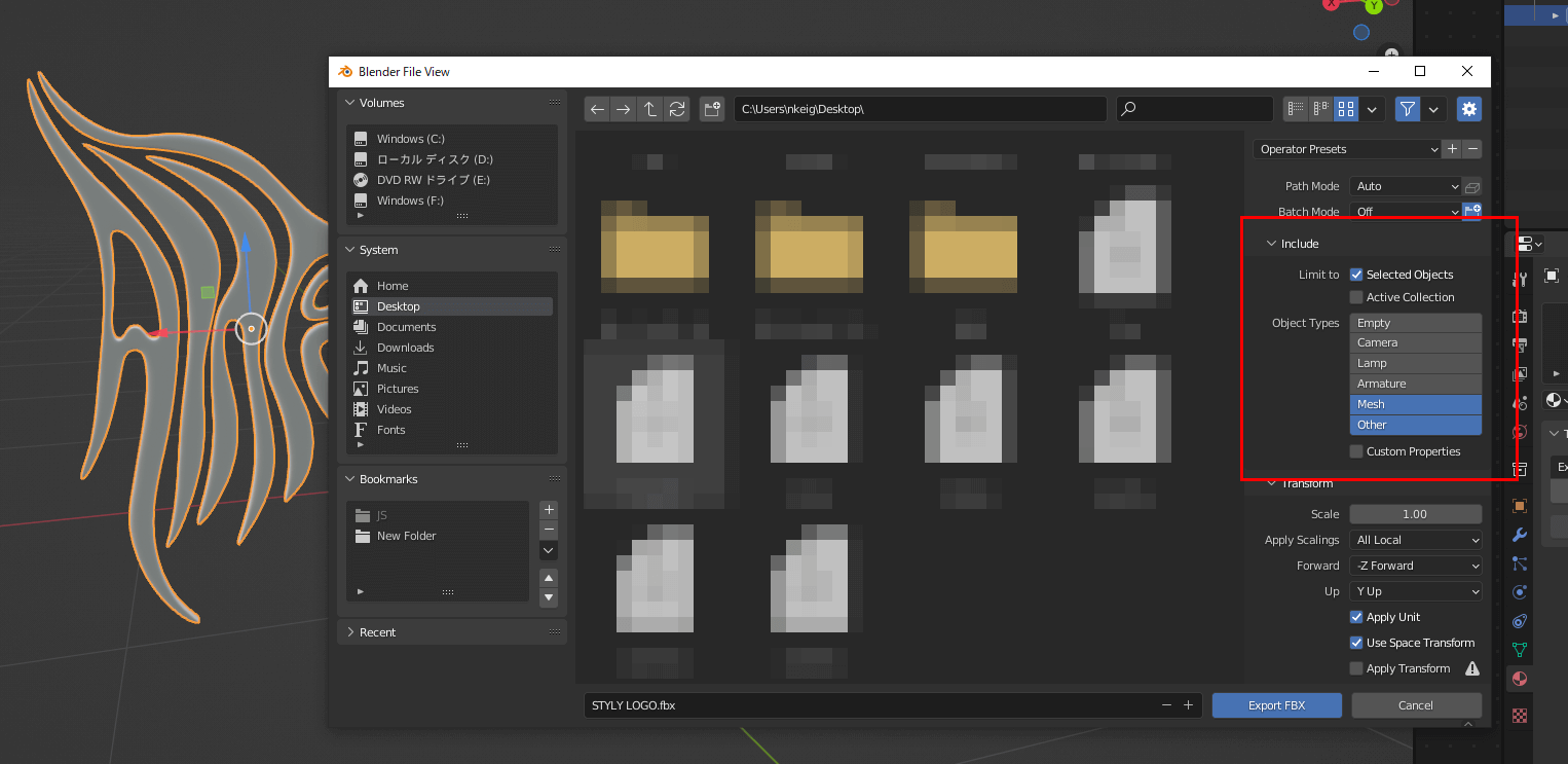
Export FBX
The object is now complete.
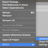
How to Upload to STYLY
How to create an account:

How to upload to STYLY:
How to upload from Unity to STYLY:
Once the 3D model is placed as an object, it will appear as shown below.
This completes the upload to STYLY.
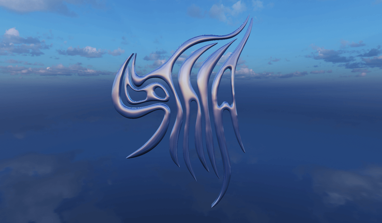
Placed on STYLY
If you have any questions about STYLY, bug reports, or requests for improvements, please contact the STYLY FORUM.
https://en.forum.styly.cc/support/discussions
Certified (QA) by Shota Shawn Yoshizawa
Edited by SASAnishiki
Translated by Sho Ishiwata