In this article, I will explain how to use techniques such as bump mapping and normal mapping in Blender to create 3D models with a more three-dimensional feel.
What is Bump Mapping?
If you look up the definition of bump mapping, you will find that it is written as follows
レンダリングするオブジェクトの面の法線に対する揺らぎをハイトマップ(高低マップ)で調べて、光源計算の完了前に各ピクセルに対して適用する、CGの技術である。
Source: Bump mapping – Wikipedia
Simply put, by specifying a height map that has height and low information in addition to the normal texture for an object, it is possible to create pseudo shadows and highlights, and express a sense of unevenness in terms of appearance even if the mesh is not uneven.
The heightmap for bump mapping uses a grayscale image.
White represents high areas and black represents low areas.
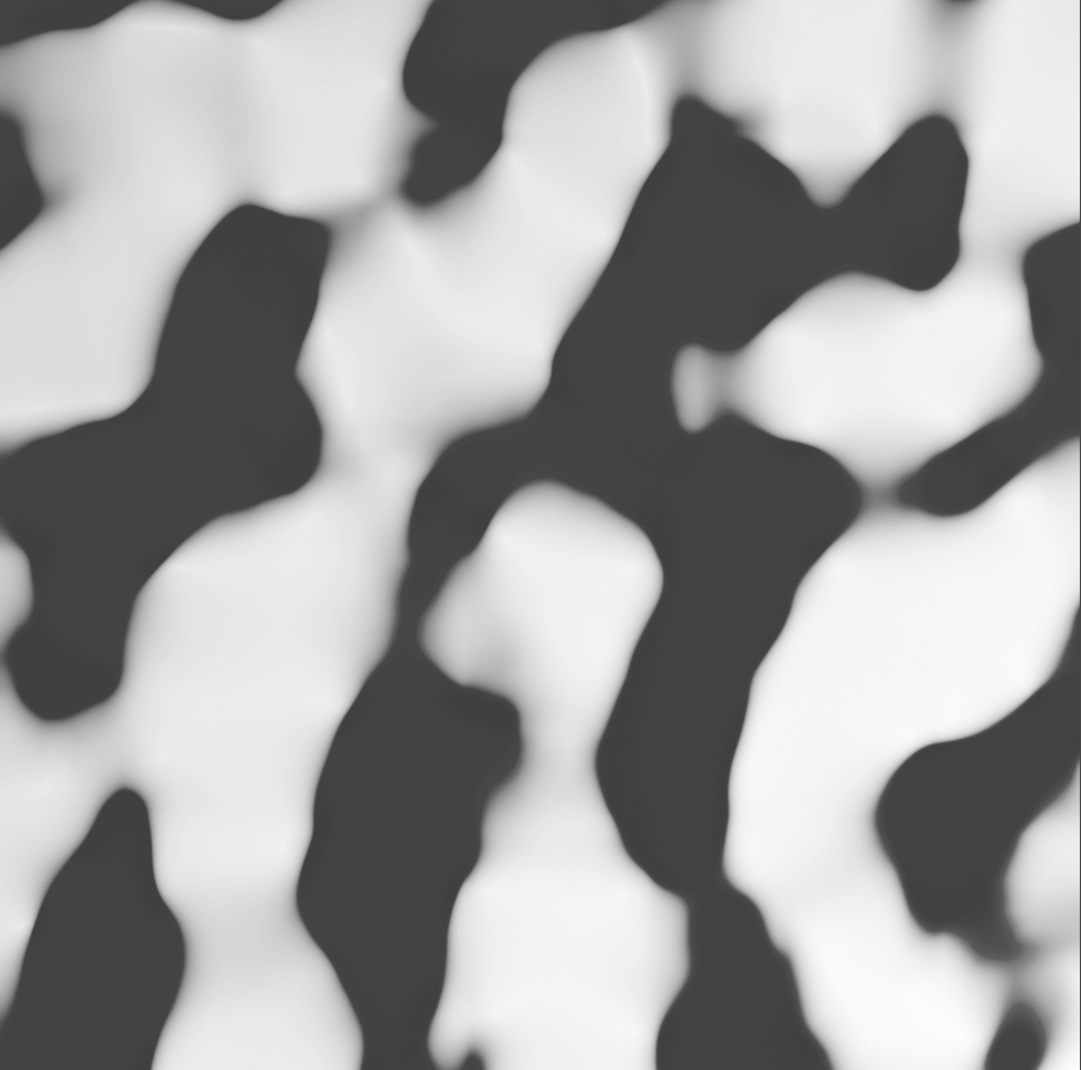
Example of a height map
What is normal mapping?
Nowadays, normal mapping, which is more advanced than bump mapping, is often used.
Bump mapping can also represent height differences, but in reality, the way highlights are applied depends on the normals.
In other words, by using normal information, it is possible to express more detailed unevenness.
Normal maps used for normal mapping often use the colors light blue, purple, and pink, as shown below.

Example of a normal map
While the height map holds only the height information, the normal map stores the XYZ value of which direction the surface is facing (normal vector) in pixels as color information.
The X component of the normal vector (-1.0~1.0) is red (0~255), the Y component is green, and the Z component is blue, but since the plane always faces the Z+ direction, the Z component is stronger and basically closer to blue.
For more details, please refer to the following article.
Practice: Expressing unevenness with a bump map
First, let’s add a plane.
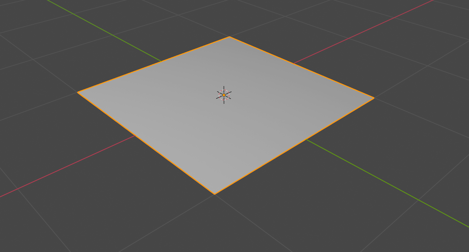
Add a plane
Add a new material.
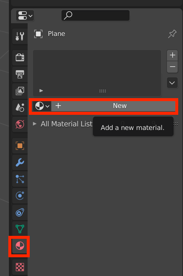
Add a new material
Scroll down and set “Bump” for Normal and “Musgrave Texture” for Height.
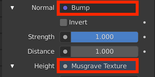
Set Normal and Height
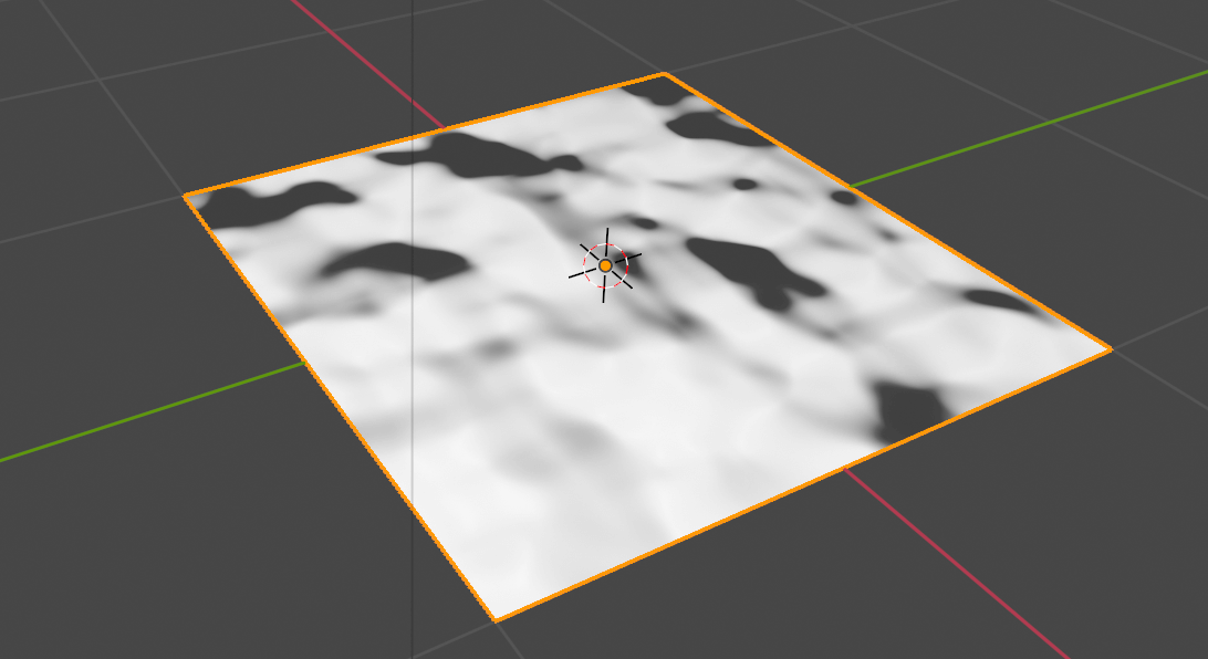
The Musgrave Texture is a texture that produces complex noise as shown below.
In this case, we set this texture for Height, which will make the white areas of this pattern higher and the black areas lower on the plane.

Applying the Musgrave Texture
Let’s try moving the light with the Viewport Shading set to Material Preview.
You can see that the shadows are moving according to the unevenness of the imaginary surface.
Move the light to see the unevenness.
If you switch to the Shader Editor, you will see that nodes like the one below are automatically generated.
(If you do not know how to use the Shader Editor, please refer to the following article.)
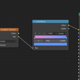
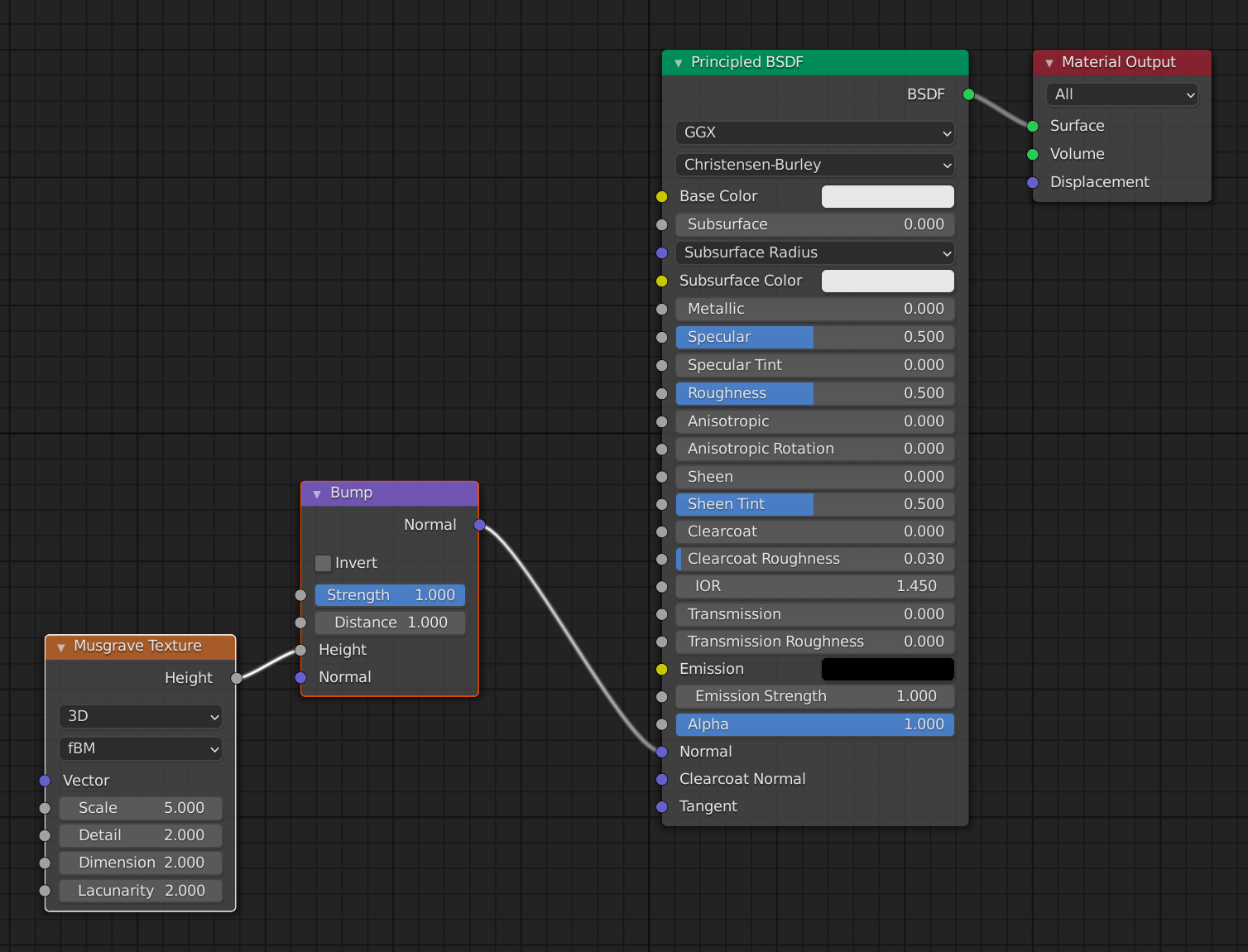
Nodes are generated automatically.
If you lower the Strength value of the Bump node here, the unevenness will become less pronounced.
Lowering the Strength value
It is easier to understand if you add an Image Texture node to the Base Color of the Principled BSDF and set the texture of the cloth.
The texture for this project was borrowed from the following website.
![[Free Texture Material Site] How to Use FreeStockTextures.com](https://styly.cc/wp-content/uploads/2019/09/admin-ajax-3-1-160x160.png)
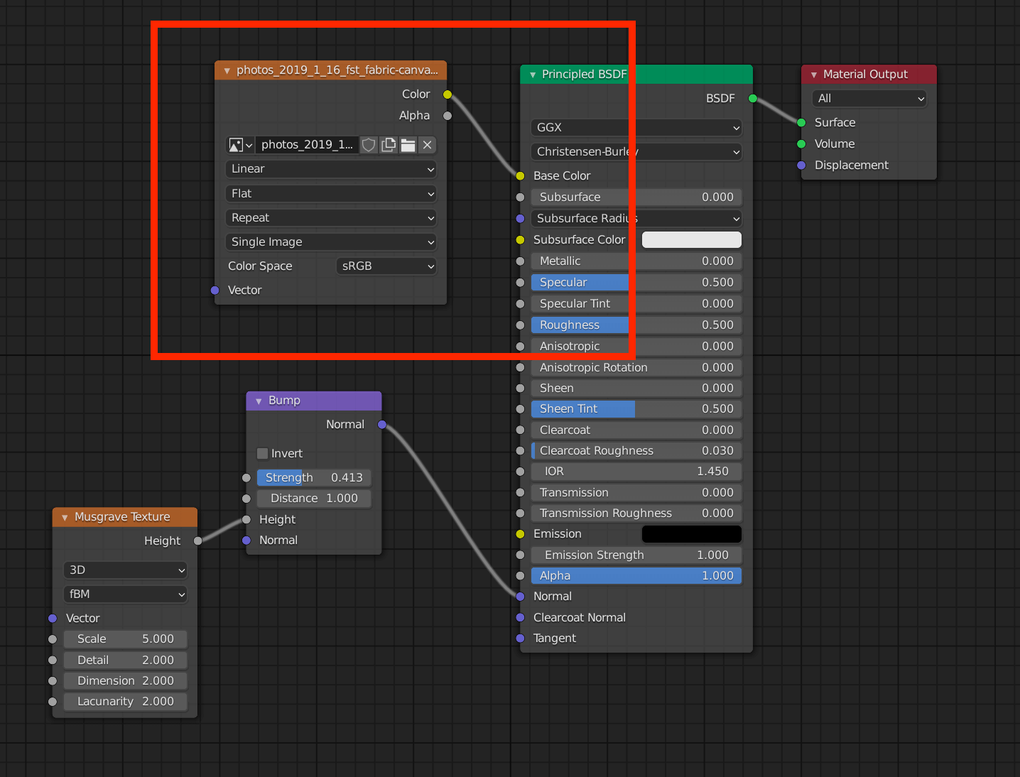
Add an Image Texture for the cloth

Without normal map
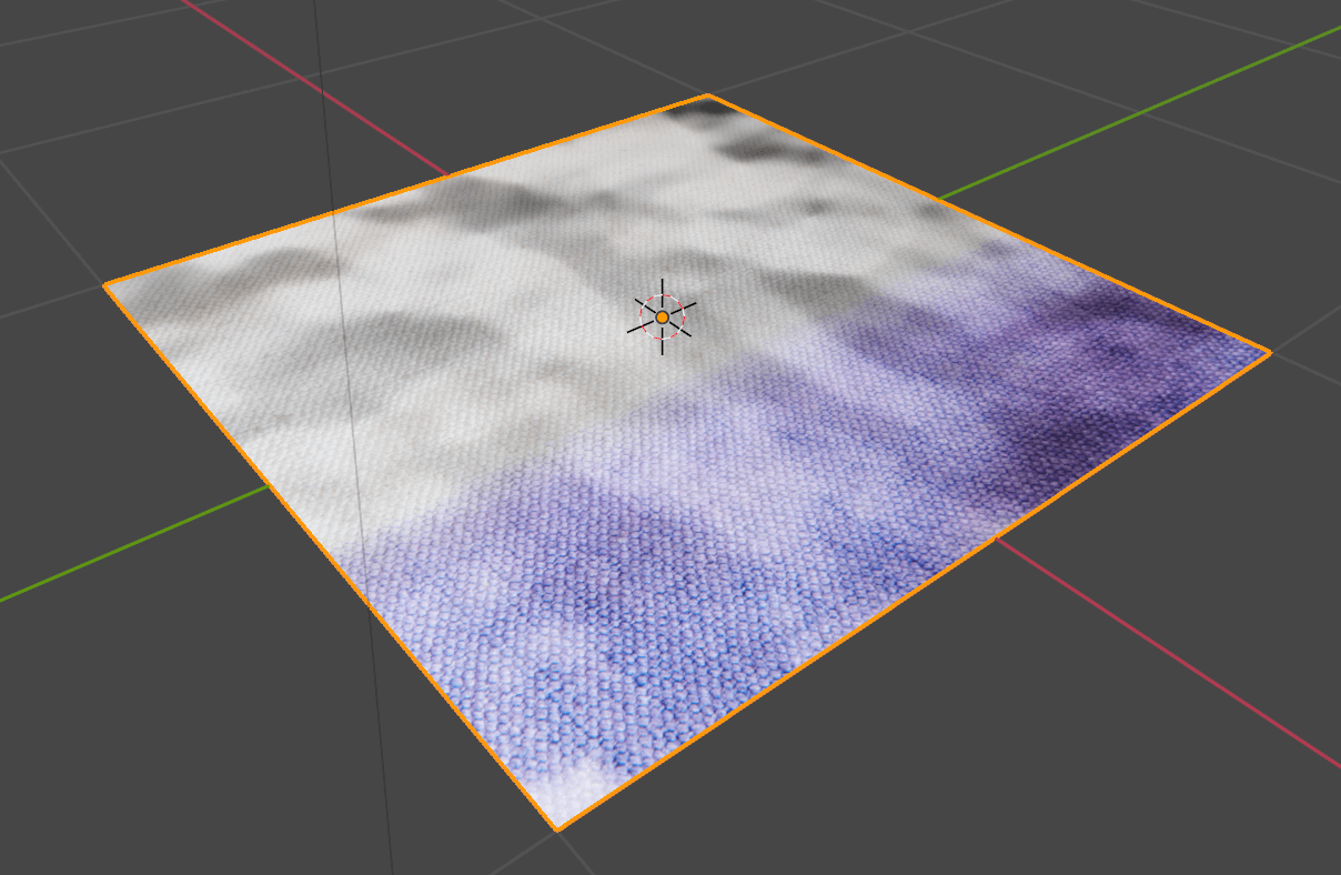
With normal map: wrinkles of the cloth are expressed.
The wrinkles of the cloth are well expressed.
Note that we are using the Musgrave Texture for the Bump, but you can use any image texture by changing it to an Image Texture node.
Practice: Expressing a sense of unevenness with a normal map
This time, we will prepare an image texture and a normal map texture created from it. (See the end of this article for more information on how to create a normal map.)
The textures for this project were borrowed from the following website.
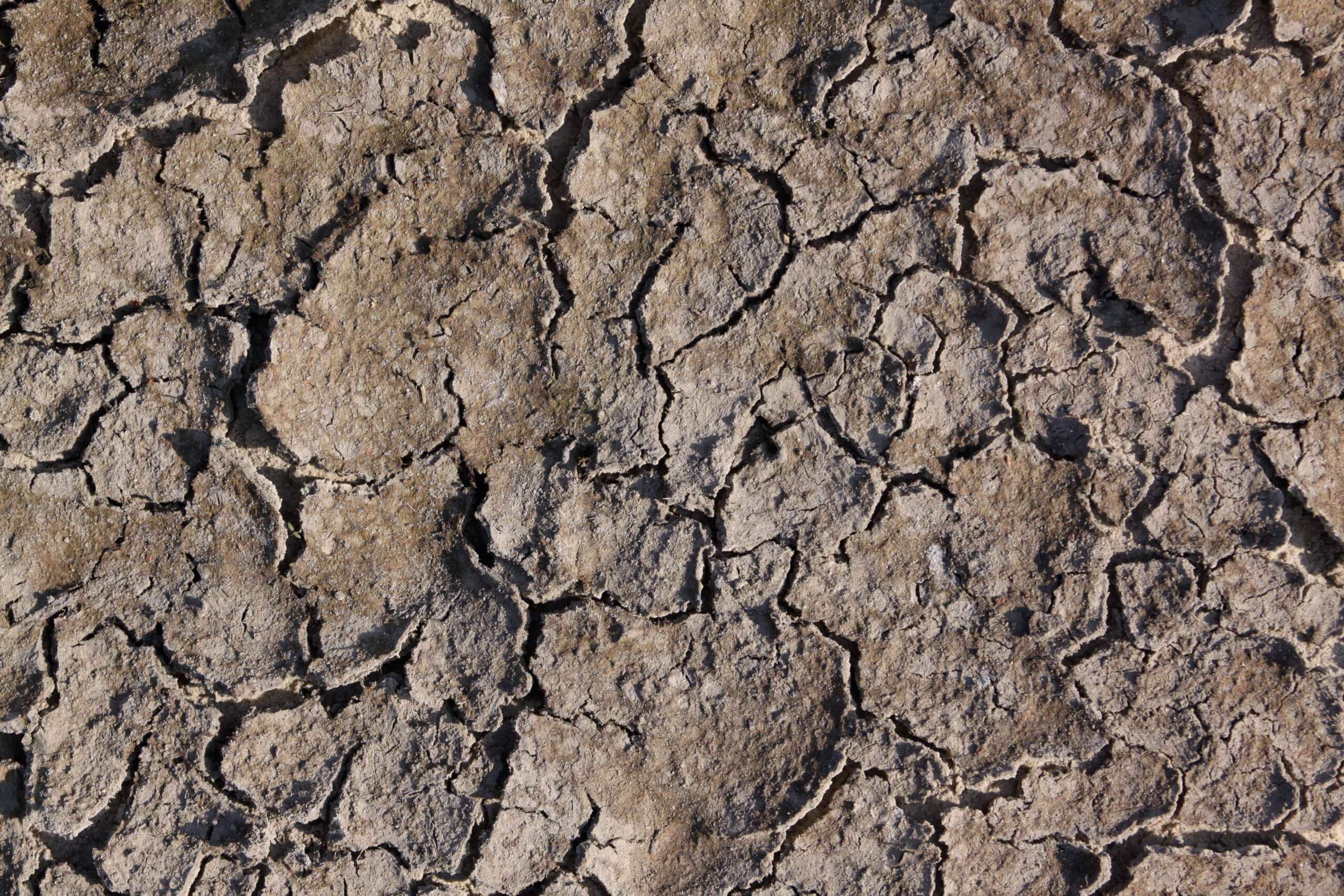
Image textures
Normal map created based on the image texture
The normal map will be set up in the Shader Editor.
Based on the node described in the Bump Mapping section, change the node connected to Normal in the Principled BSDF from Bump to Normal Map, and connect the Image Texture node to the Color of the Normal Map node.
From the folder icon of this Image Texture node, set the normal map image and change the Color Space to “Non-Color”.
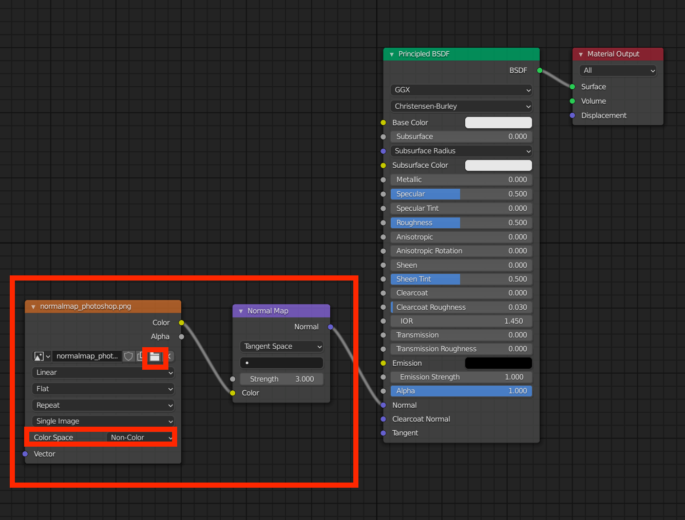
Normal Map node
This is how the unevenness is displayed.
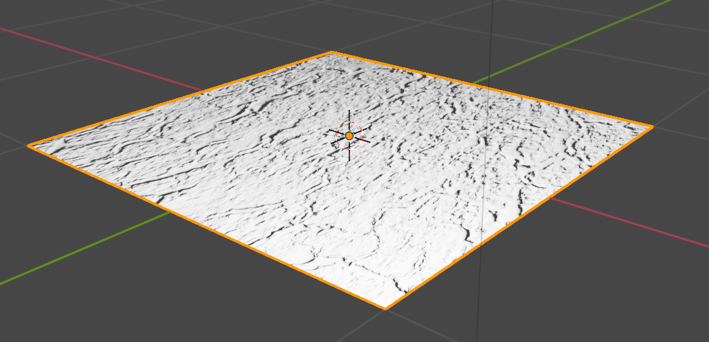
Bumps are now reproduced.
As in the Bump Mapping section, it is easier to understand if you add an Image Texture node to the Base Color of the Principled BSDF and set the original image texture.
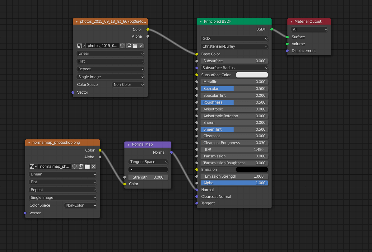
Setting the Image Texture to Base Color

Bumps and bumps can be seen more clearly.
How to create a normal map
There are several ways to create a normal map.
Create it in Photoshop
You can create a normal map using an image editing application such as Photoshop.
For details, please refer to the following article.
Create with an image generator
You can quickly create a normal map by using an image generator available on the web.
Just visit the following website, drag and drop the original image, and the normal map will be created automatically.
http://cpetry.github.io/NormalMap-Online/
However, the quality may not be as good as the one created in Photoshop, so please use it depending on the situation.
Bake a normal map in Blender
In the above two methods, the normal map was created based on the original image texture, but you can also create a normal map by baking the unevenness of the object created in Blender.
I will write about this method later.
How to upload to STYLY
Let’s upload your 3D model to STYLY by outputting it in glTF format from Blender.
Create a STYLY account
How to create an account

How to upload to STYLY
On the left is the plane without normal map, and on the right is the plane with normal map applied.
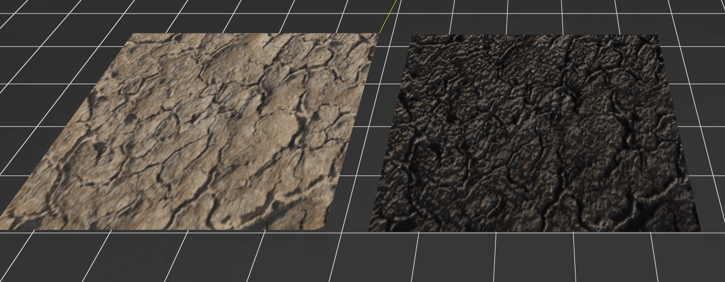
Note that the appearance is quite different from what you see in Blender.
It is hard to see that the normal map is applied just by looking at the plane, but let’s rotate it.

You can see that the flat surface on the right is shaded depending on the direction you look at it, giving it a more three-dimensional and uneven appearance.
You can experience this scene here.