Blender can be used to create a wide variety of VR architectural designs.
This article will explain how to create VR architecture utilizing Blender features such as origin and snapping, and how to create assets from photographs as an application.
Architectural Concepts Done in Blender
Creating buildings could be said to be one of the most exciting aspects of modeling for VR. Creating in VR can also allow for the flexible construction of buildings of a scale that would be difficult to construct in the real world, and three of the most exciting aspects are the following. We can:
- Enjoy building buildings on a scale that is impossible to construct in the real world due to cost and other issues.
- Design buildings with fantasy elements, such as shapes that are impossible to construct in the real world due to physical constraints.
- Visualize the actual building before it is constructed.
Regarding the last point, professionals use CAD and other methods to create architectural drawings, but I think software tools can also be used for communication when conveying an image as an ordering party, for example in the conceptual stage of construction. In addition, using STYLY, it is possible to place buildings not only in VR but also in AR scenes on the actual land using a smartphone.
Building Modeling Flow
Let us demonstrate how to model a building. Here we will create a simple three-story office building.
Creating the Floor
First, it will be useful to create a floor as a foundation. This floor will serve two main purposes.
- It serves as a base for snapping.
- It serves as a guide to determine the size of the building.
In this case, we want to make the land large, 30m squared, partly because we want to use the staircase that we will create later in this article.
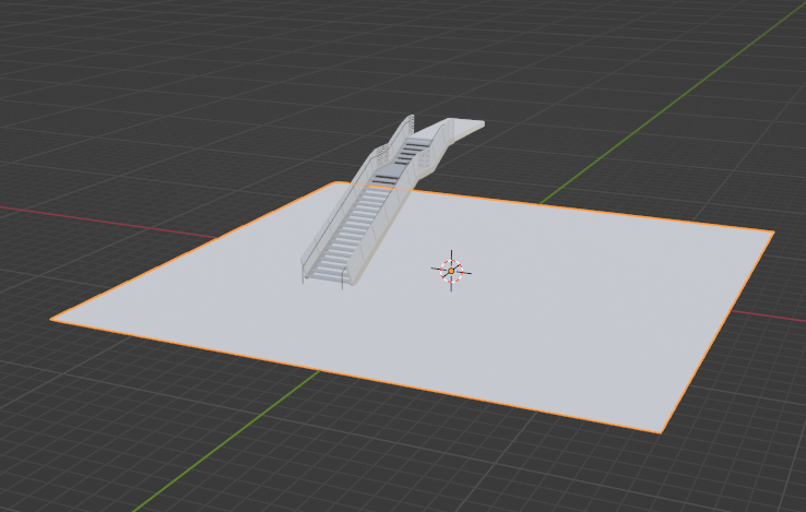
Land and stairs
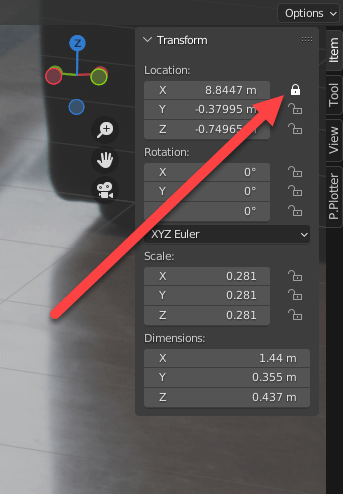
To conveniently check the size in meters, we can refer to Dimensions, which appears in the sidebar.
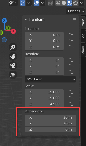
Show dimensions
Installing Columns and Walls
Just like the floor, we can erect columns and walls.
Here, the snapping function is used to ensure that the columns and walls are properly placed on the ground (we discuss the snapping function in detail below). When snapping, use either [x], [y] or [z], and limit the movement to one axis only. Otherwise we can cause problems like, for example, an object in the foreground may snap to an object in the background, causing the shape of the object to be distorted.
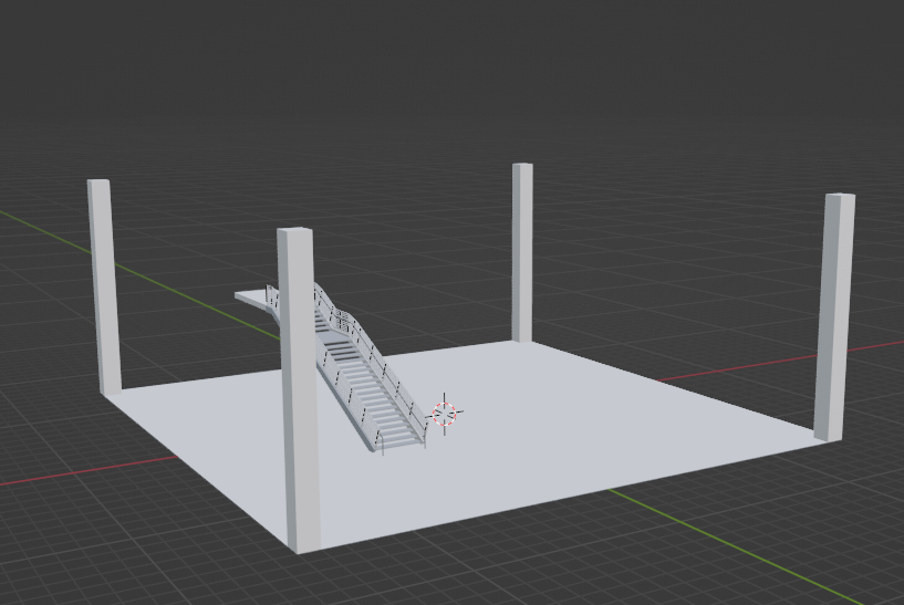
Installing columns
If you already have a floor plan, it will be easier to visualize the building if you install walls and other objects at the same time based on the floor plan. There is no specific order for this, but you can proceed by placing walls and other necessary objects while visualizing the building.
Using Collections
When placing walls and floors, we often work in wireframe mode to correctly match them, but it can be difficult to see what is going on, especially in a high-rise building where the layout is different on each floor. Furthermore, when modeling a lower floor after modeling a higher floor, it may be difficult to see the lower floors as they are obscured by the higher floor. For this reason, objects on each floor should be grouped together in separate collections to make it easier to switch views.
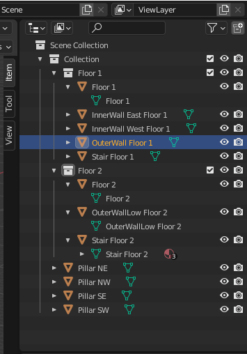
Collection display
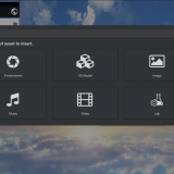
Using the Asset Browser
Frequently used objects can be conveniently accessed by registering them in the asset browser as they are placed.

Asset browser
For more information, please refer to the dedicated article on asset browsers.
![[Blender] How to Super-Efficiently Create Scenes with the New Asset Browser](https://styly.cc/wp-content/uploads/2022/02/asset-browser-eyecatch-160x160.png)
Setting Translucent Objects
To model translucent objects such as windows, change the “Blend Mode” to “Alpha Blend” for transparent areas and lower the “Alpha” of the material.
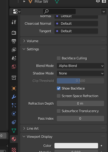
Blend mode
Modifiers such as the “Array” modifier can be used to easily model buildings with a series of windows, such as office buildings.
For more information on modifiers, please refer to the following article.
![[Introduction to Blender] Using modifier tools (1) Introduction – Generate(Array/Bevel/Boolean)](https://styly.cc/wp-content/uploads/2021/06/eye-160x160.png)
Architectural Examples
Here we provide an example of a complete assembly.
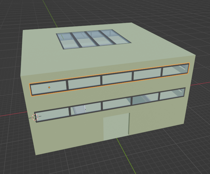
Assembled Building
Useful Features in VR Architecture
Next we will introduce two functions that are useful for VR architecture.
In VR architecture, objects are placed and assembled, and there are many situations where it is necessary to place and align objects precisely. Two functions that make this easy are the “Snap To” function and the “Set Origin” function.
Snapping
Blender allows you to set snapping when moving objects. The settings are as follows:
| Increment | Distance between snapping points on the grid. |
| Vertex | Snap to the most recent vertex. |
| Edge | Snap to the nearest edge. |
| Face | Snap to the immediate surface. |
| Volume | Snap to the most recent volume. |
| Edge Center | Snap to the midpoint of the nearest edge. |
| Edge Perpendicular | Snap at right angles to the nearest edge. |
The U magnet button next to the menu specifies whether the snap function is always enabled. If this is not specified, it will only be enabled while the [Ctrl] key is pressed.
Behavior when snapping is enabled
Snapping allows us to place objects well, as described above, and is useful in the following two cases:
- When you want to place an object on top of another object, such as placing a column on the floor.
- When you want to place or align an object precisely, such as placing a wall at the edge of a floor.
Set the Origin
Blender’s origin is usually set to the center of the object, such as a cube or other primitive. The origin is displayed as a circular point.
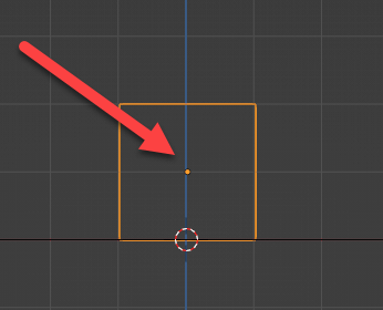
Indication of Origin
Normally, this is not a problem, but there will be cases where you want to set the origin in another position. There are two common such cases:
- While editing an object, the shape of the object has changed a lot and the origin has become a great distance away from the object.
- When placing a ceiling or floor, you want to place it at an exact height.
In the latter case, for example, if I want to place a ceiling at a height of 4 meters and the origin is specified at the center of the thickness of the ceiling (and the upstairs floor), it will be difficult to accurately place the ceiling at a height of 4 meters. In this case, the origin can be aligned to the desired edge to ensure accurate placement.
To change the origin, use the “Set Origin” menu.
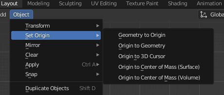
Set Origin Menu
The two main functions used in this menu are “Origin to Geometry” and “Origin to 3D Cursor”.
Move Origin to Geometry
This option moves the origin to the center of the currently selected geometry.
Setting the origin to an object
This tool is especially useful if the origin position deviates significantly outside of an object. You can use this to return and keep the origin within the object.
Move Origin to 3D Cursor
This option moves the origin to the position of the 3D cursor.

Moving the origin to the 3D cursor.
In the above example, the origin is moved to the bottom of the object. The steps are as follows
- Enter the edit mode of the target object and specify the area to be covered (in this case, the bottom part).
- Press [Shift]-[S] to bring up the “Snap” menu, then press “(Cursor to Selected)” (or [2] key).
- Return to the object mode and select the target object.
- Select “Origin to 3D Cursor” from the Origin Settings menu.
Caution
Estimate the Scale in the Early Stages of Building
After the walls, ceilings, and such are built up, problems may be discovered, such as ceilings that are too low.
While it is easy to correct these problems in the early stages of modeling, it is quite troublesome to correct them after a high-rise building has been built, so it is important to build at the correct scale from the beginning.
It is useful to occasionally check whether the scale is set correctly by using an avatar model or a model for scale confirmation.
Pay Special Attention to Stairs
A surprising pattern when building a staircase is that the ceiling can be too low, causing users to hit their head. Even if there is enough clearance to avoid hitting your head, if the ceiling is too low it will create a feeling of oppression, so make sure there is as much room as possible.
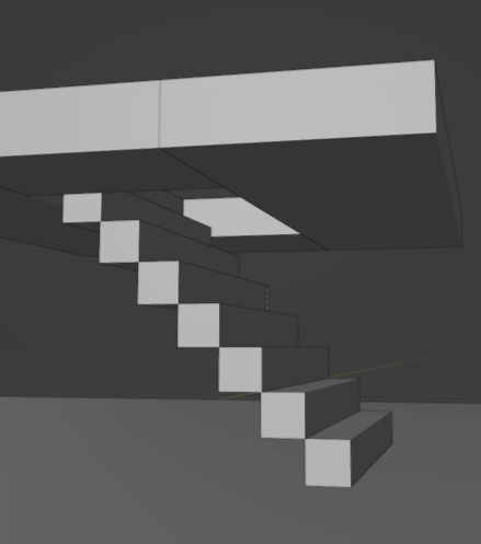
Example of a bad staircase
The above example is exaggerated, but this is the kind of design you may unintentionally create when you are trying to build a short staircase or steps in an environment with low ceilings.
Unless the staircase is very long, the ceiling area directly above the staircase (or in the case of an extremely short staircase, plus the stairwell is more than the length of the staircase) should be vaulted.
As a side note, there does not seem to be any statutory specification for the height of the ceiling above the stair in actual buildings, and this design error is often experienced by students of architecture. If you are interested, please refer to architectural websites and books, as well as building codes and other laws and regulations, for more realistic modeling.
Note the Location of the Origin
Although there is usually no problem when uploading STYLY under normal conditions, if the origin is misaligned when combining with other models or passing on to others, it may cause inconvenience. Since a misaligned origin can cause misidentification even during normal or modeling operations, the origin should be kept within the model unless there is a particular reason for it to be misaligned.
Regarding Steps
Since it depends on the VR environment whether steps can be crossed or not, collider settings are required for each environment.
Please refer to the dedicated article on collider settings.
When uploading VR buildings to STYLY, the collider needs to be specified for all objects in places where teleportation is specified or for objects that you want to avoid passing through, so you need to upload buildings using Unity prefab.
Application: Photo-Matching of Assets using Perspective Plotter
The “Perspective Plotter” allows modeling based on perspectives from photographs using a method called photo-matching. Photo-matching can be used for modeling based on perspectives even when images from all directions, such as three-view plans, are not available.
To illustrate this method, we will use the staircase of the Research Support Buidling from NASA’s image archive, which is available in the public domain.
Please note the following points when selecting photos to be used.
If the photo has been edited in post-processing, it may not be possible to match the perspective.
Sketches must be accurately drawn, such as blueprints, otherwise it will be difficult to match their perspective.
Photos with special lenses such as fisheye lenses cannot be aligned.
This add-on is available on Blender Market and Gumroad for $15.
First, purchase Perspective Plotter and install it.
Please refer to the following article for the process of purchasing and installing the add-on from Blender Market.

The add-on is installed as a sidebar and appears in the sidebar by selecting the camera display mode (numeric keypad [0] key or “(View)” -> “(Camera)” -> “(Active Camera)”).
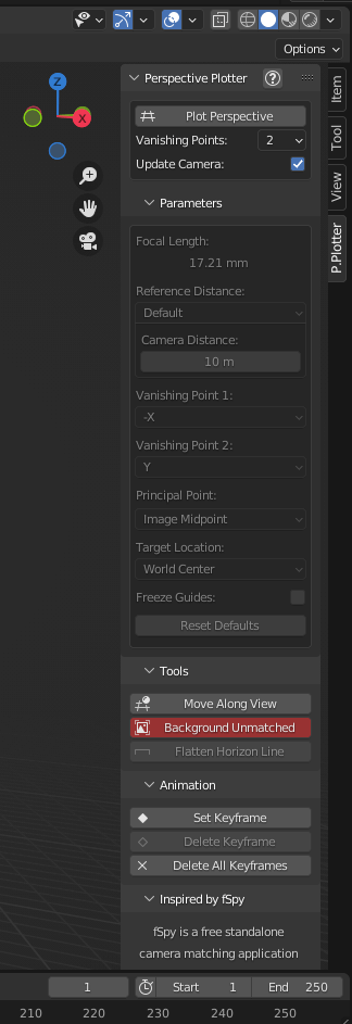
Perspective Plotter sidebar
Before using perspective plotter, we need to make some preparations.
With the camera active, check “Background” under “Object Properties”.
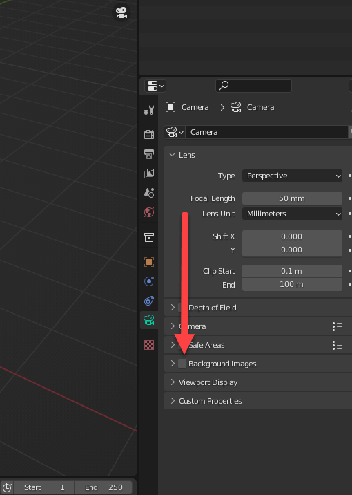
Select Background Image
Check this, open the dropdown menu (“>”), use the “Add Image” button, and select a background image.
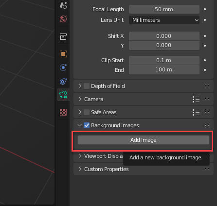
Select Background Image
When a background image is added, the image is displayed in the view as a background image, as shown here.
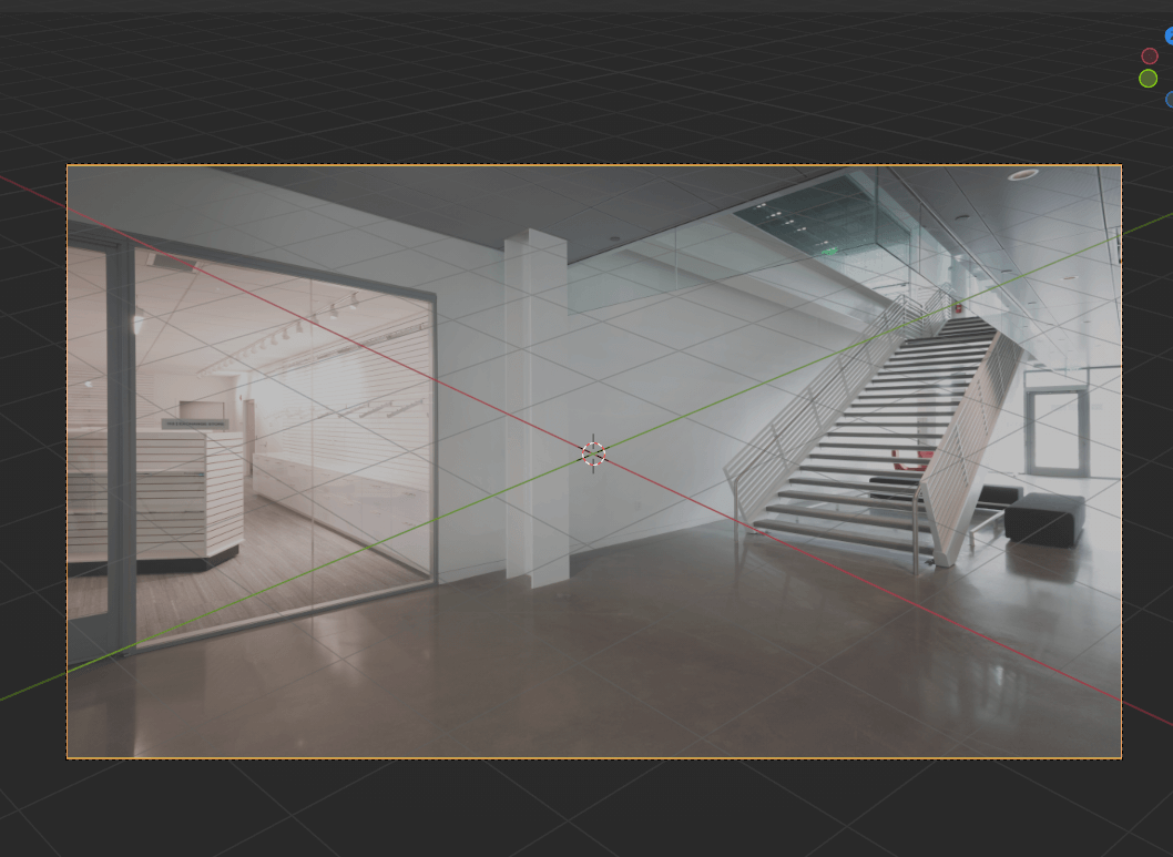
View after adding as background
In this state, press the Plot Perspective button at the top of the Perspective Plotter menu.
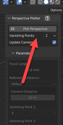
Plot Perspective button
When the button is pressed, this button will be replaced by “Plotting…” and the view will show green and blue bars and a white circle.
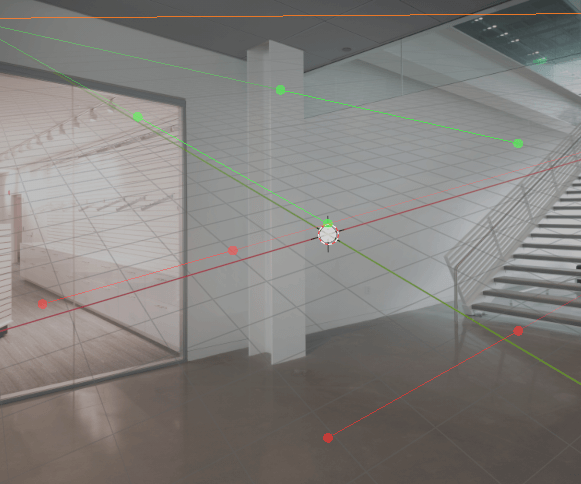
Displayed bars and circles
By using this interface, you can change the parameters of the camera to obtain an angle which correctly matches the scene.
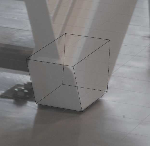
Let’s put a surface to the test.
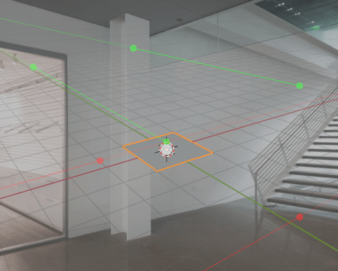
Placing a surface
The center point can be changed with the white circle.

Movement of center point
We can see that the angles, etc. do not fit together. This is because the angle the camera is looking at is different from the angle of the background image. By moving the green and red bars, we can determine the vanishing point and see what it is like to be present, which will facilitate modeling.
If you have studied painting, you are probably familiar with perspective. The main function of this add-on is to determine the vanishing point and set the angle of view correctly so that the image fits in the view.
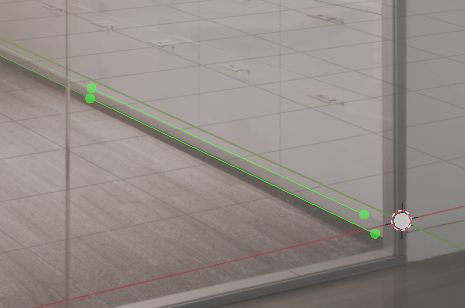
You should place the green and red bars along straight lines in the photo. The lines of the same color should then be parallel in the actual environment.
Edit Perspective
Try to place these lines as carefully as possible. It is important at this stage to place each color pair of lines as far apart as possible.
For example, the following designations are too close together and are not good.
Example of line designation too close together.
If the configuration is unresolved, for example, if the specification is impossible, the display will turn red and show “Invalid Configuration”. If this message appears, adjust the angle and placement of the lines.
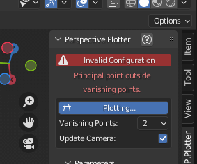
Unresolved state
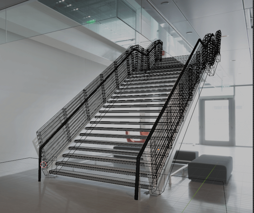
Now, we will model from this view. As shown below, we will create the object based on the apparent appearance of the subject. The modeling is conveniently done with wireframes.
Object Placement
For example, a model of a railing would look like this.
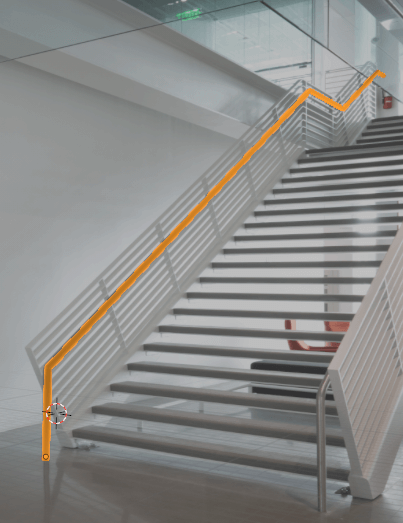
Handrail model
Things to Note when Modeling with Perspective Plotter
There are several important points to consider when modeling, which are explained below.
Edit with Limited Axis Movement
When modeling, each part must be placed in the correct position, just as in normal modeling. If the model is based on a camera view, any apparent and unnecessary movement or rotation will destroy this assumption, causing the actual object placement to be incorrect, even though it is correct in the camera view. For this reason, it is a best practice to use the lock function to prevent the user from moving unused axes during editing.
Shaft Fixation
Also, be sure to use the [x], [y], and [z] keys in a timely manner when moving, rotating, and performing other operations, and to limit operations to a single axis.
Check Other Views
In addition to the camera view, it is important to check the views from the side, from the top, and from the side in a timely manner.
When editing, it is also important to start with an easy-to-understand view first, and then return to the camera view for fine-tuning to ensure modeling consistency.
Do Not Insist on Matching it Perfectly
In some cases, photo-matching is not compatible with the consistency of the model data and its appearance from the camera due to matching discrepancies and lens distortion.
In such cases, priority should be given to the consistency of the placement in the finished 3D view, without being overly concerned about the consistency with the camera.
In addition, for areas that are hidden from the camera, this should be done either by placing and matching other camera views that show them, or by modeling them from one’s imagination.
Model Created
Each part was modeled, and the final model is shown below.
Model created
As mentioned above, some compromises were made when adjusting to the camera view in some locations.
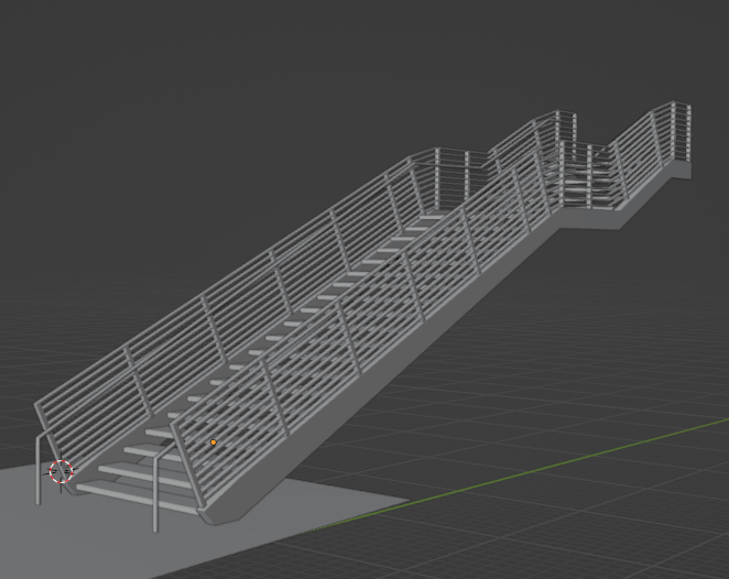
Completed model
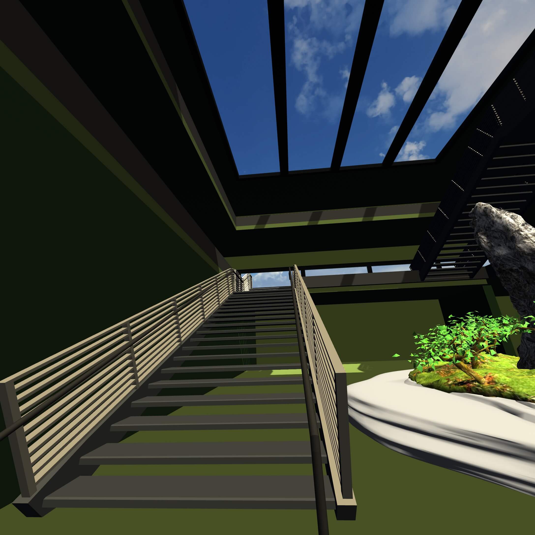
Import into STYLY
The completed model was imported into STYLY and the scene is shown below.
We first output the model to FBX, then import it into Unity, and then set the collider.
See the following article for details on how to do this.
![[Unity Tutorial] Learning About Colliders](https://styly.cc/wp-content/uploads/2019/07/スクリーンショット-2019-07-08-14.30.36-160x160.png)
For buildings, one will mostly be using the Box Collider or Mesh Collider as needed. When viewed in VR, you get the feeling that you are standing inside the building.
A video of me viewing a building in VR
How to Create a Texture Based on a Photo
Use the following method to create a texture based on an imported image. The following example uses a photo of the MSFC BUILDING, a NASA public domain image.
First, specify the vanishing point.

Photo-matched building
Execute “Project from View” in the UV menu.
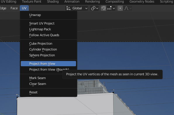
Projection from view
Specify the draft image (the image used for photo matching) as the model’s material.
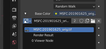
Designate a rough sketch as a material
Textures are then projected onto the model.
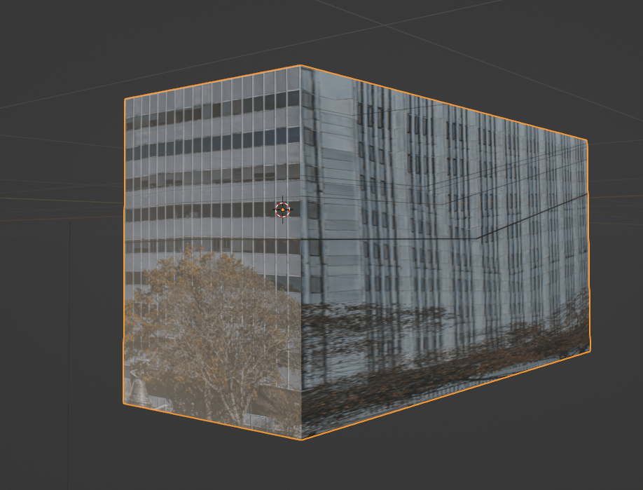
Projected results
As our results show, there are several problems when textures are applied in this way.
- The texture will inevitably be distorted.
- Textures cannot be applied to areas that are not visible.
Therefore, it can difficult to import a good texture from a photo, depending on the quality of the image used for the texture. However, it may be possible to use it for background models, or other less important textures, so try it if necessary.
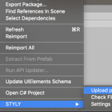
How to upload to STYLY
Upload your 3D model to STYLY.
Create a STYLY account
How to create an account.
How to upload to STYLY.
How to upload from Unity to STYLY
For questions about STYLY, bug reports, and requests for improvements, please contact the STYLY FORUM
https://jp.forum.styly.cc/support/discussions
STYLY provides many types of objects and skyboxes, which can be used to place furniture and decorations. Also, by using PlayMaker or modifiers, it is possible to add features such as automatically turning on the lights when you pass through the building. There are also several add-ons that specialize in the creation of buildings and structures, which can be used to further expand the scope of your work.
The following is an example of a creation using the ArchMesh add-on.
![[Blender 2.8] Using Archimesh as an Add-on for Architecture (1), “Let’s make a base room.”](https://styly.cc/wp-content/uploads/2020/06/Head-160x160.png)
We hope you enjoy designing your own VR architecture and buildings.